



What Steel Impact Toughness Means—and What Charpy Energy Does Not Mean
Impact toughness versus strength, ductility, and fracture toughness
Impact toughness is a material’s resistance to fracture when a load is applied rapidly, often through a notch that concentrates stress. It is not the same property as strength, tensile ductility, or fracture toughness, although all can affect the result.
Related mechanical properties
- Yield strength
- The stress at which plastic deformation begins during a tensile test.
- Tensile strength
- The maximum engineering stress reached during a tensile test.
- Ductility
- Plastic deformation before fracture, commonly expressed through elongation or reduction of area.
- Fracture toughness
- Resistance of a pre-existing crack to extension under defined specimen, thickness, loading, and validity conditions.
Yield strength describes the stress at which plastic deformation begins during a tensile test. Tensile strength is the maximum engineering stress reached in that test. Neither value states how a steel containing a sharp crack will behave during a fast loading event. A high-strength steel can have poor resistance to cleavage fracture, particularly at low temperature, while a lower-strength steel can absorb substantial impact energy.
Ductility describes plastic deformation before fracture, commonly through elongation or reduction of area in a tensile specimen. Impact toughness includes a rate effect and a notch effect that ordinary tensile ductility does not reproduce. A notched Charpy specimen has little opportunity to redistribute stress through uniform deformation. The notch therefore makes local constraint and crack initiation central to the test.
Charpy absorbed energy is not a KIC value or a complete fracture-toughness measurement. Strong evidence
Fracture toughness A crack-resistance property measured under defined specimen geometry, loading, thickness, crack, and validity conditions.
Fracture toughness is a different class of property. Values such as , , or the crack-tip opening displacement (CTOD) describe the resistance of a pre-existing crack to extension under defined specimen, thickness, loading, and validity conditions. , for example, is a plane-strain fracture-toughness value obtained under conditions intended to suppress specimen-size and plasticity effects. A Charpy V-notch is sharp enough to promote fracture initiation, but it is not a fatigue-precracked fracture-toughness specimen, and its absorbed energy is not a value.
Crack-arrest behavior must also remain separate. A material may resist initiating a crack yet provide different resistance to a running crack. For pipeline steels, the drop-weight tear test examines crack-arrest behavior by measuring ductile-shear and cleavage fractions on fracture surfaces over a range of impact temperatures. That method is not interchangeable with Charpy testing.
Why absorbed energy is an indirect material indicator
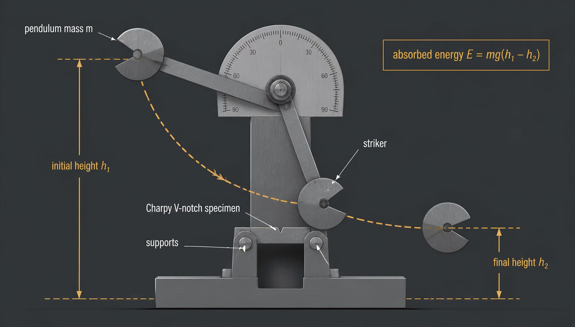
In a conventional Charpy test, a pendulum strikes a notched, simply supported specimen. The difference between the pendulum’s initial and final energy indicates the work absorbed by the specimen and, in practice, by some associated losses accounted for by the test procedure. The result is reported as absorbed impact energy, usually in joules. NIST described Charpy testing in 2024 as a high-loading-rate test that measures energy absorbed during fracture and provides an indirect measure of impact toughness.
[1] ISO 148-1:2016 Metallic materials — Charpy pendulum impact test — Part 1: Test method. International Organization for Standardization. ISO standard, 2016.
“Indirect” is the important word. The measured energy combines several events: plastic deformation near the notch, crack initiation, stable or unstable crack growth, friction and machine effects, and the final fracture process. It is not a single material constant that can be transferred unchanged to every component geometry or loading rate. ASTM E23 covers Charpy simple-beam and Izod cantilever-beam impact tests, including specimen requirements, procedures, machine verification, reporting, and determination of shear-fracture appearance. ISO 148-1:2016 specifies Charpy V-notch and U-notch pendulum impact testing for metallic materials. The notch type matters; V-notch and U-notch results should not be treated as equivalent without a specified basis.
Fracture appearance supplies evidence that the energy number alone cannot provide. Ductile tearing generally requires substantial plastic deformation and absorbs more energy. Cleavage-dominated fracture usually absorbs less. The percentage of shear fracture, lateral expansion, and the position of a result on a ductile-to-brittle transition curve can therefore change the engineering interpretation of the same nominal energy.
Instrumented testing can add information about the force-time or force-displacement response. ISO 14556:2023 specifies instrumented Charpy V-notch testing and the equipment used to measure and record additional fracture behavior; ISO 148-1:2016 does not cover that instrumented method. Machine condition also matters. ASTM E23 and ISO 148-2 provide verification requirements, and NIST’s Charpy Machine Verification Program uses certified specimens for periodic machine checks.
The danger of treating one Charpy value as a universal property
A statement such as “this steel has 80 J Charpy toughness” is incomplete. The temperature may be absent. So may the notch geometry, specimen orientation, plate thickness, heat-treatment condition, sampling location, test direction, number of specimens, governing standard, and fracture appearance. Each omission can alter the meaning of the result.
Ferritic steels commonly show a ductile-to-brittle transition as temperature falls. A room-temperature result can therefore provide little assurance about behavior at a colder service temperature. Even within the transition region, small temperature changes can produce large shifts in energy and fracture mode. Upper-shelf energy, transition-region energy, and lower-shelf behavior arise from different fracture mechanisms, so separate correlations are required when Charpy data are used to estimate a lower-bound fracture-toughness value. Such correlations can support engineering screening for defined ferritic-steel conditions; they do not turn absorbed energy into plane-strain fracture toughness.
A Charpy result cannot be interpreted independently of its sampling plan and specimen orientation. Strong evidence
[2] ASTM A673/A673M: Standard Specification for Sampling Procedure for Impact Testing of Structural Steel. ASTM International. ASTM International standard, 2025.Specimen orientation is another decisive variable. A longitudinal Charpy specimen samples the steel differently from a transverse or through-thickness specimen because rolling direction, inclusions, banding, and grain structure affect crack growth. ASTM A673/A673M specifies sampling procedures for longitudinal Charpy V-notch testing of structural steel and distinguishes heat-testing from piece-testing frequencies. Sampling is therefore part of the result, not an administrative detail added after the test.
NIST’s 2011 assessment of side-grooved Charpy specimens found that side grooves reduce accumulated plastic deformation at upper-shelf energies and promote splitting, with splitting severity greatest near the ductile-to-brittle transition temperature. That finding illustrates why specimen geometry can change both the measured energy and the fracture surface.
A Charpy result is useful when reported as a defined test observation: material condition, standard, notch, orientation, temperature, sampling plan, energy, and fracture appearance together. Without that context, one number is not a universal property of the steel and cannot by itself establish service fracture safety.
The Charpy Pendulum Test: Specimen, Notch, and Fracture Event
Standard Charpy V-notch and U-notch specimens
A Charpy test uses a small, rectangular bar with a machined notch in one face. The specimen is placed horizontally across two supports, then struck by a pendulum on the face opposite the notch. This arrangement forces the crack to initiate at a controlled location and propagate through the remaining ligament. The result is not simply a property of “the steel”; it is a response from a particular specimen, notch, orientation, temperature, and material condition.
ISO 148-1:2016 specifies Charpy V-notch and U-notch pendulum impact testing for metallic materials. The V-notch and U-notch designations describe the notch profile, not two interchangeable test results. A V-notch has inclined sides meeting at a controlled root radius, producing a relatively acute stress concentration. A U-notch has a rounded root and therefore a different local stress field. Notch depth, included angle, root radius, specimen dimensions, and surface finish are prescribed by the applicable standard. Small departures can alter crack initiation and plastic deformation before fracture.
The commonly used full-size Charpy specimen is nominally 10 mm × 10 mm × 55 mm, although the applicable standard and product specification govern the permitted dimensions and reduced-size alternatives. For a V-notch specimen, the notch is normally 2 mm deep with a 45-degree included angle and a specified root radius. Those figures describe a standardized geometry, not a general recipe for any impact specimen. U-notch dimensions likewise follow the selected standard and must not be inferred from V-notch practice.
| Method | Specimen support | Primary result or scope |
|---|---|---|
| Charpy | Simply supported beam | Pendulum impact energy and, where required, shear-fracture appearance |
| Izod | Cantilever beam | Pendulum impact test under the applicable ASTM E23 requirements |
ASTM E23 covers both Charpy simple-beam and Izod cantilever-beam impact tests. That distinction matters. An Izod specimen is held as a cantilever and struck above the support, whereas a Charpy specimen is supported at both ends. A value from one method cannot be relabeled as the other. ASTM E23 also addresses specimen requirements, procedures, machine verification, reporting, and determination of shear-fracture appearance.
The notch is usually oriented so that the striker loads the unnotched face and the notch lies on the tensile side of the bending section. Crack initiation then occurs at the notch root as the ligament bends. Specimen orientation must also be reported. In rolled plate, for example, a longitudinal Charpy V-notch specimen samples a different combination of rolling direction, inclusions, banding, and grain structure than a transverse or through-thickness specimen. ASTM A673/A673M specifies sampling procedures for longitudinal Charpy V-notch testing of structural steel and distinguishes heat-testing from piece-testing frequencies. Sampling is therefore part of what the reported result means.

Pendulum impact and absorbed-energy calculation
Pendulum impact sequence
- Raise The pendulum is raised to a defined height and given a known potential energy.
- Release The pendulum swings downward at a controlled velocity.
- Strike The striker impacts the specimen on the face opposite the notch.
- Fracture The specimen fractures or bends across the remaining ligament.
- Measure The difference between the initial and final pendulum energy is used to report absorbed energy.
Before release, the pendulum is raised to a defined height and given a known potential energy. It swings downward, strikes the specimen at a controlled velocity, fractures or bends the bar, and rises on the opposite side to a lower height. In simplified form, the absorbed energy is
where is the effective pendulum mass, is gravitational acceleration, and and are the initial and final pendulum heights. Actual machines account for mechanical losses, friction, windage, striker geometry, and machine calibration. The displayed value is conventionally reported in joules.[3] Charpy Machine Verification Program. National Institute of Standards and Technology. NIST program resource, 2024.
NIST describes Charpy testing as a high-loading-rate test that measures energy absorbed during fracture and provides an indirect measure of impact toughness. Machines are periodically checked through procedures such as the NIST Charpy Machine Verification Program, with certified specimens used under ASTM E23 and ISO 148-2. Verification establishes that the machine produces acceptable results; it does not remove variation caused by steel chemistry, heat treatment, specimen preparation, or sampling.
The energy includes more than the energy required to create new crack surface. It also includes elastic and plastic bending, crack initiation, stable tearing, frictional effects, and other deformation occurring during the event. A high value often accompanies ductile tearing, while a low value commonly accompanies cleavage-dominated fracture, but energy alone does not identify the complete fracture process. The broken surface should be examined and shear-fracture appearance recorded where required.
Temperature can change the result sharply. Ferritic steels such as many grades of carbon and low-alloy structural steel may show a ductile-to-brittle transition as temperature falls. One room-temperature value cannot represent behavior at a winter design temperature, a weld heat-affected zone, or a rapid crack event in service. Charpy energy can support specified correlations for estimating lower-bound fracture toughness in ferritic steels, but separate relationships apply to lower-shelf, transition-region, and upper-shelf behavior. It is not a plane-strain fracture-toughness value, nor does it directly establish crack-arrest performance. The drop-weight tear test is a separate method for pipeline-steel crack-arrest behavior, measuring ductile-shear and cleavage fractions across impact temperatures.
Simple-beam geometry, support conditions, and notch orientation
The Charpy specimen behaves approximately as a simply supported beam during impact. Its ends rest on anvils at a prescribed span, while the striker applies a concentrated load near the midpoint. The supports, span, striker radius, clearance, alignment, and impact velocity influence the bending stress and the amount of constraint around the notch. A specimen that is poorly seated, misaligned, damaged, or struck away from the specified location may produce a misleading value even when its dimensions appear correct.
Notch orientation controls which material direction is placed across the crack path. Rolling texture, elongated inclusions, weld solidification structure, segregation, and prior deformation can make longitudinal, transverse, and through-thickness results differ substantially. Machining marks, excessive root radius, burrs, corrosion, and heat generated during preparation can also change crack initiation. Comparability requires the same standard, notch type, dimensions, orientation, temperature, support arrangement, and preparation history.
Side grooves illustrate how geometry can change fracture behavior further. NIST reported in 2011 that side grooves reduce plastic-deformation accumulation at upper-shelf energies and promote splitting; splitting severity is greatest near the ductile-to-brittle transition temperature. Such specimens may be useful for a defined investigation, but their results should not be merged with ordinary Charpy values without a stated method.[4] ISO 14556:2023 Metallic materials — Charpy V-notch pendulum impact test — Instrumented test method. International Organization for Standardization. ISO standard, 2023.
ISO 14556:2023 specifies instrumented Charpy V-notch pendulum impact testing, which records force and displacement or related signals to provide additional information about fracture behavior. ISO 148-1:2016 does not substitute that instrumented method for the conventional energy test. The conventional Charpy result is a standardized response to one controlled impact event—not a direct simulation of every service crack, loading history, restraint condition, or crack-arrest problem.
ASTM E23, ISO 148-1:2016, and ISO 14556:2023
Charpy results are standardized measurements, but they are not automatically interchangeable across standards. A reported value depends on the specimen, notch, orientation, test temperature, pendulum machine, verification status, material condition, and reporting rules. It also describes absorbed impact energy—not plane-strain fracture toughness, crack-arrest resistance, or every aspect of fracture behavior.
NIST describes Charpy testing as a high-loading-rate test that measures the energy absorbed during fracture and provides an indirect measure of impact toughness (NIST, 2024). That distinction matters for ferritic steels, which commonly undergo a ductile-to-brittle transition as temperature falls. A room-temperature result can therefore conceal a sharp reduction in energy at a lower service temperature.
What ASTM E23 controls and reports[5] ASTM E23: Standard Test Methods for Notched Bar Impact Testing of Metallic Materials. ASTM International. ASTM International standard, 2025.
ASTM E23 covers both Charpy simple-beam impact tests and Izod cantilever-beam impact tests (ASTM International, 2025). For Charpy work, its requirements address specimen dimensions and notch details, specimen support and orientation, test procedure, machine operation, verification, and reporting. The standard also includes determination of shear-fracture appearance, allowing the fracture surface to supplement the absorbed-energy result.
That coverage makes the reported number more than a pendulum reading, but it does not turn the test into a direct fracture-toughness measurement. The machine records the energy difference associated with the broken specimen, commonly reported in joules or foot-pounds. The value is meaningful only alongside the notch type, specimen orientation, test temperature, material identification, and applicable acceptance requirement.
Machine condition is part of the measurement chain. Charpy machines are periodically verified with certified reference specimens under ASTM E23 and ISO 148-2 through programs such as NIST’s Charpy Machine Verification Program. A machine that has not passed the applicable verification requirements may produce a numerically precise result that is still unsuitable for comparison.
ASTM E23 also does not define the entire sampling meaning for every steel product. ASTM A673/A673M specifies sampling procedures for longitudinal Charpy V-notch testing of structural steel and distinguishes heat-testing from piece-testing frequencies. Two results obtained by the same impact procedure can thus represent different levels of production surveillance if their sampling plans differ.
Fracture appearance supplies evidence that energy alone cannot. Ductile shear generally absorbs more energy, whereas cleavage-dominated brittle fracture generally absorbs less. The percentage of shear fracture can identify where a specimen lies on a transition curve, although appearance measurements must follow the applicable reporting procedure. A high-energy upper-shelf result does not establish a particular value of , , or crack-arrest toughness.
Scope of ISO 148-1:2016 for conventional Charpy testing
ISO 148-1:2016 specifies Charpy V-notch and U-notch pendulum impact testing for metallic materials (ISO, 2016). It defines the conventional test arrangement: a notched specimen is supported as a simple beam and broken by a pendulum striker under specified conditions. The resulting absorbed energy is a method-defined impact value, not a universal material constant.
The V-notch and U-notch configurations are not interchangeable. Their notch geometry changes stress concentration, plastic deformation, crack initiation, and the energy needed to fracture the specimen. Specimen dimensions, notch form, orientation, temperature, striker details, and machine verification must therefore accompany any comparison between ISO 148-1:2016 results and results from another method.
ISO 148-1:2016 excludes instrumented Charpy testing. It is concerned with the conventional pendulum test and its absorbed-energy determination; measurements requiring force and displacement recording belong to ISO 14556. ISO 148-2 addresses verification of Charpy pendulum impact machines, so compliance with ISO 148-1:2016 should not be treated as proof that an unverified machine produces comparable data.[6] What fracture toughness can I assume for a ferritic steel if I know that it meets a certain Charpy energy requirement?. TWI. TWI Technical Knowledge, 2024.
The standard’s scope also does not erase material-specific effects. A ferritic steel may show a lower shelf, a transition region, and an upper shelf as temperature changes. Separate relationships are needed when Charpy energy is used to estimate a lower-bound fracture-toughness value in these regions; the relationships for lower-shelf, transition-region, and upper-shelf behavior are not the same (TWI, 2024). Such correlations apply only under their stated material, geometry, and temperature limits.[7] Side-Grooved Charpy Impact Testing: Assessment of Splitting and Fracture Properties of High-Strength Steels. National Institute of Standards and Technology. NIST publication, 2011.
NIST research published in 2011 on side-grooved Charpy specimens found that side grooves reduce accumulated plastic deformation at upper-shelf energies and promote splitting. Splitting severity was greatest near the ductile-to-brittle transition temperature. That finding illustrates why specimen preparation can alter fracture behavior without changing the nominal Charpy label.
Instrumented Charpy testing under ISO 14556:2023
ISO 14556:2023 specifies instrumented Charpy V-notch pendulum impact testing and the measurement and recording equipment used for it (ISO, 2023). In addition to the pendulum’s overall absorbed energy, the instrumented system records force-related data during impact, allowing analysis of stages such as crack initiation, unstable propagation, and subsequent fracture, subject to the standard’s measurement requirements and data interpretation.
This can provide information about fracture behavior rather than only one integrated energy value. Force-displacement or force-time records may help distinguish initiation energy from propagation energy and may reveal differences between ductile tearing, cleavage, and mixed fracture. The additional signals do not automatically produce a plane-strain fracture-toughness value; specimen size, constraint, notch acuity, calibration, and analysis assumptions remain important.
ISO 14556:2023 is specifically an instrumented Charpy V-notch method. Its results should not be merged casually with conventional ISO 148-1:2016 V-notch values or ASTM E23 values, even when specimens appear similar. Different equipment, calibration, definitions, filtering, reporting conventions, and acceptance criteria can change the reported quantities.
Nor should Charpy testing be confused with the drop-weight tear test. That separate method examines pipeline-steel crack-arrest behavior by measuring ductile-shear and cleavage fractions across impact temperatures. It answers a different engineering question. Charpy energy, instrumented impact data, fracture appearance, and crack-arrest measurements are related evidence, not interchangeable labels.
Machine Verification, Calibration, and the Credibility of a Result
Direct verification and certified reference specimens
A Charpy result is credible only when the complete test system has demonstrated that it can produce a known response. Machine verification provides that demonstration. It is not the same as checking whether the pendulum swings, whether the specimen fits between the anvils, or whether the scale displays a plausible number.
Under ASTM E23 and ISO 148-2, direct verification uses certified reference specimens with established impact-energy values. The laboratory breaks these specimens on the machine and compares the measured results with the certified range. Because the reference specimens have known behavior, they test the machine and its measurement chain under actual impact conditions rather than merely checking individual dimensions.
This distinction matters because Charpy testing is a high-loading-rate measurement. NIST describes the test as measuring the energy absorbed during fracture and providing an indirect measure of impact toughness. The pendulum must transfer energy through a short-duration fracture event, while the machine records the difference between its initial and final energy. Small mechanical losses or geometric errors can therefore affect the reported value.
A direct verification can expose several failure modes at once. Excessive pendulum friction reduces available energy before impact. A damaged, rounded, improperly oriented, or incorrectly dimensioned striker changes how the notch is loaded. Worn anvils or incorrect support spacing alter bending and contact conditions. Support misalignment can introduce torsion or uneven constraint. The machine may still produce a clean fracture and a believable dial reading while failing the reference-specimen requirement.
Machine capacity also has a defined role. A pendulum that is too large for the intended energy range may give poor resolution, while a machine with insufficient capacity cannot fracture the specimen correctly or may lose measurement accuracy near its limit. The applicable standard and machine design determine the permitted capacity, energy range, striker geometry, specimen supports, and indication system.
Verification is not simply a synonym for calibration. Calibration generally concerns the accuracy of a measuring element against a traceable reference. Verification asks whether the assembled Charpy machine, including its mechanical components and energy indication, produces acceptable results in the prescribed test. A laboratory may calibrate an encoder or inspect a scale and still have a machine that fails direct verification because the striker, bearings, friction, or supports are defective.
NIST's Charpy Machine Verification Program
NIST's Charpy Machine Verification Program supports periodic verification of Charpy machines using certified specimens in accordance with ASTM E23 and ISO 148-2. The program exists because machine-to-machine differences can be large enough to obscure material differences, particularly when measured energies are near a specification limit or when results are compared between laboratories.
The certified specimens are not substitutes for production specimens. They are control materials used to establish whether the machine's measured response falls within an accepted range. A passing result supports confidence in the test system at the time of verification; it does not certify every future test or prove that every specimen was correctly prepared, oriented, conditioned, and tested.
Routine checks remain necessary between formal verifications. Personnel should confirm striker and anvil dimensions, support alignment, pendulum position, machine level, friction losses, indication or instrumentation function, and the condition of guards and containment equipment. The specimen must meet the required dimensions, notch radius, notch depth, notch orientation, and surface condition. A notch inspection can identify burrs, excessive roughness, machining marks, or a radius outside tolerance. Those checks address specimen and machine geometry; direct verification addresses the measured fracture response of the assembled system.
Temperature control is a separate source of uncertainty. Ferritic steels can pass from ductile, high-energy fracture toward cleavage-dominated, low-energy fracture as temperature falls. A specimen tested at the wrong temperature may produce a perfectly repeatable number that answers the wrong question. The laboratory must control conditioning time, transfer time, bath or chamber temperature, and the temperature actually reached by the specimen. Operator procedure matters just as much: incorrect centering, a reversed specimen, delayed release, or a mistaken notch orientation can invalidate an otherwise passing machine.
ASTM E23 covers Charpy simple-beam and Izod cantilever-beam impact tests, including machine verification, reporting, and determination of shear-fracture appearance. ISO 148-1:2016 specifies Charpy V-notch and U-notch pendulum testing for metallic materials. Instrumented testing is separate: ISO 14556:2023 addresses instrumented Charpy V-notch testing and the equipment used to record additional fracture information.
Why a correct-looking impact value can still be unreliable
A numerical result can look reasonable and still lack material meaning. Verification cannot remove specimen-to-specimen scatter, heat-to-heat variation, orientation effects, or errors in sampling. ASTM A673/A673M specifies sampling procedures for longitudinal Charpy V-notch testing of structural steel and distinguishes heat-testing from piece-testing frequencies. The sampling plan is therefore part of what the result represents. Three properly tested specimens from an unrepresentative location do not characterize an entire structure.
Fracture appearance supplies evidence that the energy value alone cannot. Ductile shear generally consumes more energy than cleavage, but the same absorbed energy can arise from different combinations of shear, cleavage, splitting, and plastic deformation. NIST reported in 2011 that side grooves reduce plastic-deformation accumulation at upper-shelf energies and promote splitting, with splitting severity greatest near the ductile-to-brittle transition temperature. Specimen geometry can change the fracture process.
Nor is Charpy energy a plane-strain fracture-toughness value. Correlations may estimate lower-bound fracture toughness for specified ferritic steels and temperature regions, but separate relationships apply to lower-shelf, transition-region, and upper-shelf behavior. A room-temperature value cannot describe low-temperature service when the steel undergoes a ductile-to-brittle transition.[8] What is the drop-weight tear test?. TWI. TWI Technical Knowledge, 2024.
Finally, Charpy testing does not replace crack-arrest testing. The drop-weight tear test evaluates pipeline-steel crack-arrest behavior through ductile-shear and cleavage fractions over impact temperatures. It answers a different question. A verified machine makes a Charpy number more trustworthy as a measurement; it does not make that number a complete description of fracture resistance.
Temperature, Ferritic Steels, and the Ductile-to-Brittle Transition
Ferritic steels often show a ductile-to-brittle transition as temperature falls. At warmer temperatures, plastic deformation can develop around the notch and absorb substantial impact energy before the specimen separates. At colder temperatures, dislocation motion is more restricted, local stress rises rapidly at the notch root, and cleavage can spread with limited plastic deformation. The change is not represented by a single universal temperature or by one Charpy value.
A Charpy test records the energy absorbed by a notched specimen during fracture at a specified temperature and loading rate. NIST describes it as a high-loading-rate test and an indirect measure of impact toughness, not a direct plane-strain fracture-toughness test. The result also depends on notch form, specimen orientation, plate or product condition, test procedure, and sampling. ASTM E23 covers Charpy simple-beam and Izod cantilever-beam impact tests, while ISO 148-1:2016 specifies Charpy V-notch and U-notch pendulum testing for metallic materials. Those designations and procedures matter when results are compared.
Lower shelf, transition region, and upper shelf
| Regime | Typical fracture behavior | Interpretive caution |
|---|---|---|
| Lower shelf | Predominantly cleavage-like fracture with relatively low absorbed energy | Low energy does not by itself describe crack propagation in a structure |
| Transition region | Mixed cleavage and ductile shear with potentially large energy scatter | Small temperature changes can produce large changes in energy and fracture appearance |
| Upper shelf | Extensive plastic deformation and generally higher absorbed energy | Upper-shelf energy is not a direct fracture-toughness value |
Lower shelf The cold-temperature region of a ferritic-steel Charpy curve where absorbed energies are relatively low and fracture is commonly cleavage-dominated.
The familiar Charpy temperature curve is usually divided into three interpretive regimes. The lower shelf is the cold-temperature region in which absorbed energies remain relatively low and changes with temperature may be modest. Fracture is predominantly cleavage-like, although small ductile areas or shear lips can still appear. A low lower-shelf value signals limited plastic energy absorption; it does not by itself provide a complete description of crack propagation in a structure.
The transition region lies between the lower and upper shelves. Here, a modest temperature change can produce a large change in absorbed energy and fracture appearance. Some specimens may show mixed cleavage and ductile shear, and scatter can be substantial. The temperature associated with a specified energy, such as a contract requirement, is therefore not automatically the material's physical transition temperature. Another definition may use a midpoint energy, a fracture-appearance criterion, or a specified percentage of shear fracture.
On the upper shelf, the specimen absorbs much more energy through extensive plastic deformation before final separation. The measured value is still not a direct fracture-toughness value. Upper-shelf Charpy energy is affected by specimen dimensions, notch acuity, strain rate, orientation, and constraint. NIST reported in 2011 that side grooves in Charpy specimens reduce the accumulation of plastic deformation at upper-shelf energies and promote splitting, with splitting severity greatest near the ductile-to-brittle transition temperature. A side-grooved result should not be treated as interchangeable with an unmodified standard specimen.
These regimes are not points on a straight scale from “bad” to “good.” Separate relationships are used when Charpy energy is correlated with lower-bound fracture toughness for lower-shelf, transition-region, and upper-shelf behavior, as noted by TWI in 2024. Such correlations require an applicable steel class, temperature range, specimen configuration, and constraint assumptions. Charpy energy remains impact energy, measured in joules; fracture toughness is commonly expressed through parameters such as , , or a related crack-tip measure.
Cleavage fracture versus ductile shear
Cleavage is a rapid, brittle fracture process in which a crack advances along preferred crystallographic planes with little preceding plastic deformation. Its fracture surface often appears relatively bright and granular. Because only limited plastic work is done, cleavage-dominated specimens generally absorb less Charpy energy. The lower shelf is therefore associated with low energy and a high proportion of brittle fracture, though the exact appearance depends on steel, orientation, notch, and test temperature.
Ductile fracture develops through plastic flow and the nucleation, growth, and joining of microscopic voids. It usually consumes more energy and produces a fibrous or dull-looking surface, often with shear lips near the outer faces. The transition region can contain both mechanisms in one fracture surface. Reporting absorbed energy without fracture appearance can hide that change.
For this reason, standards and specifications may require the percentage of shear fracture as well as energy. A specimen with moderate energy and a mixed fracture is telling a different story from one with the same energy but predominantly ductile shear. ASTM E23 includes determination of shear-fracture appearance and reporting requirements. Instrumented testing can add force, displacement, and absorbed-energy information during the event: ISO 14556:2023 addresses instrumented Charpy V-notch testing, whereas ISO 148-1:2016 does not cover that instrumented method.
The drop-weight tear test provides another useful distinction. It is a separate pipeline-steel method for crack-arrest behavior, assessing ductile-shear and cleavage fractions across impact temperatures. Its results must not be substituted for Charpy energy or presented as the same measurement.
Why service temperature must govern test temperature
The governing test temperature should represent the lowest relevant service condition, with allowances required by the applicable design code and specification. A room-temperature Charpy result establishes performance only at, or near, that tested condition. It cannot establish lower-shelf position, transition behavior, or fracture appearance at a colder design temperature.
This limitation is especially important for ferritic structural steels. ASTM A673/A673M specifies sampling procedures for longitudinal Charpy V-notch testing of structural steel and distinguishes heat-testing from piece-testing frequencies. Sampling is part of the result's meaning: one compliant specimen set does not necessarily describe every location, orientation, heat, thickness, or product condition.
Test temperature should therefore be stated with the absorbed energy, specimen orientation, notch designation, standard, and any shear-fracture requirement. Machine condition matters too; ASTM E23 and ISO 148-2 provide verification frameworks, and NIST's Charpy Machine Verification Program uses certified specimens for periodic machine verification. Without those details, a reported “Charpy toughness” number is incomplete. Temperature is not a footnote to the result; for ferritic steel, it can determine whether the observed fracture is largely ductile or cleavage-dominated.
Sampling, Orientation, and Steel Processing History
ASTM A673/A673M and structural-steel sampling
A Charpy result describes a defined specimen taken from a defined piece of steel. For structural plate, ASTM A673/A673M is important because it specifies sampling procedures for longitudinal Charpy V-notch testing, rather than treating sampling as an administrative detail added after the test. The standard addresses where specimens are taken and how often impact samples are required under heat-testing or piece-testing provisions. Those choices form part of the result’s meaning.
The sampling location can matter because a plate is not perfectly uniform through its length, width, or thickness. Chemical segregation may be stronger near particular regions of an ingot or continuously cast product, while rolling reduction, cooling rate, and surface-to-center temperature differences can produce different microstructures through the thickness. A specimen cut from one permitted location therefore demonstrates the behavior of that sampled material under the specified plan. It does not automatically establish the behavior of every location in the plate, every plate from a production run, or every component fabricated from it.
ASTM A673/A673M should also be read with the applicable material specification and purchase or fabrication requirements. The edition and product rules determine the exact sampling provisions. A report that states only “Charpy tested” omits essential information: the governing standard, specimen orientation, test temperature, sample location, required frequency, absorbed-energy result, and any fracture-appearance requirement. ASTM E23 provides the general framework for Charpy simple-beam testing, including specimen requirements, procedures, machine verification, reporting, and determination of shear-fracture appearance. NIST’s Charpy Machine Verification Program describes the test as a high-loading-rate measurement of energy absorbed during fracture; it does not turn that energy into a direct plane-strain fracture-toughness value.
Longitudinal versus transverse testing
“Longitudinal Charpy” identifies the specimen orientation relative to the product’s principal rolling direction. In a longitudinal specimen, the specimen length is generally aligned with the rolling direction, while the notch orientation determines which direction the crack advances through the material. A transverse specimen is cut with its length across the rolling direction. These are different material directions, not interchangeable labels.
Rolling elongates grains and inclusions and can produce a banded microstructure. Consequently, a crack advancing across elongated features may encounter a different sequence of ferrite, pearlite, segregation bands, or inclusions than a crack advancing along them. The measured energy can change with orientation, especially in plate steels with strong texture, pronounced banding, or through-thickness weakness. The effect is not fixed by the grade name alone. Plate thickness, reduction ratio, reheating practice, controlled rolling, normalizing, quenching and tempering, and cooling history all contribute.
The notch and crack-propagation direction deserve equal attention. A longitudinal designation in ASTM A673/A673M is not a universal substitute for a transverse, through-thickness, or weld-related toughness requirement. If a structure will load a plate in a direction not represented by the test coupon, the reported value may be an incomplete basis for assessment. The engineer must match the specimen orientation to the anticipated crack path and to the requirement in the applicable design or material standard.
Temperature adds another limitation. Ferritic steels commonly undergo a ductile-to-brittle transition as temperature falls. A room-temperature longitudinal value can therefore conceal a much lower result at the service temperature, or a different response from a transverse specimen at the same temperature. Absorbed energy and fracture appearance should be read together: ductile shear generally absorbs more energy, whereas cleavage-dominated fracture usually absorbs less. ASTM E23 includes shear-fracture appearance determination, while ISO 148-1:2016 specifies Charpy V-notch and U-notch pendulum testing for metallic materials. Instrumented measurements are separate; ISO 14556:2023 covers instrumented Charpy V-notch testing and the equipment used to record additional force and displacement information.
Heat testing, piece testing, and material variability
Heat testing and piece testing are sampling strategies, not two names for the same test. Heat testing links the sample frequency to the steel heat—the material produced from one controlled chemical melt. Piece testing assigns sampling to individual product pieces or units according to the governing requirement. ASTM A673/A673M distinguishes these approaches and their frequencies, so a specification invoking one approach cannot be interpreted as though it required the other. The exact frequency must be taken from the applicable edition and product provision; it should not be inferred from a generic Charpy practice.
This distinction matters when a heat is converted into many plates, when plates differ substantially in thickness, or when processing conditions change during production. A heat-level sample may provide evidence for material represented by the specified sampling plan, but it cannot reveal every local inclusion stringer, segregation band, lamination, or processing variation. Piece testing increases the direct connection between a result and a particular product piece, but it still examines the sampled region rather than the entire finished structure.
Processing after plate production can create further separation between a parent-metal result and service behavior. Welding introduces thermal cycles that alter grain size, transformation products, hardness, residual stress, and local toughness in the heat-affected zone. Post-weld heat treatment can change those features again. A parent-plate coupon taken under ASTM A673/A673M does not qualify the weld metal or heat-affected zone unless those regions are separately sampled and tested under the applicable procedure.
NIST reported in 2011 that side grooves in Charpy specimens reduce plastic-deformation accumulation at upper-shelf energies and promote splitting, with splitting severity greatest near the ductile-to-brittle transition temperature. This illustrates why specimen geometry and fracture appearance can change the interpretation of an energy value. Charpy energy may support specified estimates of lower-bound fracture toughness for ferritic steels, but separate relationships apply to lower-shelf, transition-region, and upper-shelf behavior. It remains an impact-energy result from the sampled orientation and condition—not a complete description of every crack path, weld region, or component.
Fracture Appearance, Shear Area, Splitting, and Side Grooves
The broken Charpy specimen contains information that the absorbed-energy value cannot show by itself. Energy is the work done by the pendulum in fracturing the specimen; fracture appearance records how that work was spent. A high value may reflect extensive plastic deformation, while a lower value may indicate rapid cleavage, but the same nominal energy can result from different combinations of plasticity, crack extension, and constraint.
This distinction matters especially for ferritic steels, which commonly pass from ductile behavior at higher temperatures to cleavage-dominated behavior as temperature falls. A room-temperature result can therefore conceal a transition in which fracture mode changes sharply over a relatively small temperature interval. ASTM E23 includes determination of shear-fracture appearance in Charpy and Izod testing, while ISO 148-1:2016 specifies Charpy V-notch and U-notch pendulum impact testing for metallic materials. Neither standard makes fracture appearance a substitute for energy, toughness, or service qualification.

Reading ductile and cleavage features
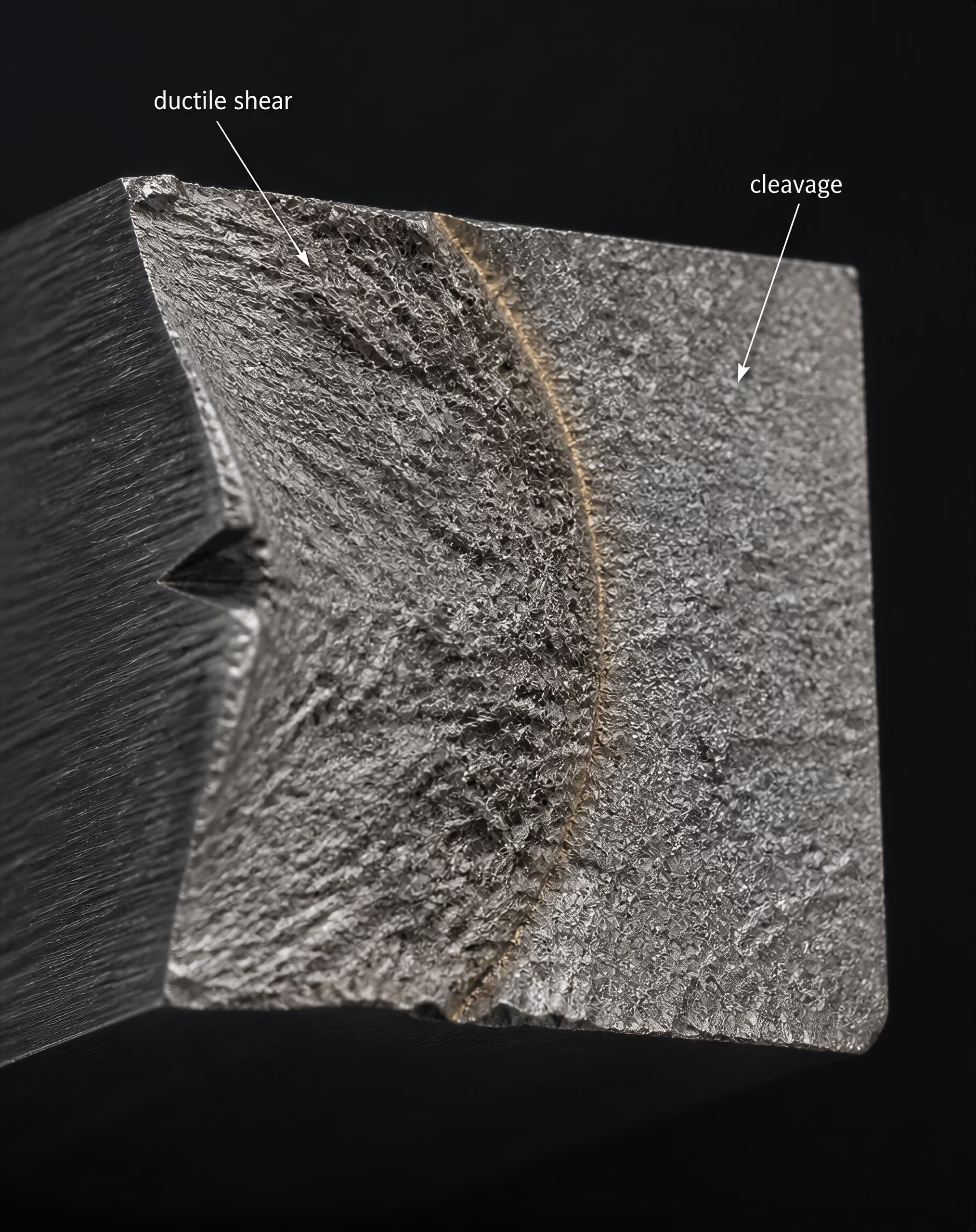
A ductile-shear region usually has a fibrous, dull, or torn appearance. The crack advances through substantial plastic deformation, often by microvoid nucleation, growth, and coalescence. On a fracture surface, this mechanism can produce a rougher texture and slanted shear lips near the free surfaces. The corresponding test often records greater absorbed energy because the specimen deforms appreciably before complete separation.
Cleavage fracture is typically brighter and more crystalline-looking, with relatively flat facets and river patterns that indicate rapid crack propagation through preferred crystallographic planes. It involves much less macroscopic plastic deformation than ductile tearing. A cleavage-dominated surface commonly accompanies a low impact-energy result, but visual appearance must be interpreted with the specimen orientation, steel grade, temperature, notch condition, and examination method in mind. A fractured surface is not a complete metallographic diagnosis.
The transition is often mixed rather than abrupt. One specimen may contain ductile tearing at the outer surfaces and a cleavage region nearer the notch, or separate ductile and cleavage areas divided by a visible boundary. Reporting the fraction of shear fracture, often as a percentage of the fracture surface, can show that a material is moving through the ductile-to-brittle transition even when the energy values overlap. For example, two specimens can absorb similar energy while one has predominantly fibrous fracture and the other contains a substantial cleavage area; those results do not carry the same warning about low-temperature crack propagation.
Fracture appearance also helps expose scatter. Charpy energy is affected by notch acuity, local inclusions, grain structure, specimen orientation, and test temperature. A single average can hide a specimen with an unusually large cleavage region. Examination of the broken faces adds a physical check on whether the measured energy agrees with the expected failure mode.
This evidence should not be mislabeled as plane-strain fracture toughness. NIST describes Charpy testing as a high-loading-rate test that measures energy absorbed during fracture and provides an indirect measure of impact toughness. Correlations may estimate lower-bound fracture toughness for ferritic steels, but separate relationships apply to lower-shelf, transition-region, and upper-shelf behavior. A Charpy value is not a direct , , or crack-arrest measurement.
Shear-fracture appearance as a reported result
Shear-fracture appearance is a result reported alongside absorbed energy, test temperature, specimen orientation, and identification details. In standards-based work, the method used to determine the shear fraction matters; visual estimates, comparison procedures, and measurement conventions should not be mixed without stating the basis. The report should identify whether the specimen was a standard V-notch or U-notch configuration and whether any modification, such as side grooving, was present.
A rising shear fraction with increasing temperature generally supports a transition from cleavage toward ductile fracture. It does not establish a universal transition temperature by itself. Engineers may define a transition temperature from an energy criterion, a shear-area criterion, or a specified combination, and those temperatures need not be identical. The chosen criterion must therefore be stated.
Instrumented testing can provide additional information about loading and fracture events. ISO 14556:2023 covers instrumented Charpy V-notch testing and the equipment used to measure and record impact behavior; instrumented testing is outside ISO 148-1:2016. These methods can help distinguish initiation and propagation features, but they still require control of geometry, material condition, temperature, and orientation.
Sampling also affects interpretation. ASTM A673/A673M specifies sampling procedures for longitudinal Charpy V-notch testing of structural steel and distinguishes heat-testing from piece-testing frequencies. Thus, a fracture photograph and energy value describe a particular tested specimen; they do not automatically represent every plate, piece, or heat.
NIST findings on side-grooved Charpy specimens
NIST’s 2011 assessment of side-grooved Charpy impact testing found that side grooves change more than the outline of the specimen. At upper-shelf energies, they reduce the accumulation of plastic deformation and promote splitting. The reported splitting severity was greatest near the ductile-to-brittle transition temperature.
Splitting is a longitudinal separation or tearing feature that can develop ahead of, or alongside, the principal fracture path. Side grooves guide deformation and alter constraint across the specimen width, changing crack growth and the resulting fracture morphology. They can make the fracture surface appear more segmented and can affect the measured energy as well as the division between ductile and cleavage regions.
For that reason, side-grooved and conventional Charpy specimens should not be compared casually. The altered geometry changes constraint, plasticity, crack extension, and the opportunity for splitting. A side-grooved result may be useful for a defined research or qualification purpose, but it is not simply a sharper version of a standard result. Geometry, notch form, groove dimensions, orientation, temperature, and reporting method must match the intended comparison.
The NIST findings also reinforce the central limitation of impact energy: the number alone does not identify the fracture mechanism. Energy, shear area, cleavage features, and splitting should be read together, with the applicable standard and specimen design kept visible.
Instrumented Charpy Testing and What Extra Signals Can Show
Instrumented Charpy testing adds measurement channels to the ordinary pendulum impact test. Instead of recording only the hammer’s initial and final energy, the machine records the force applied to the specimen and its variation during the event. That extra record can show when the specimen begins to lose load-carrying capacity, how much work occurs before crack growth, and how the fracture develops after initiation. It does not turn a Charpy specimen into a conventional fracture-toughness specimen.
ISO 148-1:2016 specifies Charpy V-notch and U-notch pendulum impact testing for metallic materials, but instrumented testing is excluded from that method. The separate standard, ISO 14556:2023, specifies instrumented Charpy V-notch pendulum impact testing and the measurement and recording equipment used to obtain additional information about fracture behavior under impact conditions. ASTM E23 covers Charpy simple-beam and Izod cantilever-beam impact tests, including specimen requirements, procedures, machine verification, reporting, and determination of shear-fracture appearance; an instrumented result still depends on the applicable test standard and reporting requirements.

Force-time and energy-time information
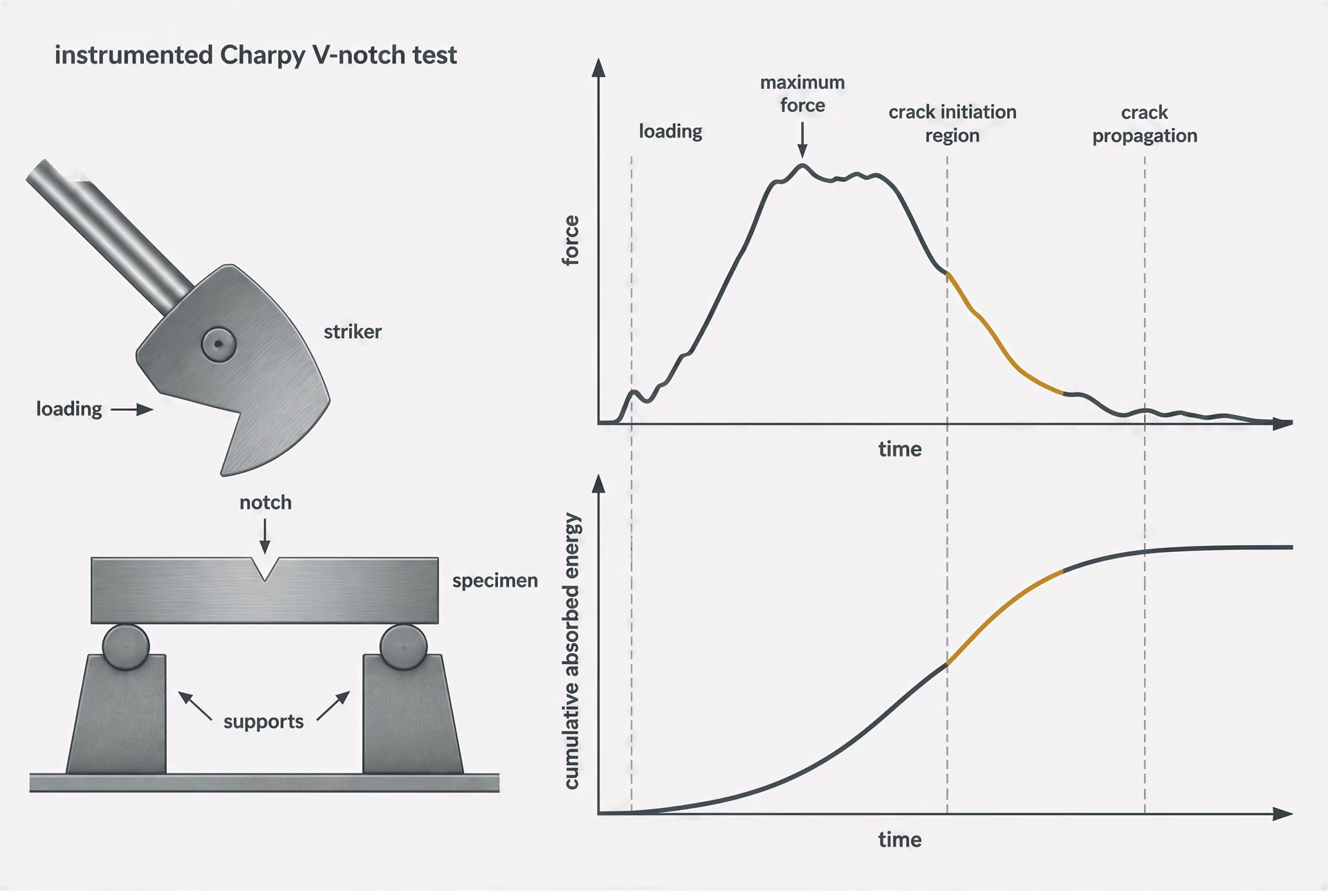
A conventional Charpy result is usually reported as absorbed impact energy, commonly in joules. NIST describes the Charpy test as a high-loading-rate test that measures energy absorbed during fracture and provides an indirect measure of impact toughness. Instrumentation adds a force-time trace, and often a force-displacement or force-energy trace, from which the total work can be calculated. In simplified terms, the area under a force-displacement curve is the mechanical work delivered to the specimen, while an energy-time curve shows how rapidly that work accumulates.
The shape of the curve matters. A steep initial rise can reflect elastic and plastic loading of the notched ligament. A maximum force may mark the point at which the specimen reaches its highest load, although maximum force is not automatically identical to physical crack initiation. A falling section may indicate crack growth, plastic collapse, striker contact changes, or a mixture of these effects. The signal must therefore be interpreted with the specimen geometry, striker configuration, span, impact velocity, and test temperature in view.
A meaningful trace begins with measurement quality. Force transducers, displacement or velocity measurement, timing, amplifier bandwidth, data-acquisition rate, and calibration all affect the recorded curve. Mechanical vibration can produce oscillations that resemble fracture events. Filtering can remove noise, but excessive filtering can also shift a peak or hide a short initiation event. Machine compliance and the mass of the striker influence the relationship between the recorded signal and the force actually carried by the specimen.
The integrated instrumented energy should also be checked against the machine’s conventional absorbed-energy result. Agreement is not guaranteed: friction, pendulum losses, fixture effects, calibration errors, and the chosen force-displacement reconstruction can produce differences. Periodic machine verification remains relevant. ISO 148-2 and ASTM E23 provide verification routes, including certified specimens in the Charpy Machine Verification Program described by NIST.
Initiation and propagation behavior under impact
One important use of the force record is separating the event into stages. Before a crack advances, the notched ligament may undergo elastic and plastic deformation. If a crack then initiates, the force-time curve may show a change in slope, a local maximum, a sudden drop, or another feature selected by the analytical procedure. The work up to the selected initiation point can be called initiation energy, while the remaining work is associated with subsequent crack propagation and specimen deformation.
Those terms describe an analysis, not an automatic physical truth. Crack initiation may occur before an obvious force drop, particularly when stable ductile tearing develops gradually. Conversely, a sharp signal change may result from a machine or contact effect rather than a newly formed crack. High-speed imaging, post-test fracture examination, compliance analysis, or supplementary sensors may be needed to confirm what a feature represents.
The distinction can be especially informative across the ferritic-steel ductile-to-brittle transition. At lower temperatures, cleavage can produce a rapid loss of load and relatively little deformation. At higher temperatures, ductile tearing and plastic deformation can consume more energy over a longer part of the trace. Fracture appearance supplies an essential check: shear and fibrous regions generally support a different interpretation from cleavage-dominated regions, even when two specimens have similar total energies.
Specimen orientation and material condition remain part of the result. ASTM A673/A673M specifies sampling procedures for longitudinal Charpy V-notch testing of structural steel and distinguishes heat-testing from piece-testing frequencies. A detailed force curve from one sampling location cannot establish behavior in every orientation, plate thickness, weld region, or heat-treatment condition.
NIST’s 2011 assessment of side-grooved Charpy specimens found that side grooves reduce plastic-deformation accumulation at upper-shelf energies and promote splitting, with splitting severity greatest near the ductile-to-brittle transition temperature. Such geometry changes can alter the force history and fracture appearance. They should not be treated as a minor modification when comparing datasets.
Limits of converting instrumented data into fracture toughness
Instrumented Charpy data can support fracture-mechanics calculations, but conversion requires a specified analytical procedure, validated calibration, and assumptions about crack geometry, deformation, loading rate, and material behavior. A force-time trace alone does not supply a valid critical stress-intensity factor, , or a valid plane-strain value.
A standard fracture-toughness test uses a fatigue-precracked specimen, controlled dimensions, crack-size measurement, validity requirements, and criteria for plane strain or elastic-plastic toughness. A machined Charpy V-notch has a different notch radius, ligament geometry, loading arrangement, and often a different constraint level. Dynamic loading further changes the material response. Even if an instrumented curve permits an estimate of initiation energy or a force associated with crack growth, that estimate is not automatically interchangeable with fracture toughness.
Charpy energy may be related to lower-bound fracture toughness for ferritic steels through specified correlations, but separate relationships apply to lower-shelf, transition-region, and upper-shelf behavior. Temperature, notch geometry, specimen orientation, fracture appearance, and material condition must accompany the number. Crack-arrest behavior is a separate question again: the drop-weight tear test characterizes pipeline-steel crack arrest through ductile-shear and cleavage fractions over impact temperatures, rather than by substituting its result for Charpy or fracture-toughness data.
Instrumented testing therefore adds evidence, not a universal conversion factor. Its strongest interpretation comes when the equipment is verified, the signals are clean and calibrated, the specimen and temperature are documented, and the initiation or propagation criterion is stated explicitly.
From Charpy Energy to Fracture Toughness and Crack Arrest
Charpy energy is not a fracture-toughness value. It is the energy absorbed when a standardized notched specimen breaks under a high-loading-rate pendulum impact. NIST describes the result as an indirect measure of impact toughness, not as a direct measurement of a crack-tip parameter such as , , or the crack-tip-opening displacement. The distinction matters because a small Charpy bar and a large cracked structural component experience different constraint, crack sizes, stress states, and plastic-zone dimensions.
ASTM E23 covers both Charpy simple-beam and Izod cantilever-beam impact tests, while ISO 148-1:2016 specifies Charpy V-notch and U-notch pendulum testing for metallic materials. Instrumented impact testing is separate: ISO 14556:2023 addresses instrumented Charpy V-notch tests and records force, displacement, and energy during fracture. Machine verification also affects confidence in the result. ASTM E23 and ISO 148-2 require periodic verification, including tests with certified reference specimens, and NIST operates a Charpy Machine Verification Program.
The reported joule value therefore describes a particular specimen, notch, orientation, temperature, test rate, and material condition. ASTM A673/A673M adds another qualification for structural steel: it specifies sampling procedures for longitudinal Charpy V-notch testing and distinguishes heat-testing from piece-testing frequencies. Sampling is part of the result’s meaning. A value from one selected specimen cannot automatically represent every plate, weld-adjacent region, rolling direction, or service temperature.
Conditional correlations for ferritic steels
For ferritic steels, Charpy energy can support an estimate of lower-bound fracture toughness when the correlation has been established for the relevant steel class and fracture regime. This is useful because ferritic steels commonly show a ductile-to-brittle transition as temperature falls. Their impact-energy curve may contain a lower shelf, a transition region, and an upper shelf, and the relationship between absorbed energy and fracture resistance changes across those regions.
Separate relationships apply to lower-shelf, transition-region, and upper-shelf behavior. A correlation selected for the upper shelf should not be applied to a lower-shelf result merely because both values are reported in joules. In the transition region, small temperature changes can produce large changes in fracture mode and measured energy, so the temperature at which the Charpy value was obtained is essential. The fracture appearance provides a second piece of evidence: cleavage-dominated fracture generally absorbs less energy, whereas ductile tearing usually produces greater plastic deformation and higher absorbed energy.
Even within ferritic steels, chemistry, grain size, strength level, heat treatment, plate thickness, rolling direction, notch acuity, and irradiation or thermal aging can alter the relationship. A correlation is thus a conditional model, not a universal conversion from joules to fracture toughness. It may provide a conservative screening estimate for a defined material population, temperature range, specimen orientation, and validity condition. It does not turn a routine Charpy result into a plane-strain fracture-toughness measurement.
The specimen itself can also affect interpretation. In a NIST study published in 2011, side-grooved Charpy specimens showed reduced accumulation of plastic deformation at upper-shelf energies and increased splitting; splitting severity was greatest near the ductile-to-brittle transition temperature. That finding reinforces the point: even a modified Charpy geometry can change the fracture process and cannot be treated as interchangeable with an ordinary V-notch specimen.
Lower-bound estimates and their limits
A lower-bound estimate is intended to avoid claiming more fracture resistance than the evidence supports. It can be appropriate for preliminary screening, integrity assessments with defined procedures, or situations where a code or regulatory practice specifically permits a Charpy-based relationship. The estimate must retain its conditions: material family, yield-strength range, orientation, temperature, notch configuration, energy range, and the fracture-toughness parameter being estimated.
The lower bound is not a guarantee that a component will resist every crack. Charpy specimens are small, and their fracture may occur with less constraint than a thick component containing a sharp fatigue crack. A structural crack can therefore experience a different stress field from the machined Charpy notch. Thickness, residual stress, weld defects, loading rate, crack size, and biaxiality may all reduce the relevance of a simple energy correlation. A value measured at room temperature also says little about behavior at a lower service temperature unless the transition curve has been established.
Fracture appearance and transition-temperature data should accompany the energy value whenever brittle-fracture risk matters. A single upper-shelf result may hide a steep transition at colder temperatures; a lower-shelf result may identify a condition where cleavage is already controlling. Direct fracture-toughness testing remains necessary when the assessment depends on a qualified , , or crack-tip-opening-displacement value under specified constraint and validity requirements.
How drop-weight tear testing differs
The drop-weight tear test answers a different question from Charpy testing. It was developed for pipeline-steel crack-arrest behavior, not simply for ranking small specimens by absorbed impact energy. A relatively long, notched strip is struck under controlled impact conditions, and the resulting fracture surface is examined over a range of temperatures. The assessment focuses on the proportions of ductile-shear and cleavage fracture, including whether a running fracture remains arrested as the fracture mode changes.
Charpy testing asks how much energy a standardized notched bar absorbs before fracture and may report absorbed energy, lateral expansion, and shear-fracture appearance. Drop-weight tear testing asks how a propagating fracture behaves in pipeline steel and how the fracture surface changes between ductile tearing and cleavage. The two tests may both reveal a ductile-to-brittle transition, but their geometries, specimen dimensions, loading responses, and engineering outputs differ.
Use Charpy testing to establish impact-energy and transition behavior for the specified material and orientation. Use a permitted Charpy correlation only for a stated, lower-bound fracture-toughness estimate. Use drop-weight tear testing when the engineering question concerns long-running fracture and crack arrest in pipeline steel. Neither result can answer the other question by itself.
References
- [1] ISO 148-1:2016 Metallic materials — Charpy pendulum impact test — Part 1: Test method. ISO standard, 2016. https://www.iso.org/cms/render/live/en/sites/isoorg/contents/data/standard/06/38/63802.html
- [2] ASTM A673/A673M: Standard Specification for Sampling Procedure for Impact Testing of Structural Steel. ASTM International standard, 2025. https://store.astm.org/a0673_a0673m-25.html
- [3] Charpy Machine Verification Program. NIST program resource, 2024. https://www.nist.gov/programs-projects/charpy-machine-verification-program
- [4] ISO 14556:2023 Metallic materials — Charpy V-notch pendulum impact test — Instrumented test method. ISO standard, 2023. https://www.iso.org/cms/render/live/en/sites/isoorg/contents/data/standard/08/21/82164.html
- [5] ASTM E23: Standard Test Methods for Notched Bar Impact Testing of Metallic Materials. ASTM International standard, 2025. https://store.astm.org/standards/e23
- [6] What fracture toughness can I assume for a ferritic steel if I know that it meets a certain Charpy energy requirement?. TWI Technical Knowledge, 2024. https://www.twi-global.com/technical-knowledge/faqs/faq-what-fracture-toughness-can-i-assume-for-a-ferritic-steel-if-i-know-that-it-meets-a-certain-charpy-energy-requirement
- [7] Side-Grooved Charpy Impact Testing: Assessment of Splitting and Fracture Properties of High-Strength Steels. NIST publication, 2011. https://www.nist.gov/publications/side-grooved-charpy-impact-testing-assessment-splitting-and-fracture-properties-high
- [8] What is the drop-weight tear test?. TWI Technical Knowledge, 2024. https://www.twi-global.com/technical-knowledge/faqs/faq-what-is-the-drop-weight-tear-test