



What Steel Creep and Stress Rupture Mean
Creep as time-dependent deformation
Steel creep is permanent, time-dependent deformation under an applied load at elevated temperature. The defining feature is not simply that the steel is hot or highly stressed; it is that strain continues to accumulate with time while the load and temperature remain sufficiently severe. A component can therefore change length, diameter, wall thickness, or alignment even when its applied stress remains below the short-term yield strength measured in an ordinary tensile test.
That distinction matters because yield strength is usually determined over minutes, whereas creep service may last for 10,000 or 100,000 hours. A steel that returns little or no permanent deformation during a short tensile test can still experience measurable elongation, local thinning, or distortion after years under load. At high temperature, dislocation movement, diffusion, grain-boundary sliding, and the growth or dissolution of precipitates allow deformation mechanisms that are too slow to appear in a conventional room-temperature test.
Key creep terms
- Primary creep
- Deformation begins at a decreasing strain rate as the material hardens.
- Secondary creep
- Strain proceeds at an approximately steady or minimum creep rate.
- Tertiary creep
- The strain rate accelerates as cavitation, cracking, section loss, or metallurgical degradation reduces load-bearing area.
How the creep curve develops
- Primary creep The strain rate decreases as strain hardening develops.
- Secondary creep Hardening and recovery approach balance and the minimum creep rate is observed.
- Tertiary creep Damage, localization, and section loss accelerate deformation until rupture.
A typical creep curve has three stages. Primary creep begins with a decreasing strain rate as the material hardens. Secondary creep follows with an approximately steady, or minimum, creep rate. Tertiary creep accelerates as cavitation, cracking, section loss, metallurgical degradation, or other damage reduces the load-bearing area. The curve is not a universal shape: its form depends on stress, temperature, grain structure, heat treatment, environment, and prior exposure.[1] ASTM E139-11(2018), Standard Test Methods for Conducting Creep, Creep-Rupture, and Stress-Rupture Tests of Metallic Materials. ASTM International. ASTM International standard, 2018. ASTM E139-11(2018)
ASTM E139-11(2018), published by ASTM International, provides the central test-method reference for metallic materials. It covers measuring deformation as a function of time in creep tests and measuring time to fracture in creep-rupture and stress-rupture tests under constant tensile force and constant temperature. A creep test may be stopped before fracture so that strain and creep rate can be evaluated. Its useful outputs include total strain, creep strain, strain rate, and the minimum creep rate.
NIMS reports Grade 91 creep-rupture strength across multiple product forms, temperatures, stresses, and rupture-life intervals. Strong evidence
The metallurgy can change during the test itself. In ferritic heat-resistant steels, carbide reactions, tempering, recovery, coarsening of strengthening particles, and loss of martensitic structure can alter the creep rate. Grade 91, commonly associated with 9Cr-1Mo-V-Nb steel, illustrates why a grade name alone does not define long-term behavior. NIMS’s 2024 Creep Data Sheet dataset covers Grade 91 tubes, plates, and pipe from 450 to 725 °C and 30 to 450 MPa, reporting creep-rupture strength at 100, 1,000, 10,000, and 100,000 hours. Those time points show the scale of the problem: the relevant property changes with the requested service life.
Creep also interacts with cyclic loading. K. Natesan’s IAEA discussion of Grade 91 ferritic steel identifies cyclic softening, strain-rate dependence, thermal aging, environmental effects, and microstructural change as factors in creep-fatigue design. A model developed by the authors of a 2022 Wilshire-equation and continuum-damage-mechanics study was intended to predict P91 creep deformation, minimum creep rate, damage, and stress-rupture life. The author names should be checked against the linked record before publication; they should not be inferred from the model description.
Stress rupture as time to fracture
Stress rupture describes the time required for a specimen or component to fracture under a sustained stress at a specified temperature. The result is a life-to-failure measurement, not merely a conventional tensile strength. A stress-rupture report should state the applied stress, temperature, rupture time, specimen orientation and geometry where relevant, and often the measured elongation and reduction of area.
| Aspect | Creep testing | Stress-rupture testing |
|---|---|---|
| Primary observation | Deformation as a function of time | Time required before fracture |
| Specimen outcome | May be stopped before fracture | Normally ends in fracture |
| Useful outputs | Total strain, creep strain, strain rate, minimum creep rate | Rupture time, elongation, reduction of area, fracture location |
The terms creep rupture and stress rupture overlap, but they emphasize different observations. Creep testing concentrates on deformation versus time, whether or not the specimen breaks. Stress-rupture testing concentrates on the duration before fracture, although the specimen normally undergoes creep before failure. ASTM E139 treats these related procedures within one framework.
Fracture mode is part of the result. A specimen may fail by ductile overload after substantial necking, by intergranular cracking associated with grain-boundary cavities, or by a more brittle path promoted by environmental attack or an unstable microstructure. Two tests with the same rupture time can therefore imply different service risks if one produces large prior deformation and the other produces relatively little warning before cracking.
NIST identifies creep-rupture data as a major class of mechanical-property information needed to evaluate metals at elevated temperature. NIMS maintains systematically collected data for carbon, low-alloy, high-chromium, and austenitic heat-resistant steels. Such data support extrapolation, but extrapolation is not a substitute for checking the actual steel condition, weld history, stress state, and exposure history.
Why temperature and sustained stress must be stated together
“High-temperature strength” is incomplete unless it includes both temperature and stress, along with a time basis. Increasing either temperature or sustained stress generally increases the creep rate and shortens rupture life, but the effect is strongly grade-dependent and is not captured by one room-temperature strength value. A statement such as “Grade 91 retains 500 MPa at high temperature” has no engineering meaning without the temperature, duration, allowable strain or damage limit, and test basis.
ASTM E139 assumes constant tensile force and constant temperature. Real components rarely experience that simple history. Pressure vessels, steam piping, headers, turbine parts, and reactor components may heat and cool repeatedly, experience start-up and shutdown transients, carry changing pressure, or develop thermal gradients and restraint stresses. These histories introduce creep-fatigue interaction, thermal stress, relaxation, ratcheting, and changing microstructure. A constant-temperature rupture curve cannot by itself describe those effects.[2] NUREG/CR-6150: Creep-Rupture Damage Modeling. U.S. Nuclear Regulatory Commission. U.S. Nuclear Regulatory Commission report, 1994. NUREG/CR-6150
Design rules convert test data into permitted stresses, life fractions, strain limits, or damage assessments. ASME BPVC Section II, Part D provides design material properties, while ASME BPVC Section III, Division 5 addresses construction rules for high-temperature reactor components. The European Union’s Directive 2014/68/EU requires creep-related material properties and prescribed limits to be considered for pressure equipment when creep is significant. NUREG/CR-6150, issued by the U.S. Nuclear Regulatory Commission in 1994, describes creep-rupture damage modeling with Larson-Miller and Manson-Haferd parameters for materials including carbon steel and stainless steel.
These parameters are methods of organizing data, not material constants that eliminate uncertainty. Long-term performance still depends on temperature history, sustained and cyclic stress, deformation rate, fracture mechanism, environmental exposure, and microstructural stability. That is why creep strain and stress-rupture life must be reported separately, then interpreted together for the actual service conditions.
The Three Stages of Creep Deformation
A creep test records strain against elapsed time while a specimen remains under sustained load and elevated temperature. The familiar result is an upward-curving strain–time plot: strain increases rapidly at first, the rate then becomes nearly steady, and deformation accelerates before fracture. This three-stage description is useful, but it is not a rule that every alloy, heat treatment, specimen, or loading history must follow. Some tests end during primary creep; others show only a short secondary region or pass directly into accelerating damage.
ASTM International’s ASTM E139-11(2018) specifies methods for measuring deformation as a function of time in creep tests and time to fracture in creep-rupture and stress-rupture tests on metallic materials under constant tensile force and temperature. A creep curve therefore describes more than “high-temperature strength.” It records how the material carries load, changes internally, and approaches failure.

Primary creep and decreasing strain rate
Primary creep begins when the applied stress and temperature produce time-dependent plastic deformation. The strain rate is initially relatively high, then decreases. This reduction commonly reflects strain hardening: dislocations multiply and interact, making further deformation more difficult. At the same time, recovery processes such as dislocation rearrangement and annihilation begin to counteract hardening. The measured curve is the result of those competing mechanisms.
The initial rate can also be affected by loading practice. A specimen brought quickly to the test temperature and force may show a different early response from one heated under load, because thermal expansion, transient stress redistribution, and microstructural recovery alter the starting condition. In precipitation-strengthened steels, particles may obstruct dislocation motion at first, then coarsen or dissolve during exposure. In ferritic heat-resistant steels, the stability of tempered martensite, carbide populations, and finer precipitates controls how quickly primary creep changes into a steadier regime.
Primary creep is not merely a short preface to the “real” test. The accumulated strain may matter in a component with a tight dimensional tolerance, and the early rate can reveal whether the material has been thermally aged or improperly heat treated. Grade 91, a 9Cr-1Mo-V-Nb steel, illustrates the point: its creep response depends on the stability of its tempered martensitic structure and precipitates, not only on its nominal chromium and molybdenum contents. Cyclic softening, strain-rate dependence, thermal aging, environmental exposure, and microstructural change are among the factors identified by K. Natesan of the IAEA in creep-fatigue design discussions for Grade 91 ferritic steel.
The curve may depart from the textbook shape when stress is low, temperature is changing, or a material undergoes strong structural recovery. A decreasing strain rate is usual, not universal.
Secondary creep and minimum creep rate
Secondary creep is the portion in which strain rate is approximately constant over a significant interval. In practice, the rate often reaches a minimum rather than remaining perfectly flat. This minimum creep rate is one of the most useful quantities for comparing alloys and test conditions because it provides a defined measure of deformation during the period when hardening and recovery are closer to balance.
The comparison is meaningful only when the test variables are controlled. Temperature, applied stress, specimen orientation, prior heat treatment, grain size, gauge length, and atmosphere can all change the measured value. A small change in temperature can produce a large change in rate because thermally activated diffusion and dislocation climb accelerate with temperature. Stress affects the rate through the active deformation mechanism; at different stress ranges, grain-boundary sliding, dislocation creep, or diffusion-assisted processes may dominate.
NIMS’s 2024 Creep Data Sheet database demonstrates why conditions must accompany any quoted value. Its Grade 91 dataset covers 450 to 725 °C and 30 to 450 MPa, with creep-rupture strength reported at 100, 1,000, 10,000, and 100,000 hours. Those intervals cannot be reduced to one temperature-independent strength number. NIMS also maintains systematically collected data for carbon, low-alloy, high-chromium, and austenitic heat-resistant steels.
Minimum creep rate is useful for model fitting as well as material comparison. A 2022 study reported through the U.S. Department of Energy’s Office of Scientific and Technical Information combined Wilshire equations with continuum damage mechanics to predict creep deformation, minimum creep rate, damage, and stress-rupture life in P91 steel. Such models still require data from relevant stresses, temperatures, product forms, and microstructural conditions. Extrapolating far beyond the tested range can hide changes in mechanism.
Specimen geometry matters here. Gauge length affects how local strain is averaged, while diameter and shoulder design influence stress concentration and heat flow. In a component, multiaxial stress, weld residual stress, notches, and internal pressure can produce a different local creep rate from that measured in a smooth uniaxial coupon.
Tertiary creep, damage accumulation, and rupture
Tertiary creep begins when the strain rate accelerates. The acceleration signals that the specimen is losing effective load-bearing area or that its internal resistance to deformation is deteriorating. Necking, grain-boundary cavitation, carbide coarsening, precipitate dissolution, oxidation, cracking, and localized deformation may act separately or together. As the effective section shrinks, the local stress rises even if the externally applied force remains constant. The curve then turns sharply upward and ends in rupture.
This stage is therefore a damage signal, not simply a faster version of secondary creep. A component can become unsafe before a visible crack appears, particularly when cavities form at grain boundaries or when a weld heat-affected zone weakens. The fracture mode depends on stress state, temperature, grain structure, environment, and exposure time. Smooth tensile specimens often fail by localized necking or intergranular cavitation; notched or constrained regions can experience high triaxiality and much earlier crack growth.
Stress rupture focuses on time to fracture, whereas creep testing emphasizes deformation as a function of time. The two measurements are related but answer different engineering questions. NIST identifies creep-rupture data as a major class of mechanical-property information needed to evaluate metals at elevated temperature. The U.S. Nuclear Regulatory Commission’s NUREG/CR-6150 (1994) describes damage modeling with Larson–Miller and Manson–Haferd parameters for materials including carbon steel and stainless steel, but parameterized curves remain dependent on the data and failure mechanisms behind them.
Design rules must account for that dependence. ASME BPVC Section II, Part D supplies design material properties, while ASME Section III, Division 5 contains construction rules for high-temperature reactor components. Directive 2014/68/EU requires creep-related material properties and prescribed limits to be considered where creep is significant in pressure-equipment design. These rules do not treat rupture time as a complete description of service performance. They also constrain allowable stress, deformation, damage, and lifetime under specified temperature and loading histories.
The end of tertiary creep is not always a single clean event. Thermal cycling can superimpose fatigue cracks; oxidation can reduce the section externally; and metallurgical aging can change the dominant mechanism during service. A reliable assessment therefore reads the full curve, identifies the minimum creep rate, examines the damage path, and checks whether the test specimen represents the component’s geometry, stress state, environment, and microstructure.
Metallurgical Mechanisms Behind High-Temperature Deformation
Creep is time-dependent deformation under sustained stress and temperature. Its familiar strain–time curve has three stages, but the stages are not separate laws of nature. They are the visible result of changing microscopic processes. Primary creep usually shows a falling strain rate as dislocations rearrange and the material hardens. Secondary creep has an approximately steady rate when hardening and recovery balance. Tertiary creep accelerates as necking, porosity, grain-boundary cavitation, cracking, and section loss reduce the load-bearing area.
Stress rupture asks a different question: how long does the specimen survive before fracture? ASTM E139-11(2018) specifies methods for measuring deformation with time in creep tests and time to fracture in creep-rupture and stress-rupture tests for metallic materials held under constant tensile force and temperature. A rupture time is therefore not a substitute for a creep curve. Two heats can reach fracture at similar times while accumulating different strains, or one can fail after modest overall strain because damage has localized at grain boundaries.

Dislocation motion and recovery
At temperatures below the range where diffusion is important, plastic strain is governed mainly by dislocation glide. A dislocation moves when the resolved shear stress overcomes resistance from the lattice, solute atoms, precipitates, other dislocations, and subgrain boundaries. Temperature changes this balance: thermal activation assists a dislocation in overcoming short-range obstacles, while sustained stress supplies the driving force for continued motion.
Dislocation climb Diffusion-assisted movement of a dislocation out of its original slip plane, allowing it to bypass obstacles that block ordinary glide.
At higher temperature, dislocations can climb as well as glide. Climb requires the diffusion of vacancies to or from the dislocation line, allowing it to move out of its original slip plane and bypass an obstacle. This process is central to power-law creep in many steels. A precipitate that blocks glide may be bypassed by climb; a dislocation pile-up can also relax when vacancies permit climb around an obstacle. The measured creep rate consequently depends on stress, temperature, obstacle spacing, vacancy mobility, and the evolving dislocation structure.
Recovery removes some of the hardening created by deformation. Dislocations annihilate when oppositely signed lines meet, rearrange into lower-energy configurations, and form subgrains through polygonization. These changes explain why primary creep can slow even while deformation continues: the material initially hardens, then recovery progressively offsets that hardening. In secondary creep, the balance between dislocation multiplication, glide, climb, and recovery produces a nearly constant minimum creep rate.
That balance is not fixed during service. Tempered martensitic Grade 91, also designated P91 in relevant product and design contexts, gains creep resistance from a fine lath structure and precipitates, including chromium-rich MC carbides and MX particles containing niobium and vanadium. Thermal exposure coarsens or redistributes these particles, alters lath and subgrain structures, and can reduce resistance to dislocation motion. K. Natesan’s IAEA discussion of Grade 91 identifies cyclic softening, strain-rate dependence, thermal aging, environmental effects, and microstructural change as design factors in creep-fatigue assessment. A specimen’s initial tensile strength therefore says little by itself about its long-term minimum creep rate after thousands of hours.
The dependence is often represented with a Norton-type relation, such as \(\dot{\varepsilon}=A\sigma^n\exp(-Q/RT)\), where creep rate increases with stress and temperature. It is useful over a defined mechanism and data range, not as a universal description. The stress exponent, activation energy, and even the controlling mechanism can change. The 2022 Wilshire-based continuum-damage-mechanics study of P91 illustrates this point by combining deformation and damage descriptions to predict creep strain, minimum creep rate, damage, and stress-rupture life rather than treating rupture strength as a single constant.
Diffusion, grain boundaries, and cavitation
| Mechanism | Diffusion path or action | Conditions or effect described |
|---|---|---|
| Nabarro–Herring creep | Diffusion through the crystal lattice | Atoms move from compression regions toward tension regions. |
| Coble creep | Diffusion along grain boundaries | Shorter boundary diffusion paths can increase deformation. |
| Grain-boundary sliding | Relative shear of adjacent grains | Requires accommodation by diffusion and dislocation activity. |
Diffusion-assisted deformation becomes increasingly important as temperature rises. In Nabarro–Herring creep, atoms diffuse through the crystal lattice from regions under compression toward regions under tension. In Coble creep, diffusion along grain boundaries provides a shorter path. Both mechanisms are strongly affected by grain size: finer grains offer more boundary area and shorter diffusion distances, which can increase diffusion creep under suitable conditions.
Grain boundaries are also sites of sliding. Neighboring grains can shear relative to one another when diffusion and dislocation activity accommodate the incompatibility at their junctions. Grain-boundary sliding contributes to creep strain particularly at high homologous temperature, low to moderate stress, and fine grain size. It cannot proceed indefinitely without accommodation; otherwise gaps and overlaps would form where several boundaries meet. Dislocation climb and diffusion supply that accommodation.
Grain-boundary cavitation The nucleation, growth, and linking of microscopic voids along grain boundaries under high-temperature stress.
The same boundaries can become the preferred sites for damage. Vacancies and impurities migrate toward stressed interfaces, while sliding concentrates strain at triple junctions and at particles. Small voids form, grow, and link into microcracks. This is grain-boundary cavitation. Tertiary creep begins when such damage, local necking, and crack growth reduce the effective cross-sectional area enough to accelerate the macroscopic strain rate.
Cavitation is affected by stress state, grain-boundary strength, particle distribution, oxidation, and prior thermal history. A uniaxial laboratory test does not reproduce every service condition: multiaxial constraint can suppress or promote void growth, and an oxidizing atmosphere can damage the surface and alter crack paths. ASM International’s discussions of creep and stress-rupture failures therefore treat environment, metallurgical instability, carbide reactions, fracture mode, and creep-fatigue interaction alongside stress and temperature.
NIMS provides systematically collected creep and rupture data for carbon, low-alloy, high-chromium, and austenitic heat-resistant steels. Its 2024 Grade 91 dataset covers 9Cr-1Mo-V-Nb steel tubes, plates, and pipe from 450 to 725 °C and 30 to 450 MPa, reporting creep-rupture strength at 100, 1,000, 10,000, and 100,000 hours. Those time intervals expose microstructural evolution that a short-duration tensile test cannot capture. NIST likewise identifies creep-rupture data as a major class of mechanical-property information needed to evaluate metals at elevated temperature.
The influence of grain size and crystallographic structure
Grain size changes the competition between intragranular deformation and boundary-controlled deformation. Coarse grains contain less total grain-boundary area, generally reducing boundary sliding and diffusion creep. This is why coarse-grained or directionally solidified structures can perform well in some high-temperature applications. Fine grains, however, can improve yield strength at lower temperatures through boundary strengthening and can help produce a uniform tempered-martensitic structure. The preferred grain size depends on the service temperature, stress, loading history, and failure criterion.
Crystal structure also matters. Ferritic and martensitic steels have body-centred cubic structures, while austenitic stainless steels have face-centred cubic structures. Their slip systems, diffusion rates, stacking-fault energies, phase stability, and precipitate reactions differ. A steel that resists dislocation glide at one temperature may soften through recovery or phase transformation during prolonged exposure. Grade C91 castings under ASTM A1091/A1091M rely on tempered martensitic or bainitic structures stabilized by precipitated particles, but the benefit depends on maintaining that particle-strengthened structure during service.
For design, mechanism changes cannot be hidden safely inside one extrapolation equation. NUREG/CR-6150 (1994) describes Larson–Miller and Manson–Haferd parameter methods for creep-rupture damage modeling in materials including carbon steel and stainless steel; these methods organize data but do not remove the need to check structure, environment, strain limits, and fracture mode. ASME BPVC Section II, Part D supplies design material properties, while Section III, Division 5 gives construction rules for high-temperature reactor components. The European Union’s Directive 2014/68/EU likewise requires creep-related properties and prescribed limits to be considered where creep is significant in pressure-equipment design. The correct interpretation begins with the mechanism controlling the curve, not with a single quoted “high-temperature strength.”
How Steel Microstructure Changes During Long Exposure
A steel component does not retain its manufacturing microstructure indefinitely. Temperature and stress continue to drive diffusion, dislocation recovery, particle growth, phase transformation, and damage accumulation after fabrication. The structure recorded by an acceptance test may therefore differ substantially from the structure controlling creep rate or fracture after 100,000 hours in service.
This distinction is central to ferritic creep-strength-enhanced steels. ASTM E139-11(2018), published by ASTM International, separates the measurement of deformation with time in a creep test from the measurement of time to fracture in a creep-rupture or stress-rupture test. Both results depend on the structure present during exposure, not merely on the initial tensile strength.

Tempered martensite and bainite in ferritic steels
Grade 91 long-term behavior depends on tempered martensite, precipitate stability, product form, heat treatment, and service exposure rather than nominal chemistry alone. Strong evidence
Grade 91 is a useful example. The designation commonly refers to the 9Cr-1Mo-V-Nb ferritic alloy family, supplied in product standards such as ASTM A213, ASTM A335, ASTM A387, and related specifications with the exact product form stated in each standard. After austenitizing, quenching or controlled cooling, and tempering, the alloy develops a tempered martensitic structure. Some ferritic creep-strength-enhanced steels, including Grade C91 castings covered by ASTM A1091/A1091M, may contain tempered martensitic or bainitic structures depending on composition and thermal history.
Features contributing to Grade 91 creep strength
- Tempered martensite Provides a high-dislocation-density matrix with lath or packet boundaries.
- M23C6 carbides Commonly decorate prior-austenite grain and lath boundaries.
- MX particles Fine vanadium- and niobium-containing carbonitrides remain dispersed within the laths.
- Boundary pinning Particles resist recovery and movement of boundaries and sub-boundaries.
Fresh tempered martensite contains high dislocation density, fine lath or packet boundaries, and a distribution of carbide or carbonitride particles. Bainite has its own lath arrangement and defect structure, but it also depends strongly on transformation temperature and subsequent tempering. These features obstruct dislocation motion and slow creep deformation. The strengthening is not supplied by chromium or molybdenum as isolated atoms alone; it comes from the combined effect of the matrix, boundaries, dislocations, and precipitated particles.
In Grade 91, chromium-rich M23C6 carbides commonly decorate prior-austenite grain and lath boundaries, while fine MX-type carbonitrides containing vanadium and niobium can remain dispersed within the laths. ASTM A1091/A1091M describes Grade C91 as having a tempered martensitic or bainitic microstructure stabilized by precipitated particles, with that stabilization contributing to creep-rupture strength. The particles pin boundaries and sub-boundaries, while the lath structure provides barriers to recovery.
That resistance is temporary rather than absolute. At service temperature, dislocations rearrange and annihilate, laths lose their original boundary character, and subgrains grow. The matrix gradually approaches a lower-energy configuration. As this recovery proceeds, the minimum creep rate can rise even when the applied stress and nominal temperature remain constant. A heat treatment that produces excellent short-term strength can therefore become less effective after prolonged exposure.
The NIMS Grade 91 dataset, reported by the National Institute for Materials Science in 2024, spans 450 to 725 °C and 30 to 450 MPa. It reports creep-rupture strength at 100, 1,000, 10,000, and 100,000 hours. Those time intervals are not interchangeable: a particle population that appears stable during a 1,000-hour test may coarsen enough to alter the 100,000-hour result.
Precipitation, coarsening, and carbide reactions
Precipitation strengthens ferritic steels only when particles have a suitable size, spacing, distribution, and interface with the matrix. Very fine MX carbonitrides can remain effective for long periods, whereas larger particles provide fewer obstacles per unit volume. Coarsening increases mean particle spacing and reduces resistance to dislocation motion. The material can soften without losing any obvious macroscopic feature such as surface cracking.
Carbide reactions add another layer of change. M23C6 particles may coarsen along boundaries, dissolve partially, or exchange elements with the ferritic matrix. New phases can form when elements such as molybdenum, tungsten, or other alloying additions become supersaturated during long exposure. In Grade 91, Laves-phase precipitation has been reported during aging under suitable conditions; its formation can initially affect strength and solute distribution, but continued growth may consume strengthening elements and promote local embrittlement or softening. The exact reaction depends on composition, prior heat treatment, temperature, stress, and exposure duration.
Particle stability also varies through the component. Weld heat-affected zones, casting segregation bands, grain-boundary regions, and areas near surfaces may begin with different precipitate distributions. In Grade C91 castings, solidification structure and local chemistry can produce regions that age at different rates. A single hardness value taken from an accessible surface cannot establish that every section has experienced the same metallurgical change.
Aged particles can also alter fracture behavior. Coarse boundary carbides and recovered lath structures reduce resistance to grain-boundary sliding and cavity formation. Under sustained stress, vacancies and deformation can concentrate at boundaries, where cavities nucleate around particles or inclusions. The eventual failure may be transgranular, intergranular, or mixed. Thus, precipitation hardening and stress-rupture resistance are related but not identical properties.
Thermal aging and metallurgical instability
Thermal aging includes the gradual structural changes caused by temperature alone, while creep adds stress-assisted diffusion, dislocation motion, and cavity growth. Oxidation, carburization, decarburization, and corrosive deposits can further modify the near-surface composition. These environmental effects may create a softened layer or brittle scale before the bulk steel has undergone equivalent aging.
Grade 91 is particularly sensitive to fabrication and service history. Incorrect normalizing or tempering can leave excessive delta ferrite, insufficiently tempered martensite, or an unsuitable precipitate population. During service, cyclic loading can produce cyclic softening, and the response depends on strain rate and temperature. K. Natesan of the IAEA identifies cyclic softening, strain-rate dependence, thermal aging, environmental effects, and microstructural change as factors in creep-fatigue design for Grade 91 ferritic steel.
This is why an as-manufactured certificate cannot by itself define long-term allowable performance. Metallographic examination, hardness mapping, replica measurements, weld assessment, and service exposure records may be needed to identify recovery, particle coarsening, or boundary damage. NIMS maintains systematically collected creep and rupture data for carbon, low-alloy, high-chromium, and austenitic heat-resistant steels; NIST describes creep-rupture data as a major class of mechanical-property information for evaluating metals at elevated temperature.
Design rules must account for the changing structure. ASME BPVC Section II, Part D supplies design material properties, while ASME Section III, Division 5 addresses construction rules for high-temperature reactor components. Directive 2014/68/EU requires creep-related properties and prescribed limits to be considered where creep is significant in pressure-equipment design. The U.S. Nuclear Regulatory Commission’s NUREG/CR-6150, published in 1994, discusses Larson-Miller and Manson-Haferd methods for creep-rupture damage modeling. Such parameters organize test data; they do not eliminate the need to check whether the aged microstructure remains comparable to the tested material.
Steel Families Used in Creep-Resistant Service
The National Institute for Materials Science (NIMS) Creep Data Sheet organizes long-term data into four practical steel groupings: carbon steels, low-alloy steels, high-chromium steels, and austenitic heat-resistant steels. These categories reflect different strengthening mechanisms and phase structures, not a simple scale from weak to strong. A steel may retain tensile strength at a given temperature yet accumulate unacceptable strain, or it may show modest creep deformation but fail by an environmentally assisted or microstructurally altered fracture mechanism.
Creep is time-dependent deformation under sustained stress and temperature. Stress rupture and creep rupture instead emphasize time to fracture, although the tests and data often overlap. ASTM E139-11(2018) specifies methods for measuring deformation with time in constant-force, constant-temperature creep tests and time to fracture in rupture tests. The distinction matters because a design can reach its allowable strain before rupture, while another component may remain dimensionally acceptable until a sudden grain-boundary failure.
Carbon and low-alloy steels
Carbon steels and low-alloy steels occupy the lower-alloy end of the NIMS database. Their structures commonly contain ferrite with pearlite, bainite, or tempered products formed during normalizing and tempering. Additions of molybdenum, chromium, manganese, and sometimes vanadium or nickel alter transformation behavior, carbide populations, hardenability, and resistance to softening. The strengthening available from these structures is useful at moderate elevated temperatures, but it declines as recovery, carbide coarsening, and diffusion accelerate.
Carbon steel does not lose all usefulness at temperature; its limits depend on stress, exposure time, section thickness, and the permitted deformation. NUREG/CR-6150, published by the U.S. Nuclear Regulatory Commission in 1994, describes creep-rupture damage calculations using Larson-Miller and Manson-Haferd parameters for materials including carbon steel and stainless steel. Such parameters are extrapolation tools, not substitutes for checking the test range, failure mode, and applicable design rules.
Low-alloy steels can extend the useful temperature range through solid-solution strengthening and more stable carbide distributions. Their performance still depends strongly on tempering condition. A normalized-and-tempered plate, a quenched-and-tempered forging, and a seamless tube with a different cooling history may share a nominal grade designation while having different prior-austenite grain sizes, banding, residual stresses, and precipitate distributions. Welding adds another variable: the heat-affected zone can have a different hardness and carbide structure from the parent metal, and it may control long-term deformation or rupture.
Service history continues the metallurgical process after fabrication. Prolonged heating can spheroidize pearlite, coarsen carbides, promote graphitization in susceptible carbon steels, and reduce strength. Repeated startups and shutdowns impose creep-fatigue damage rather than steady creep alone. Steam, combustion products, hydrogen, sulfur, and oxidizing gases can also change the surface and introduce defects that are not represented by an inert laboratory test.
High-chromium ferritic and creep-strength-enhanced steels
High-chromium ferritic steels use chromium for oxidation resistance and alloy additions for transformation control and precipitation strengthening. Conventional 9–12% chromium grades and creep-strength-enhanced ferritic steels have tempered martensitic structures containing a hierarchy of boundaries and particles. Grade 91, commonly designated P91 for pipe and T91 for tube in relevant pressure-equipment specifications, is a 9Cr-1Mo-V-Nb steel. Its long-term behavior depends on a tempered martensite lath structure supported by chromium-rich carbides, commonly described as M23C6, and fine MX carbonitride precipitates containing vanadium and niobium.
The NIMS Grade 91 dataset illustrates why one “high-temperature strength” number is misleading. The records cover 450 to 725 °C and 30 to 450 MPa, with creep-rupture strength reported at 100, 1,000, 10,000, and 100,000 hours (NIMS, 2024). Stress ranking can change with time and temperature because the laths recover, precipitates coarsen, and boundaries lose their ability to resist dislocation motion. At low stress and long duration, these changes may dominate the initial room-temperature strength.
Heat treatment is not a minor production detail for Grade 91. Normalizing establishes the martensitic starting structure; tempering controls hardness, residual stress, and precipitate development. Excessive tempering, incorrect austenitizing, or insufficient cooling can produce a structure outside the assumed material basis. Weld repairs and fabrication heat cycles are especially important. The fine-grained region of the heat-affected zone may experience accelerated creep and Type IV cracking, even when the parent plate or pipe meets its short-term specification.
ASTM A1091/A1091M addresses Grade C91 creep-strength-enhanced ferritic alloy steel castings for pressure-containing parts. The standard’s material concept depends on a tempered martensitic or bainitic structure stabilized by precipitated particles. Casting introduces its own concerns, including segregation, section-to-section cooling differences, porosity, and local variations in particle distribution. A cast component therefore cannot be assessed from nominal chemistry alone.[3] Wilshire-equation and continuum-damage-mechanics study of P91 steel. Authors to be verified against the linked record. U.S. Department of Energy Office of Scientific and Technical Information record, 2022. U.S. Department of Energy Office of Scientific and Technical Information linked record
A 2022 study recorded by the U.S. Department of Energy Office of Scientific and Technical Information combined Wilshire equations with continuum damage mechanics to predict creep deformation, minimum creep rate, damage, and stress-rupture life in P91 steel. That approach reflects the practical need to model several outputs at once. K. Natesan’s IAEA discussion of Grade 91 also identifies cyclic softening, strain-rate dependence, thermal aging, environmental effects, and microstructural change as variables in creep-fatigue design.
Austenitic heat-resistant steels
Austenitic heat-resistant steels rely on a face-centered-cubic matrix stabilized mainly by nickel, with chromium providing oxidation resistance. Common pressure and power-plant families include 304H, 316H, 321H, 347H, and higher-alloy grades such as 310H, although the applicable product and construction standards determine the exact designation and allowable use. Their austenitic phase remains stable over a broad temperature range, and their low transformation tendency supports service where ferritic steels would undergo phase-related changes.
Creep strength comes from solid-solution effects and precipitation. Carbon, nitrogen, niobium, titanium, and controlled boron can influence carbides, carbonitrides, and grain-boundary behavior. In stabilized grades such as 321H and 347H, titanium or niobium binds carbon, but exposure can still produce carbide redistribution, sensitization-related chromium depletion, sigma phase in susceptible compositions, or grain-boundary changes. Cold work may raise initial strength while increasing stored energy and recrystallization risk during service.
Austenitic steels also have higher thermal expansion and lower thermal conductivity than ferritic grades. Those properties affect thermal stress, restraint, weld design, and creep-fatigue interaction. Product form matters: sheet, plate, tube, bar, forging, and casting receive different thermal histories and may have different grain sizes or textures. Long service can further alter all of them through aging, oxidation, carburization, nitridation, or metal dusting.
For design, measured data must be interpreted through the governing rules rather than selected by grade name. NIST identifies creep-rupture data as a major category of mechanical-property information needed to evaluate metals at elevated temperature. ASME BPVC Section II, Part D supplies design material properties, while Section III, Division 5 gives construction rules for high-temperature reactor components. The European Union’s Directive 2014/68/EU likewise requires creep-related properties and prescribed limits to be considered where creep is significant. Temperature, stress, duration, environment, fabrication condition, and service history determine which portion of the data applies.
Grade 91 and P91: Reading the Evidence Correctly
9Cr-1Mo-V-Nb steel designations
“Grade 91” identifies a family of creep-strength-enhanced ferritic steels, not one universal product condition. The usual chemistry is described as 9Cr-1Mo-V-Nb: approximately 9% chromium, molybdenum, vanadium, and niobium, with controlled additions of nitrogen and carbon. Its useful high-temperature strength comes from more than nominal chemistry. The tempered martensitic structure contains a fine distribution of precipitates, including chromium-rich carbides and MX-type vanadium-niobium carbonitrides. These particles resist dislocation movement, while the lath structure and its boundaries provide additional resistance to creep deformation.
| Designation | Product form or use |
|---|---|
| T91 | Seamless ferritic and austenitic alloy-steel boiler, superheater, and heat-exchanger tubes under ASTM A213 |
| P91 | Seamless ferritic alloy-steel pipe for high-temperature service under ASTM A335 |
| Grade 91 | Pressure-vessel plate under ASTM A387 |
| C91 | Creep-strength-enhanced ferritic alloy-steel castings for pressure-containing parts under ASTM A1091/A1091M |
The designation changes with the product standard. ASTM A213 uses T91 for seamless ferritic and austenitic alloy-steel boiler, superheater, and heat-exchanger tubes. ASTM A335 uses P91 for seamless ferritic alloy-steel pipe intended for high-temperature service. ASTM A387 uses Grade 91 for pressure-vessel plates. ASME material specifications may reproduce these designations as SA-213 T91, SA-335 P91, and SA-387 Grade 91.
That distinction matters. “P91” commonly describes a pipe product, or a component made and specified as P91; it does not automatically describe every 9Cr-1Mo-V-Nb specimen. “Grade 91” is often used as a broader material family description, particularly in discussions of plate, tube, and normalized-and-tempered steel. A test report that says only “Grade 91” has not yet supplied enough information to establish equivalence with a P91 pipe in service. Heat number, product form, wall thickness, manufacturing route, weld condition, austenitizing treatment, tempering treatment, and post-weld heat treatment can all change the result.
The same caution applies to C91. ASTM A1091/A1091M covers Grade C91 creep-strength-enhanced ferritic alloy-steel castings for pressure-containing parts. C91 is not simply another spelling of P91. Casting solidification, segregation, section size, and heat treatment create a different evidence base, even when the intended creep-strength mechanism involves a tempered martensitic or bainitic structure stabilized by precipitated particles.
Tube, plate, and pipe data
| Dataset attribute | Reported coverage |
|---|---|
| Material | 9Cr-1Mo-V-Nb steel |
| Product forms | Tubes, plates, and pipe |
| Temperature | 450 to 725 °C |
| Stress | 30 to 450 MPa |
| Rupture-life reporting | 100, 1,000, 10,000, and 100,000 hours |
The National Institute for Materials Science (NIMS) Creep Data Sheet database provides a useful central case because it separates systematically collected long-term data for carbon, low-alloy, high-chromium, and austenitic heat-resistant steels. Its 2024 dataset for 9Cr-1Mo-V-Nb steel includes tubes, plates, and pipe. The tested temperature range is 450 to 725 °C, and the stress range is 30 to 450 MPa. Creep-rupture strength is reported at 100, 1,000, 10,000, and 100,000 hours.
Those reporting intervals are not four interchangeable “strength values.” Each represents an extrapolated or observed position on a time-dependent relation between stress, temperature, deformation, and fracture. A stress that survives 100 hours may be unacceptable at 100,000 hours. At a fixed stress, increasing temperature accelerates deformation and damage; at a fixed temperature, reducing stress can move the expected rupture time by orders of magnitude. NIMS therefore provides a field of evidence, not a single Grade 91 rating.
The distinction between creep and stress rupture must remain clear. ASTM E139-11(2018), issued by ASTM International, specifies methods for measuring deformation as a function of time in creep tests and time to fracture in creep-rupture and stress-rupture tests under constant tensile force and temperature. A creep test may emphasize strain, including the minimum creep rate and the transition from primary to secondary and tertiary creep. A rupture test emphasizes time to fracture, elongation, reduction of area, and fracture location. A material can show acceptable rupture life while accumulating an unacceptable amount of strain before rupture. Conversely, a component can fail a deformation limit without approaching tensile fracture.
NIST identifies creep-rupture data as a major class of mechanical-property information needed to evaluate metals at elevated temperature. That is why the NIMS intervals should be read with the test definitions, specimen dimensions, heat treatment, and failure criteria in view. They are not substitutes for a design code’s allowable stress tables.
Tube, plate, and pipe results should not be merged casually. Tube is often produced by piercing, extrusion, or cold working followed by solution treatment and tempering; its deformation history and wall-thickness gradients can differ from those of hot-rolled plate. Pipe may be seamless or welded, with different residual stresses, geometry, and inspection requirements. Plate has its own rolling texture, through-thickness variation, and section-size effects. Even when all three meet a nominal Grade 91 chemistry, their prior austenite grain size, martensitic lath arrangement, precipitate population, and impurity distribution may differ.
Specimen orientation also matters. A longitudinal tube specimen does not necessarily represent a transverse plate specimen, while a small laboratory sample may not reproduce the thermal history of a thick pressure component. Weld metal and heat-affected zones require separate evidence. Type IV cracking, which develops near the edge of the fine-grained heat-affected zone in some Grade 91 weldments, can control service life even when the parent metal has satisfactory creep-rupture strength.
Why product form and heat treatment affect results
Grade 91 depends on a carefully controlled normalized-and-tempered condition. Normalizing forms the prior austenite structure; tempering relieves some stresses and establishes the carbide and carbonitride population that supports long-term strength. Excessive tempering can coarsen precipitates and reduce resistance to creep. Insufficient tempering can leave excessive hardness, residual stress, and susceptibility to cracking. The relevant temperature, holding time, cooling rate, and section thickness therefore belong beside the grade designation in any serious comparison.
Long exposure also changes the structure. Carbide reactions, precipitate coarsening, lath recovery, thermal aging, cyclic softening, and environmental effects alter both minimum creep rate and rupture life. K. Natesan’s IAEA discussion of Grade 91 creep-fatigue design identifies strain-rate dependence, cyclic softening, thermal aging, environmental effects, and microstructural change as interacting factors. A constant-load rupture curve cannot capture every one of them.
The Wilshire-based continuum-damage-mechanics study reported through the U.S. Department of Energy in 2022 illustrates the modeling problem: its model combines Wilshire equations with continuum damage mechanics to predict creep deformation, minimum creep rate, damage, and stress-rupture life for P91 steel. Such a model is more informative than fitting one straight line through rupture points, but it still depends on material condition and valid calibration data. Larson-Miller and Manson-Haferd parameter methods, discussed for creep-rupture damage modeling in U.S. Nuclear Regulatory Commission NUREG/CR-6150 (1994), also compress temperature-time behavior into useful engineering forms; they do not remove uncertainty in extrapolation.
Design rules finally decide how laboratory evidence becomes a permissible stress or life limit. ASME BPVC Section II, Part D supplies design material properties, while ASME Section III, Division 5 addresses construction rules for high-temperature reactor components. Directive 2014/68/EU requires creep-related properties and prescribed limits to be considered where creep is significant in pressure-equipment design. The defensible question is therefore not “How strong is Grade 91?” It is: which product, in which heat-treated condition, at what temperature and stress, for how long, under which deformation and fracture criterion, and interpreted by which design rules?
Creep Testing Under ASTM E139
ASTM E139-11(2018), published by ASTM International, establishes procedures for determining the time-dependent deformation of metallic materials under sustained tensile loading and elevated temperature. It also covers creep-rupture and stress-rupture tests, in which the principal result is the elapsed time before fracture. The test therefore supplies a controlled material response, not a universal “high-temperature strength” value.
That distinction matters. A creep test can show how quickly a specimen extends, whether its deformation rate decreases or increases, and when fracture occurs. It does not guarantee that a pressure vessel, tube, casting, weld, or turbine component will survive for the same period. Service conditions may include multiaxial stress, thermal gradients, weld residual stress, oxidation, corrosion, vibration, load cycling, start-up and shutdown transients, and local geometric concentrations. ASTM E139 controls important variables, but it cannot reproduce every feature of an operating component.

Test specimen, load, and temperature control
The test begins with a machined tensile specimen taken from a defined product form, orientation, heat, and condition. Diameter or thickness, gauge length, surface finish, and any heat treatment must be recorded because these details affect both deformation and fracture. A Grade 91 tube, plate, and pipe can have different prior processing, texture, wall thickness, and microstructure even when all are identified as 9Cr-1Mo-V-Nb steel. Results from one form should not be transferred to another without metallurgical and design justification.
The specimen is installed in a creep frame that applies a sustained tensile force. ASTM E139 describes testing under constant tensile force and temperature; the reported nominal stress is calculated from the specified initial cross-sectional area and applied force. The machine must hold the force without unintended relaxation, shock loading, or substantial eccentricity. Alignment is critical. Bending superimposed on tension can accelerate deformation on one side of the gauge section and produce a misleadingly short rupture time.
Temperature control is equally important. A furnace surrounds the gauge length, while calibrated thermocouples monitor the specimen or its immediate vicinity. The test report should identify the target temperature, measured temperature, temperature tolerance, thermocouple locations, heating rate where relevant, and the time at which the specimen reached the test condition. A few degrees can alter diffusion, recovery, precipitate stability, and creep rate, particularly during long exposures. Temperature uniformity along the gauge length must be demonstrated rather than assumed. A hot end and a cool end create a nonuniform stress-temperature history that is not represented by the nominal test temperature.
The stated stress and temperature define the result. NIMS’s 2024 Grade 91 Creep Data Sheet dataset illustrates the point: it covers 9Cr-1Mo-V-Nb steel from 450 to 725 °C and 30 to 450 MPa, with creep-rupture strength reported at 100, 1,000, 10,000, and 100,000 hours. Those values are a structured map of a particular alloy family, product condition, stress range, temperature range, and test method. They are not one Grade 91 property.
Strain measurement and time-to-fracture records
In a creep test, extension is recorded as a function of time. The resulting curve commonly contains primary creep, in which the deformation rate falls; secondary or steady-state creep, in which the rate is relatively stable; and tertiary creep, in which damage and accelerating deformation precede fracture. The boundaries between these stages are not fixed material constants. They shift with stress, temperature, specimen condition, environment, and the chosen measurement method.
An extensometer measures gauge-length extension, usually through rods or other contacting elements connected to the specimen. Its gauge length, resolution, calibration, temperature capability, attachment method, and removal point must be documented. Some long-duration tests remove the extensometer before tertiary deformation or fracture to protect the instrument. If so, the report must identify the change in measurement practice and distinguish directly measured strain from later observations such as final elongation.
The data record should retain elapsed time, extension or strain, force, specimen temperature, and relevant instrument status. Sampling intervals need to capture the early transient without creating an unmanageable record over thousands of hours. A single minimum creep rate extracted from a curve is less informative than the curve itself, especially when the material shows a long primary stage or an abrupt tertiary stage.
For a creep-rupture or stress-rupture test, time to fracture is recorded along with the fracture location and mode. “Rupture life” is not the same as allowable service life. A specimen may fail by localized necking, internal cavitation, intergranular cracking, oxidation-assisted cracking, or a combination of mechanisms that differs from the expected component failure mode. Final elongation, reduction of area, fracture appearance, and metallographic observations help establish what the recorded time represents.
This is why NIST identifies creep-rupture data as a major class of mechanical-property information for evaluating metals at elevated temperature, while design rules require further interpretation. ASME BPVC Section II, Part D provides design material properties, and ASME Section III, Division 5 addresses high-temperature reactor construction rules. The European Union’s Directive 2014/68/EU likewise requires creep-related properties and prescribed limits to be considered when creep is significant in pressure-equipment design.
Repeatability, interruptions, and data quality
Repeatability depends on more than running two specimens at the same nominal stress and temperature. Specimens should come from comparable material, receive the same preparation, and experience equivalent loading and heating histories. Differences in grain size, tempering, precipitate population, decarburization, prior cold work, or weld location can produce real scatter. Grade C91 castings covered by ASTM A1091/A1091M, for example, depend on a tempered martensitic or bainitic structure and stabilizing precipitated particles; small changes in processing can alter long-term strength.
Every interruption requires a record. Power loss, furnace overshoot, extensometer removal, force drop, thermocouple replacement, machine shutdown, or temporary unloading can change the deformation history. The report should give the date and duration, stress and temperature before and after the event, reason for the interruption, and whether the test was resumed. A restarted test is not automatically equivalent to an uninterrupted exposure.
Quality review should compare force, temperature, strain, and elapsed-time channels for gaps or implausible jumps. The specimen should be inspected after failure, and deviations from ASTM E139 should be stated rather than hidden in a footnote. Long-term extrapolation also needs restraint. NUREG/CR-6150 discusses Larson-Miller and Manson-Haferd parameter methods for creep-rupture damage modeling, but such parameters summarize test data; they do not remove uncertainty in microstructural aging, environmental attack, or changing service stress. A Wilshire and continuum-damage-mechanics study reported in 2022 for P91 steel sought to predict creep deformation, minimum creep rate, damage, and stress-rupture life, showing why deformation and fracture need separate treatment.
The defensible statement from an ASTM E139 result is conditional: this specimen, in this material condition, sustained this stated tensile stress at this measured temperature, following this procedure, and produced this deformation history or rupture time. Anything broader requires evidence from additional tests and an applicable design rule.
From Creep Curves to Design Stress
Minimum creep rate and rupture strength
A creep curve records strain against time at a specified temperature and applied stress. Its familiar primary, secondary, and tertiary stages are useful descriptions, but they are not interchangeable design properties. The minimum creep rate, usually measured during the relatively steady secondary stage, indicates how quickly a component is accumulating permanent deformation. Creep-rupture strength instead describes the stress that produces fracture after a stated duration. A steel can therefore have an acceptable rupture life while accumulating too much strain, or show a low minimum creep rate yet suffer premature rupture because of defects, environmental attack, or an unstable microstructure.
ASTM International’s ASTM E139-11(2018) sets the testing framework for these distinctions. It covers measurement of deformation as a function of time in creep tests and measurement of time to fracture in creep-rupture and stress-rupture tests for metallic materials held at constant tensile force and temperature. The test result is not simply “high-temperature strength.” It is a point, or a curve, tied to temperature, stress, specimen geometry, material condition, and elapsed time.
| Steel grouping | Characteristics stated in the article |
|---|---|
| Carbon steels | Ferritic structures with pearlite, bainite, or tempered products; strength declines as recovery and diffusion accelerate. |
| Low-alloy steels | Alloy additions alter transformation behavior, carbide populations, hardenability, and softening resistance. |
| High-chromium ferritic steels | Tempered-martensitic structures use boundaries and precipitates for creep resistance. |
| Austenitic heat-resistant steels | Face-centered-cubic matrices rely on nickel stabilization, chromium oxidation resistance, and precipitation. |
For a material such as Grade 91, those qualifications matter. The National Institute for Materials Science (NIMS) Creep Data Sheet database contains systematically collected results for carbon, low-alloy, high-chromium, and austenitic heat-resistant steels. Its Grade 91 dataset covers 9Cr-1Mo-V-Nb steel tubes, plates, and pipe from 450 to 725 °C and 30 to 450 MPa, with creep-rupture strength reported at 100, 1,000, 10,000, and 100,000 hours (NIMS, 2024). Those four durations show why a stress suitable for a 100-hour test cannot be transferred casually to a 100,000-hour plant life.
The shape of the creep curve also exposes mechanisms that a single rupture point conceals. Tempered-martensitic Grade 91 depends on a fine distribution of precipitated particles and a stable substructure. Recovery, carbide or nitride reactions, thermal aging, cyclic softening, and prior fabrication history can change the minimum creep rate during service. ASTM A1091/A1091M, for example, specifies Grade C91 creep-strength-enhanced ferritic alloy steel castings for pressure-containing parts; its tempered martensitic or bainitic microstructure is stabilized by precipitated particles that increase creep-rupture strength. That benefit is conditional. Particle coarsening and substructure recovery can reduce it during long exposure.
The Wilshire-based continuum-damage-mechanics study reported through the U.S. Department of Energy’s Office of Scientific and Technical Information illustrates a more useful modeling aim for P91 steel: predicting creep deformation, minimum creep rate, damage, and stress-rupture life together. Such a model is more informative than fitting rupture life alone, although it still requires validation against the relevant heat, product form, stress range, temperature, and loading history. K. Natesan’s IAEA discussion of Grade 91 creep-fatigue design likewise identifies strain-rate dependence, thermal aging, environmental effects, cyclic softening, and microstructural change as variables that can alter service behavior.
Allowable stress and time-dependent criteria
Design stress is selected by comparing calculated component demands with several material limits, not by reading one number from a tensile-strength table. At elevated temperature, a code may restrict stress according to allowable total strain, minimum creep rate, rupture life, yield or proof strength, fatigue damage, local instability, or a prescribed fraction of a time-dependent material property. The controlling value can change with temperature and with the design life.
A thin pressure vessel illustrates the difference. If membrane stress is low enough to avoid immediate yielding but produces excessive creep strain, dimensional tolerances, valve alignment, or wall thinning may become unacceptable long before rupture. Conversely, a thick section may satisfy a strain limit while a notch, weld heat-affected zone, or multiaxial stress state controls the fracture assessment. Buckling and plastic instability can also control before either a creep-strain or rupture criterion is reached.
The European Union’s Directive 2014/68/EU, the Pressure Equipment Directive, requires creep-related material properties and prescribed limits to be considered where creep is significant in pressure-equipment design. The relevant question is therefore not merely whether a grade is labeled heat resistant. The designer must establish which ferritic or austenitic steel data apply, what temperature and duration govern, and which failure modes the conformity and design procedure must address.
ASME assigns this work to code-specific rules and tabulated properties rather than leaving it to an unrestricted extrapolation of laboratory curves. ASME BPVC Section II, Part D provides design material properties, while ASME BPVC Section III, Division 5 contains construction rules for high-temperature reactor components. These frameworks can impose limits based on allowable stress, creep strain, fatigue, creep-fatigue interaction, service duration, and damage accumulation. Their values should not be substituted across codes: an allowable stress calculated under one rule is not automatically acceptable under the Pressure Equipment Directive or a nuclear construction code.
NIST identifies creep-rupture data as a major class of mechanical-property information needed to evaluate metals at elevated temperature. That is why databases such as NIMS are valuable: they preserve the time, temperature, stress, product form, and material designation associated with each result. They do not eliminate engineering judgment. They make the basis for that judgment visible.
Safety margins and extrapolation limits
A safety margin is not a universal percentage applied after a test. It reflects uncertainty in material scatter, temperature measurement, stress analysis, weld quality, environmental exposure, load history, and the consequences of each failure mode. Codes convert those uncertainties into prescribed design values, reduction factors, life fractions, or separate limits. A component may need margin against both excessive deformation and rupture, with the lower permitted stress governing.
Interpolation within a qualified dataset is comparatively defensible. If Grade 91 results bracket the required stress, temperature, and duration, and the specimens represent the component’s product form and heat treatment, estimating a value between nearby observations can be supported by the observed trends. Even then, scatter bands and code procedures matter.
Extrapolation is different. Predicting 100,000-hour rupture life from a 1,000-hour test assumes that the same deformation and damage mechanisms continue for two additional orders of magnitude. That assumption can fail when precipitates coarsen, oxidation accelerates, or a new fracture mode develops. Larson-Miller and Manson-Haferd parameters, discussed for carbon steel and stainless steel in U.S. Nuclear Regulatory Commission NUREG/CR-6150 (1994), provide useful correlations, not physical permission to ignore mechanism changes.
A curve fitted beyond the tested temperature range is also risky. Temperature shifts can activate diffusion, recovery, phase transformation, or environmental reactions that were absent in the test. Long-term predictions should therefore be anchored by tests approaching the intended service duration and supported by microstructural examination, weld data, and periodic inspection. The design stress is credible only when its time, temperature, deformation, fracture, and code limits all match the service problem.
Long-Term Data Extrapolation and Parameter Methods
Long-term creep design often requires a prediction beyond the duration of available tests. A component may be expected to operate for 100,000 hours, while the test record contains only a few results at 1,000 or 10,000 hours. Parameter methods address this gap by compressing temperature and time into a single empirical quantity, allowing rupture data from several temperatures to be fitted together. They do not create new observations. They provide an extrapolation whose reliability depends on the test range, material condition, stress interval, and continued validity of the deformation mechanism.
This distinction matters because creep and stress rupture are related but different measurements. ASTM E139-11(2018), published by ASTM International, covers deformation as a function of time in creep tests and time to fracture in creep-rupture and stress-rupture tests under constant tensile force and temperature. A rupture-life curve therefore cannot, by itself, describe strain accumulation, minimum creep rate, tertiary damage, or the strain limit reached before fracture.
NUREG/CR-6150, issued by the U.S. Nuclear Regulatory Commission in 1994, describes creep-rupture damage modeling with Larson-Miller and Manson-Haferd parameters for materials including carbon steel and stainless steel. These methods are empirical curve-collapsing procedures. Their output can support engineering calculations, but it must remain tied to the material and test population from which the fitted constants were obtained.
Larson-Miller parameter methods
Larson–Miller parameter An empirical temperature–time parameter commonly written as P_LM = T(C + log10 t_r) for organizing creep-rupture data.
The Larson-Miller parameter is commonly written as
where is absolute temperature, is rupture time, and is a fitted material constant. Temperature may be expressed in kelvin or degrees Rankine, provided the same unit system is used consistently. The parameter is then correlated with stress, often through a polynomial, a piecewise fit, or a tabulated design curve.
The method assumes that combinations of temperature and rupture time producing the same value of have comparable rupture behavior at a specified stress. That assumption is convenient, not a metallurgical law. The constant is not universal for “steel”; it varies with alloy, heat treatment, stress range, fitting procedure, and sometimes the selected temperature interval. A curve fitted with one value of can appear orderly while a different value gives a substantially different long-time prediction.
Calibration must therefore be stated explicitly. The National Institute for Materials Science (NIMS) reports systematically collected creep and rupture data for carbon, low-alloy, high-chromium, and austenitic heat-resistant steels. Its 2024 Grade 91 dataset covers 9Cr-1Mo-V-Nb steel tubes, plates, and pipe from 450 to 725 °C and 30 to 450 MPa, with creep-rupture strength reported at 100, 1,000, 10,000, and 100,000 hours. Those reported durations are especially important: a fitted value at 100,000 hours is not equivalent to an actual 100,000-hour observation. If the 100,000-hour point exists for the relevant product form, temperature, stress, and heat treatment, it anchors the extrapolation. If it does not, the prediction remains model-dependent.
Larson-Miller fitting also tends to combine data across temperatures more readily than it reveals changes in mechanism. At shorter times, dislocation motion may dominate; at longer times, precipitate coarsening, grain-boundary cavitation, oxidation, or recovery may control life. Grade 91 illustrates the problem. Its tempered martensitic structure gains creep strength from fine precipitates and a stable substructure, but thermal aging and precipitate evolution can reduce that resistance. A single smooth line cannot announce when such a change occurs.
Manson-Haferd parameter methods
Manson–Haferd parameter An empirical parameter using fitted reference temperature and time values to organize rupture-life data across temperatures.
The Manson-Haferd parameter is commonly expressed as
where and are fitted constants associated with the apparent intersection of rupture-life trends. In contrast with Larson-Miller, the method does not impose a fixed additive constant inside . The fitted reference temperature and reference time are selected so that data from different temperatures collapse onto a useful stress-parameter relation.
Manson-Haferd fitting can perform better than Larson-Miller fitting over some datasets, particularly when the temperature dependence is not represented well by a fixed . It still assumes that the same relationship remains valid outside the measured range. The apparent intersection represented by and is a statistical construction, not necessarily a physical point in the alloy’s behavior. Changing the selected tests, stress range, or regression form can move those constants and alter the predicted life.
| Prediction method | Main quantity organized or predicted | Main limitation |
|---|---|---|
| Larson–Miller | Temperature, time, and rupture behavior | Can conceal changes in deformation or fracture mechanism. |
| Manson–Haferd | Temperature and rupture time through fitted reference values | Constants depend on the dataset and regression form. |
| Wilshire plus continuum damage mechanics | Creep deformation, minimum creep rate, damage, and stress-rupture life | Requires calibration and validation for the relevant material state and service range. |
Neither parameter method directly predicts the full creep curve. They primarily organize rupture time, usually , at a chosen stress and temperature. A design assessment also needs allowable stress, accumulated damage, deformation limits, and, where relevant, creep-fatigue interaction. NIST identifies creep-rupture data as a major class of mechanical-property information needed to evaluate metals at elevated temperature. The Wilshire-based continuum-damage-mechanics study reported through the U.S. Department of Energy Office of Scientific and Technical Information in 2022 takes a broader route for P91 steel, combining Wilshire equations with continuum damage mechanics to predict creep deformation, minimum creep rate, damage, and stress-rupture life. That approach addresses quantities a rupture-only parameter cannot supply, but it still depends on calibration data and material-state assumptions.
Model uncertainty and metallurgical breaks
A smooth fitted line can conceal large uncertainty. Logarithmic plotting compresses differences in time, and regression can make scattered results look orderly. The line may pass through the center of the dataset while missing the lower-bound behavior needed for pressure equipment or nuclear components. Scatter comes from heat-to-heat chemistry, prior processing, specimen size, surface condition, oxidation, weld history, and test alignment, not only from measurement error.
The main danger is a metallurgical break: a change in rate-controlling deformation or fracture process that invalidates the fitted relationship. Examples include carbide reaction, precipitate coarsening, loss of martensitic lath structure, grain-boundary cavitation, phase transformation, cyclic softening, or environmental attack. K. Natesan’s IAEA work on Grade 91 identifies cyclic softening, strain-rate dependence, thermal aging, environmental effects, and microstructural change as significant factors in creep-fatigue design. A long extrapolation that ignores them can be precise in appearance and wrong in mechanism.
Design rules place limits around this uncertainty. ASME BPVC Section II, Part D provides design material properties, while ASME Section III, Division 5 addresses construction rules for high-temperature reactor components. Directive 2014/68/EU requires creep-related properties and prescribed limits to be considered where creep is significant in pressure-equipment design. These rules should not be replaced by an unqualified parameter fit. Larson-Miller or Manson-Haferd results are evidence for a design decision, not direct observations at 100,000 hours unless such tests have actually been completed.
Damage Mechanics and Modern Rupture Prediction
Creep and stress rupture describe related but different outcomes. Creep is time-dependent deformation under sustained stress and temperature; stress rupture emphasizes the elapsed time before fracture. A sound prediction method must connect them rather than treat rupture life as an isolated number. ASTM E139-11(2018) sets the testing framework for measuring deformation with time in creep tests and time to fracture in creep-rupture and stress-rupture tests on metallic materials held under constant tensile force and temperature.
Continuum damage variables
Continuum damage mechanics represents distributed microstructural deterioration with one or more internal variables. A common scalar variable, , ranges from zero for an initially sound material toward one at rupture. It is not a direct measurement of the number of cavities or cracks. Instead, it is a calculated state variable that may represent reductions in effective load-bearing area, stiffness, or resistance to creep.
The effective-stress concept illustrates the approach. If the nominal stress is , a damaged section may be assigned an effective stress such as
As increases, the remaining material carries more stress, which accelerates creep strain and damage accumulation. A model can therefore couple a deformation law,
\[ \dot{\varepsilon}_c=f(\sigma_\mathrm{eff},T,\text{microstructure}), \]
with a damage-evolution law,
\[ \dot{D}=g(\sigma_\mathrm{eff},T,\dot{\varepsilon}_c,\text{state variables}). \]
The exact equations vary. Some formulations associate damage with grain-boundary cavity growth; others use accumulated creep strain, stress triaxiality, or a phenomenological rate law. A scalar variable can also conceal important distinctions between isolated cavities, linked cavities, transgranular cracking, and oxidation-assisted fracture. That limitation matters when a component experiences multiaxial stress, weld heat-affected zones, or cyclic loading.
The physical interpretation must remain tied to the material. In Grade 91 ferritic steel, tempered martensite, prior-austenite grain boundaries, and precipitates such as MC carbides and MX carbonitrides control the early creep response. Thermal exposure can coarsen or redistribute precipitates, reduce subgrain strength, and promote recovery. K. Natesan’s IAEA work on Grade 91 creep-fatigue design identifies cyclic softening, strain-rate dependence, thermal aging, environmental effects, and microstructural change as relevant variables. A damage parameter calibrated on stable laboratory material cannot simply be transferred to an aged weld or a component exposed to steam oxidation.
Wilshire-based prediction for P91
A 2022 study recorded by the U.S. Department of Energy’s Office of Scientific and Technical Information provides a useful example: it combines Wilshire equations with continuum damage mechanics to predict creep deformation, minimum creep rate, damage, and stress-rupture life for P91 steel. The linked record should supply the study’s author names before publication; names should not be inferred from secondary citations.
Wilshire-type relationships are often expressed using normalized stress and an activation-temperature term. In simplified form, a parameter may relate normalized stress to rupture time or minimum creep rate through a temperature-dependent exponential function. Unlike a single straight-line fit on a Larson–Miller plot, the Wilshire framework attempts to preserve a connection between stress relative to a material strength scale and the thermally activated processes controlling deformation. The continuum-damage component then gives the calculation a changing material state instead of assuming that the specimen remains unchanged until an abrupt final fracture.
That distinction is important for P91. The steel can show a long period of modest strain followed by accelerated deformation as recovery, precipitate evolution, cavitation, and local stress concentration progress. A model that predicts only the final rupture time may match a test table while missing the strain history, the minimum creep rate, or the onset of tertiary creep. The combined approach instead seeks consistency among four observables: the creep curve, the minimum creep rate, the growth of a damage variable, and the terminal rupture time.
The available NIMS Grade 91 database gives this task a demanding calibration space. Its 9Cr-1Mo-V-Nb steel records cover 450 to 725 °C and 30 to 450 MPa, with creep-rupture strength reported at 100, 1,000, 10,000, and 100,000 hours. NIMS also maintains systematically collected data for carbon, low-alloy, high-chromium, and austenitic heat-resistant steels. Those records are not interchangeable: a fit for P91 should not be presented as a general law for every high-chromium steel, much less for ASTM A1091/A1091M Grade C91 castings. Grade C91 castings use a tempered martensitic or bainitic structure stabilized by precipitated particles, but casting scale, segregation, and section size can alter damage development.
Minimum creep rate, damage, and rupture-life coupling
Minimum creep rate is often treated as a convenient correlation variable because it is comparatively easy to extract from a creep curve. It is more than that, but less than a complete damage measurement. A rising minimum creep rate may indicate weakening through recovery or precipitate degradation, yet two specimens with similar minimum rates can later fail by different mechanisms. One may develop grain-boundary cavities; another may suffer oxidation, weld-localized cracking, or a change in deformation mechanism.
A coupled model uses minimum creep rate as an observable linked to internal state. During primary creep, the rate generally decreases as the material hardens. In secondary creep, it reaches a low or nearly stable value. During tertiary creep, damage and localization cause the rate to rise. If the constitutive and damage laws reproduce these stages, integration of the equations can produce a predicted rupture time rather than merely fitting rupture time after the fact.
That prediction still depends on evidence. NIST identifies creep-rupture data as a major class of mechanical-property information needed to evaluate metals at elevated temperature, while the ASM International chapters on Creep and Stress Rupture Failures and Design for High-Temperature Applications stress deformation mechanisms, fracture, environmental effects, metallurgical instability, aging, carbide reactions, and creep-fatigue interaction. NUREG/CR-6150 shows how Larson–Miller and Manson–Haferd parameters can support damage modeling, but parameterized curves remain empirical summaries unless their assumptions are tested against changing microstructures and loading histories.
A model is only as credible as its calibration data, validation range, uncertainty treatment, and representation of service microstructure. Extrapolating from 10,000-hour tests to 100,000 hours is not automatically justified; neither is extrapolating from constant temperature and stress to a pressure cycle. ASME BPVC Section II, Part D supplies design material properties, and Section III, Division 5 sets construction rules for high-temperature reactor components. The European Union’s Directive 2014/68/EU likewise requires creep-related properties and prescribed limits when creep governs pressure-equipment design. These rules do not turn a fitted equation into a material law. They provide the boundary within which test data, damage assumptions, safety factors, and inspection strategy must remain defensible.
Creep-Fatigue Interaction and Thermal Cycling
A component rarely experiences the constant tensile force and constant temperature assumed by a conventional creep test. Steam pipes heat from ambient conditions, hold at operating temperature, change pressure, and cool again. Reactor components may undergo power ramps, shutdowns, refuelling outages, and local thermal shocks. Each event changes both stress and deformation rate. A steady-load creep curve therefore supplies necessary evidence, but it does not by itself predict life under starts, stops, load changes, or thermal cycling.
ASTM International’s ASTM E139-11(2018) defines methods for measuring deformation as a function of time in creep tests and time to fracture in creep-rupture and stress-rupture tests under constant tensile force and temperature. That controlled condition is useful precisely because it isolates a material response. It is not a description of every service history. NIMS data make the same point indirectly: the Grade 91 dataset spans 450 to 725 °C and 30 to 450 MPa, with rupture strength reported at 100, 1,000, 10,000, and 100,000 hours. Interpolating among those points cannot replace an assessment of transient strain, thermal gradients, hold periods, and cycle count.
Hold times and cyclic softening
A thermal cycle usually combines a fatigue-producing strain reversal with a creep-producing hold. During heating, restrained expansion can create compressive stress; during cooling, the same restraint can produce tensile stress. If the temperature remains high after the transient, stress relaxes through creep. The resulting hysteresis loop is not fixed from one cycle to the next.
Grade 91, also designated P91 or 9Cr-1Mo-V-Nb steel in appropriate product and construction contexts, commonly shows cyclic softening under strain-controlled conditions. Its initial tempered-martensitic strength decreases as repeated plastic deformation rearranges dislocations and as the lath structure changes. A softened material reaches a given strain range at a lower stress, but that does not mean damage has disappeared. Stress relaxation during a hold can increase accumulated inelastic strain, while cavitation at prior-austenite grain boundaries and lath or packet boundaries can continue during the apparently quiet portion of the cycle.
Hold time has two competing effects. It may reduce the tensile stress amplitude by relaxation, lowering the purely fatigue component. It also allows creep strain, oxidation, diffusion, and cavity growth to proceed. A tensile hold is often more damaging than a compressive hold because opening of grain-boundary cavities and oxidation-assisted cracking is favored during tensile loading. The effect depends on temperature, strain range, atmosphere, surface condition, and the preceding cycle; a universal “hours per cycle” conversion is not defensible.
Creep-fatigue interaction is therefore not proven by adding an independently measured fatigue life to an independently measured creep-rupture life. A linear damage sum such as a fatigue fraction plus a creep fraction can be used only when its calibration range, cycle definition, hold treatment, and failure criterion have been validated for the material and service history. Otherwise, it can conceal interaction terms. Fatigue cracking may expose fresh metal to oxidation, while creep can blunt, sharpen, or branch a crack depending on stress state and temperature.
The IAEA material associated with K. Natesan identifies cyclic softening, strain-rate dependence, thermal aging, environmental effects, and microstructural change as specific Grade 91 design factors. Those factors are coupled, not separate correction boxes. A long hold can alter the microstructure that controls the next rapid strain reversal.
Strain-rate dependence and thermal transients
The plastic and creep response depends strongly on how quickly strain is imposed. At a high strain rate, dislocations carry much of the deformation before diffusion-controlled creep can accommodate it. At a low rate, creep contributes during the ramp itself. The same total strain range can consequently produce different peak stresses, inelastic strains, and crack-growth rates.
Thermal transients add another complication: temperature is rarely uniform through a wall. A hot inner surface and cooler outer surface create a through-thickness thermal strain mismatch, while welds, bends, attachments, and thick sections produce local constraint. A temperature change that appears modest in the bulk may generate a severe local cycle. Rapid heating can place the surface in compression and the interior in tension; rapid cooling can reverse that arrangement. Stress redistribution then occurs through plasticity and creep, so an elastic thermal-stress estimate can become misleading during a long hold.
Temperature also changes material structure. Recovery of the tempered-martensitic lath network, coarsening or dissolution of MX carbonitrides, evolution of MC carbides, and formation of intermetallic phases can reduce creep strength or alter ductility. Thermal aging may change the response even when the applied stress is unchanged. Weld heat-affected zones can age differently from base metal, creating local strain concentration and premature cracking.
The environment participates in the mechanism. Steam oxidation can consume chromium-rich protective scales and produce oxide layers that crack or spall during cycling. Air oxidation, impurities, and sodium or lead-containing coolant environments can alter crack initiation and propagation. Surface oxide is not merely a cosmetic layer when the component is repeatedly strained.
A model must therefore track temperature history, stress or strain history, inelastic strain rate, hold duration, and evolving internal damage. The Wilshire-based continuum-damage-mechanics study reported through the U.S. Department of Energy Office of Scientific and Technical Information in 2022 combines Wilshire equations with continuum damage mechanics to predict P91 creep deformation, minimum creep rate, damage, and stress-rupture life. Its value is methodological: deformation and rupture are treated as related evolving states rather than as one isolated rupture number. The authors’ names should be checked against the linked record before publication rather than inferred.
Grade 91 design complications
Grade 91 obtains its high-temperature strength from a tempered-martensitic microstructure supported by chromium, molybdenum, vanadium, niobium, nitrogen, and controlled carbon additions. That structure is sensitive to heat treatment, welding, fabrication strain, and service exposure. Small deviations in normalizing and tempering can produce large differences in creep performance. The weakest region may be a weld metal, fine-grained heat-affected zone, or intercritical heat-affected zone rather than the parent plate or pipe.
Designers must also distinguish material designation from allowable construction rules. ASTM A1091/A1091M covers Grade C91 creep-strength-enhanced ferritic alloy steel castings for pressure-containing parts; its tempered-martensitic or bainitic structure is strengthened and stabilized by precipitated particles. That designation does not automatically establish the behavior of every Grade 91 tube, plate, pipe, weld, or casting under cyclic service.
ASME BPVC Section II, Part D supplies design material properties, while ASME BPVC Section III, Division 5 provides construction rules for high-temperature reactor components. The European Union’s Directive 2014/68/EU requires creep-related properties and prescribed limits to be considered where creep is significant in pressure-equipment design. NUREG/CR-6150, issued by the U.S. Nuclear Regulatory Commission in 1994, describes creep-rupture damage models using Larson-Miller and Manson-Haferd parameters for materials including carbon steel and stainless steel. Such parameters summarize long-term test data; they do not remove the need to evaluate transient strain and interaction.
For Grade 91, a defensible assessment must account for thermal cycling, cyclic softening, weld location, strain rate, aging, environment, and the selected failure rule. A rupture curve is evidence. It is not the component’s life.
Fracture Modes and Failure Investigation
Creep fracture is not a single appearance or mechanism. A component may fail after a long period of slow strain accumulation, after a shorter stress-rupture exposure, or through creep-fatigue interaction during repeated thermal and mechanical cycling. The fracture surface records the final stage, but the surrounding microstructure often records the earlier damage. ASM International’s treatment of creep and stress-rupture failures therefore considers deformation mechanisms, stress and temperature dependence, fracture morphology, environmental effects, metallurgical instability, aging, carbide reactions, and damage accumulation rather than assigning failure to “high temperature” alone.
ASTM E139-11(2018) separates the measurements involved: a creep test follows deformation as a function of time under constant tensile force and temperature, whereas creep-rupture and stress-rupture tests emphasize time to fracture under specified conditions. That distinction matters during investigation. A specimen that fractured at 10,000 hours does not by itself reveal whether its minimum creep rate was unusually high, whether a late acceleration occurred, or whether a local defect controlled failure.
Transgranular and intergranular rupture
Transgranular rupture passes through grains. At elevated temperature, it can result from plastic flow concentrated within grains, carbide cracking, oxide-assisted cracking, or repeated thermal and mechanical cycling. The fracture may show dimples from microvoid coalescence, cleavage-like facets, or a mixed morphology. A transgranular surface is not proof of overload: a creep-damaged component can accumulate substantial intragranular strain before the final crack advances rapidly.
Intergranular rupture follows grain boundaries and is strongly associated with grain-boundary sliding, vacancy diffusion, boundary weakening, and cavity formation. Under sustained stress, boundaries perpendicular or oblique to the principal tensile direction can accommodate local strain. If boundary particles, segregated impurities, oxidation, or a depleted precipitate population reduce cohesion, small cavities form more readily. Those cavities enlarge, link along the boundary, and produce a crack path that can extend through many grains.
The distinction is useful but not absolute. A crack can begin at a grain boundary, cross a grain, and return to another boundary. Weld heat-affected zones, cast structures, inclusions, and regions altered by service exposure commonly produce mixed transgranular-intergranular fracture. Ferritic Grade 91, or P91, adds another complication: its tempered-martensitic structure depends on a fine distribution of precipitates for creep strength, but thermal aging and unfavorable precipitate evolution can reduce resistance to boundary damage. NIMS’s 2024 Grade 91 database covers 9Cr-1Mo-V-Nb steel tubes, plates, and pipe from 450 to 725 °C and 30 to 450 MPa, with rupture strength reported at 100, 1,000, 10,000, and 100,000 hours. A fracture interpretation must be tied to the relevant temperature, stress, product form, and heat treatment within such data—not merely to the grade name.
Cavities, necking, and crack initiation
Creep cavities are usually microscopic at first. Diffusion and grain-boundary sliding drive vacancies toward stressed boundaries, while inclusions and precipitate interfaces provide favorable nucleation sites. With continued exposure, neighboring cavities grow and coalesce. The remaining ligament carries more load, creating local strain concentration. This positive feedback produces a damaged band, a macroscopic crack, and eventually section loss.
The same sequence can occur at a weld toe, under a surface oxide, beside an inclusion, or at a geometric transition where triaxial stress is high. Local necking may precede final rupture, although diffuse creep strain can make the component appear only moderately deformed. In thin sections, oxidation or corrosion removes load-bearing metal and raises the true stress in the remaining section. A nominally acceptable operating stress can consequently become a locally damaging stress.
A fracture surface may show dimples, boundary facets, oxidation products, or a narrow final overload zone. None is sufficient alone. The investigator should map cavity density and size away from the fracture, measure wall thickness, and determine whether damage is aligned with the principal stress. Cavities concentrated near a weld or along prior-austenite grain boundaries suggest a different history from uniform ductile thinning.
Stress history is equally important. Grade 91 can experience cyclic softening, strain-rate dependence, thermal aging, environmental effects, and microstructural change, factors identified by K. Natesan in IAEA work on creep-fatigue design. A constant-load creep model may therefore misrepresent a component subjected to start-ups, shutdowns, vibration, or thermal gradients. The Wilshire-based continuum-damage-mechanics study reported in 2022 combines Wilshire equations with damage mechanics to predict P91 creep deformation, minimum creep rate, damage, and stress-rupture life. Such models are more informative than assigning a failure mechanism from the last few millimetres of fracture surface.
Metallographic evidence after service exposure
A sound investigation begins with records: metal grade and heat treatment, operating temperature, pressure, load, transients, dwell periods, and any upset condition. Confirm the actual metal temperature, not only the control-room reading. Determine whether stress changed through pressure excursions, thermal restraint, thinning, or distortion. Then locate the fracture relative to welds, bends, attachments, supports, corrosion, and insulation.
Examine the fracture first with low-power methods, preserve deposits, and avoid cleaning that can remove oxidation or corrosion evidence. Cross-sections should then be prepared through the origin and through apparently unaffected material. Optical microscopy and scanning electron microscopy can reveal cavities, boundary separation, oxide penetration, inclusions, necking, and fracture mode. Hardness mapping, dimensional measurements, and chemical analysis help identify tempering, overheating, decarburization, or contamination. In Grade 91, characterize prior-austenite grain structure, martensitic lath condition, M23C6 carbides, and MX precipitates; over-tempering, coarsening, or loss of precipitate stability may explain reduced creep strength.
Compare the observed damage with qualified creep and rupture data. NIMS provides systematically collected data for carbon, low-alloy, high-chromium, and austenitic heat-resistant steels, while NIST identifies creep-rupture data as a major class of information for evaluating metals at elevated temperature. Larson-Miller or Manson-Haferd correlations, discussed for carbon and stainless steels in U.S. NRC NUREG/CR-6150 (1994), can support life assessment but should not replace material-specific evidence. Design rules also matter: ASME BPVC Section II, Part D supplies design material properties, and Section III, Division 5 addresses high-temperature reactor construction; Directive 2014/68/EU requires creep properties and prescribed limits where creep is significant. Visual appearance starts the inquiry. It does not finish it.
Environmental Effects at High Temperature
Creep resistance is not an isolated material property when steel operates in steam, combustion products, reactor coolants, or corrosive deposits. A specimen tested in clean laboratory air may retain a polished surface and its full cross-sectional area, while a component in service can lose metal, develop oxide cracks, absorb hydrogen, or experience local chemistry that changes both deformation and fracture. The measured creep rate and rupture life then describe only part of the engineering problem.
Oxidation and section loss
At high temperature, steel reacts with oxygen and water vapour to form oxide layers. Depending on alloy composition and temperature, these may include iron oxides, chromium-rich oxides, or more protective mixed scales. The scale is not simply a passive coating. It can crack during thermal cycling, spall under vibration, and expose fresh metal. Repeated oxidation and spallation reduce the wall thickness of tubes, pipes, headers, and pressure vessels.
That geometrical change increases the true stress carried by the remaining metal. A nominal stress calculated from the original wall thickness can therefore understate the stress late in service. Local wastage is more dangerous than uniform thinning because pits, grooves, and scale-break regions concentrate stress and provide sites for creep cavities or fatigue cracks. Even modest average section loss can produce a much larger reduction in local rupture life.
Oxidation also changes the surface from which cracks begin. Surface-connected defects can form at oxide-metal interfaces, at grain boundaries exposed by scale detachment, or beneath deposits that generate differential aeration. Thermal expansion differences between steel and oxide impose additional stresses during startup and shutdown. In ferritic steels, chromium depletion near an oxidized surface may reduce resistance to subsequent corrosion and alter the local microstructure. In austenitic heat-resistant steels, oxide growth and carburization or decarburization can modify the near-surface mechanical response.
The distinction between deformation and fracture remains important. ASTM E139-11(2018), issued by ASTM International, specifies methods for measuring deformation as a function of time in creep tests and time to fracture in creep-rupture and stress-rupture tests under constant tensile force and temperature. Such a test can establish a material’s minimum creep rate or rupture life, but it does not automatically include the wall loss and scale damage produced by years of plant exposure.
The ASM Handbook chapter on Design for High-Temperature Applications treats environmental effects alongside stress, temperature, metallurgical instability, and damage mechanisms for this reason. A design calculation that applies a laboratory rupture curve to the original section without an oxidation or wastage assessment can be unconservative.
Corrosion-assisted damage
Corrosion can accelerate high-temperature failure through mechanisms that are distinct from ordinary oxidation. Steam oxidation, sulfidation from sulfur-bearing combustion gases, carburization, metal dusting, nitridation, and molten-salt attack can each alter the surface and subsurface structure. The controlling reaction depends on gas composition, temperature, flow, pressure, deposit chemistry, and exposure time.
Sulfidation is particularly damaging where sulfur-containing fuels or deposits produce iron or chromium sulfides. These products may be less protective than chromium-rich oxides and can consume alloying elements needed for scale stability. Molten deposits containing vanadium, sodium, potassium, or chlorides may dissolve protective oxides and create rapidly advancing localized attack. In combustion systems, a tube can therefore experience both creep from internal pressure and external wastage from the fire-side environment.
Corrosion-assisted cracking changes the failure sequence. A pit or intergranular groove raises the local stress, while the corrosive environment weakens the crack tip or removes material from newly exposed surfaces. Under sustained load, this can produce an interaction among creep cavities, oxidation, and crack growth rather than a single mechanism. Hydrogen generated by corrosion may enter the steel and reduce ductility in susceptible conditions, although the degree of effect depends strongly on alloy, temperature, hydrogen activity, and microstructure.
Microstructural stability still matters. Grade 91 steel, also designated 9Cr-1Mo-V-Nb, depends on a tempered martensitic structure and stable precipitates for creep strength. Thermal aging, cyclic softening, precipitation changes, and environmental attack can act together. NIMS’s 2024 Grade 91 Creep Data Sheet covers tubes, plates, and pipe from 450 to 725 °C and 30 to 450 MPa, with rupture strength reported at 100, 1,000, 10,000, and 100,000 hours. Those data are valuable, but a Grade 91 component exposed to steam oxidation or corrosive deposits still requires an assessment of thickness loss and surface damage.
Environment-dependent interpretation of test data
Laboratory data should be matched to the environment represented by the design. NIMS systematically collects creep and rupture results for carbon, low-alloy, high-chromium, and austenitic heat-resistant steels; NIST identifies creep-rupture data as a major class of mechanical-property information needed to evaluate metals at elevated temperature. Neither database makes an environmental correction automatically.
The ASM design guidance therefore supports one of two defensible approaches: test the material under service-relevant chemistry, or use clean-environment mechanical data together with a separately justified model for oxidation, corrosion, section loss, and crack growth. Exposure tests may need to reproduce steam pressure, combustion-gas composition, deposits, thermal cycling, and surface condition. Post-test metallography is essential when the environment can change fracture initiation.
For long extrapolations, the limitation is severe. A 10,000-hour rupture result in laboratory air cannot by itself validate a 100,000-hour component life in wet steam or sulfidizing gas. The Wilshire and continuum-damage-mechanics study on P91 steel predicts creep deformation, minimum creep rate, damage, and stress-rupture life, but environmental damage must be represented if it contributes materially to failure. NUREG/CR-6150’s Larson-Miller and Manson-Haferd methods likewise describe temperature-time relationships; they do not remove the need to assess corrosion and oxidation separately.
Design rules reflect this distinction. ASME BPVC Section II, Part D supplies design material properties, while ASME BPVC Section III, Division 5 addresses construction of high-temperature reactor components. Directive 2014/68/EU requires creep-related properties and prescribed limits where creep is significant in pressure-equipment design. These rules should not be read as permission to ignore service chemistry. Environmental exposure belongs in the test program, the damage model, or a conservative inspection and remaining-life calculation.
Codes, Regulations, and the Meaning of Allowable Stress
An allowable stress at elevated temperature is not simply the tensile strength of a steel divided by a safety factor. It is a code-defined design value derived from selected material data, temperature limits, construction assumptions, fabrication requirements, service duration, and permitted damage mechanisms. A value may control yielding at short duration, creep deformation over a specified period, or creep rupture at a specified life. Those are different checks.
ASTM E139-11(2018) separates the underlying measurements. The standard covers deformation as a function of time in creep tests, and time to fracture in creep-rupture and stress-rupture tests, for metallic materials held at constant tensile force and temperature. The resulting curves are evidence, not automatically design limits. NIST identifies creep-rupture data as a major class of mechanical-property information needed to evaluate metals at elevated temperature, while the ASM Handbook discusses the mechanisms that make extrapolation difficult: diffusion, dislocation motion, grain-boundary damage, environmental attack, metallurgical instability, aging, carbide reactions, and creep-fatigue interaction.
A code then converts selected evidence into rules. It may impose a lower stress than a laboratory curve suggests because the design must account for scatter, welds, forming, inspection, fabrication tolerances, transient operation, and uncertainty in long-term extrapolation. Conversely, a code value does not predict the exact remaining life of a particular vessel, tube, header, or reactor component. Compliance demonstrates that the specified design and construction satisfy the applicable rules; it is not a substitute for condition assessment, operating-history analysis, or a component-specific life assessment.
EU Pressure Equipment Directive 2014/68/EU
The European Union’s Pressure Equipment Directive 2014/68/EU establishes essential safety requirements for pressure equipment and assemblies placed on the European market. Its role is regulatory. It does not function as a single creep database or as a universal equation for remaining-life prediction.
For equipment operating in a temperature and stress range where creep is significant, the directive requires the designer to consider creep-related material properties and prescribed limits. Annex I addresses permissible stresses and requires appropriate material data for ferritic and austenitic steels, including consideration of creep strength and, where relevant, rupture strength. The design must prevent unacceptable deformation or rupture during the intended service period. That wording matters: the requirement is tied to the equipment’s design conditions, service life, materials, and failure consequences, not to a generic statement that a grade is “high-temperature steel.”
The directive also connects material selection to manufacturing and conformity assessment. A pressure part can require suitable material documentation, traceability, welding controls, heat-treatment records, and inspection. A creep calculation performed with room-temperature yield strength would miss the purpose of the requirement. At high temperature, the designer may need stress limits based on creep rate, creep-rupture strength, or a prescribed fraction of those properties, together with checks on local stresses and discontinuities.
NIMS illustrates the scale of the underlying evidence. Its 2024 Creep Data Sheet database contains systematically collected data for carbon, low-alloy, high-chromium, and austenitic heat-resistant steels. The Grade 91 dataset covers 9Cr-1Mo-V-Nb steel tubes, plates, and pipe from 450 to 725 °C and 30 to 450 MPa, with creep-rupture strength reported at 100, 1,000, 10,000, and 100,000 hours. Those intervals show why a single “creep strength” number is misleading. A stress that survives 100 hours may not satisfy a 100,000-hour design requirement.
ASME BPVC Section II, Part D
ASME BPVC Section II, Part D is primarily a materials-property and allowable-stress reference within the ASME Boiler and Pressure Vessel Code. It supplies tabulated design stresses, material specifications, stress–temperature information, physical properties, and related limits for materials accepted elsewhere in the construction code. It does not, by itself, define the complete construction procedure for every pressure boundary.
The tabulated value is the result of code methodology, not a direct reading of one test curve. Depending on temperature and material, the controlling basis can include yield strength, tensile strength, creep rate, or time-dependent rupture strength. The applicable construction section determines how that value is used, including rules for geometry, joints, welds, examination, pressure testing, and fabrication. Engineers must therefore match the material specification and product form exactly. Plate, pipe, tube, forging, casting, and weld metal may have different permitted values even when their nominal chemistry resembles the same grade.
Grade 91 demonstrates why product condition matters. Its tempered-martensitic microstructure depends on a controlled normalizing and tempering treatment, while vanadium–niobium carbonitrides and other precipitates help resist creep deformation. Thermal aging, improper heat treatment, welding, and extended exposure can change that structure. A tabulated Section II, Part D stress does not certify that an in-service Grade 91 component retains its original microstructure or remaining life.
Long-term data also require an extrapolation method. NUREG/CR-6150, published by the U.S. Nuclear Regulatory Commission in 1994, describes creep-rupture damage modeling using Larson–Miller and Manson–Haferd parameters for materials including carbon steel and stainless steel. Such parameters can organize test data across stress, temperature, and rupture time, but they remain models with a range of validity. The 2022 Wilshire-based continuum-damage-mechanics study of P91 steel goes further by combining Wilshire equations with damage mechanics to predict creep deformation, minimum creep rate, damage, and stress-rupture life. That kind of model supports assessment; it does not turn sparse data into certainty.
ASME BPVC Section III, Division 5
ASME BPVC Section III, Division 5 addresses construction of high-temperature reactor components. Its subject is not merely the tabulation of material strength. It provides rules for components exposed to elevated-temperature service, where creep, fatigue, creep-fatigue interaction, ratcheting, thermal gradients, and time-dependent damage can interact during operation.
Section III, Division 5 must be read alongside the applicable material requirements and property data, including the design values supplied through ASME BPVC Section II, Part D where applicable. The construction rules determine how designers evaluate temperature-dependent stresses, cyclic histories, strain limits, welds, inelastic analysis, and accumulated damage. A reactor component may experience startup and shutdown cycles superimposed on years of sustained temperature and pressure; a stress-rupture-only calculation would not capture that history.
The IAEA presentation by K. Natesan identifies cyclic softening, strain-rate dependence, thermal aging, environmental effects, and microstructural change as important factors in creep-fatigue design of Grade 91 ferritic steel. These concerns explain why a component can satisfy an allowable-stress calculation yet require surveillance or reassessment after service. The calculated margin belongs to the defined design basis.
That distinction is the central rule. Material data describe behavior under specified tests. Construction codes prescribe how designers and fabricators must use those data. Regulations establish legally enforceable safety requirements and conformity obligations. None of the three, alone or together, predicts every individual component’s remaining life. A credible life assessment must combine the code basis with actual temperature and stress histories, weld and inspection records, measured deformation, metallurgical condition, environmental exposure, and a failure-mode analysis that distinguishes creep deformation from creep rupture.
Remaining-Life Assessment of Aged Steel Components
Inspection data and service history
Remaining life is not a fixed property of a steel grade. It is an estimate for a particular component, stress history, temperature history, geometry, environment, and failure criterion. A useful assessment therefore begins with the operating record rather than with a handbook rupture curve.
Minimum inputs for remaining-life assessment
- Material identity Record grade, specification, heat number, product form, and heat treatment.
- Operating history Collect metal temperatures, gradients, pressure, load changes, startups, shutdowns, and trips.
- Condition evidence Map thickness, cracks, deformation, hardness, oxidation, replicas, and weld locations.
- Failure criterion Separate allowable deformation, leakage or instability, and rupture endpoints.
The record should establish the material designation, heat treatment, product form, wall thickness, weld procedure, filler metal, post-weld heat treatment, and any repair history. “Grade 91” is not enough by itself: tube, plate, pipe, weld metal, and heat-affected zone can show different creep behaviour. NIMS’s 2024 Creep Data Sheet database illustrates the range of evidence available. Its Grade 91 data cover 9Cr-1Mo-V-Nb steel tubes, plates, and pipe from 450 to 725 °C and 30 to 450 MPa, with creep-rupture strength reported at 100, 1,000, 10,000, and 100,000 hours. Those conditions are test points, not a prediction that every Grade 91 component will survive 100,000 hours.
Temperature history needs more than a design maximum. Logged metal temperatures, thermal gradients, burner or flow maldistribution, insulation changes, and periods of overheating can alter the result. A short excursion may have little effect on accumulated strain in one component yet accelerate oxidation, precipitate coarsening, or local damage in another. Start-ups, shutdowns, load changes, pressure cycles, and trips also matter because creep-fatigue interaction can concentrate damage during transients.
Stress history should include sustained pressure stress, weight and restraint loads, thermal stress, bending, nozzle loads, support displacement, and local stresses around weld toes, attachments, holes, and thickness transitions. Pressure alone rarely describes the highest stress. Dimensional records can reveal the accumulated response: diameter growth, bulging, bowing, thinning, distortion, permanent elongation, and changes in alignment. A stable dimension does not prove that no damage exists, but a rising dimensional rate is direct evidence that deformation is continuing.
| Inspection method | Evidence it can provide |
|---|---|
| Ultrasonic thickness measurement | Wall-thickness loss and local wastage |
| Surface crack examination | Surface-connected cracking and crack distribution |
| Replica metallography | Cavities, recovery, precipitate evolution, and creep cracks |
| Hardness mapping | Changes associated with tempering, recovery, cold work, or local weld condition |
| Fractography and metallography | Fracture mode, cavity linkage, oxidation, and damage origin |
Inspection findings then need to be mapped to the actual load path. Ultrasonic thickness measurements, surface crack examinations, radiography, phased-array methods, oxide measurements, hardness surveys, and replica metallography answer different questions. A wall-thickness loss calculation cannot account for creep cavitation at a weld unless the cavitation is separately detected. Likewise, a crack indication may control fitness for service before general creep strain becomes large.
The assessment should distinguish three endpoints: allowable deformation, leak or instability, and rupture. Stress rupture concerns time to fracture; creep assessment also concerns the rate and amount of deformation before fracture. ASTM E139-11(2018), published by ASTM International, defines testing under constant tensile force and temperature for measuring deformation with time in creep tests and time to fracture in creep-rupture and stress-rupture tests. A remaining-life calculation that uses rupture time as though it were a deformation limit answers the wrong question.

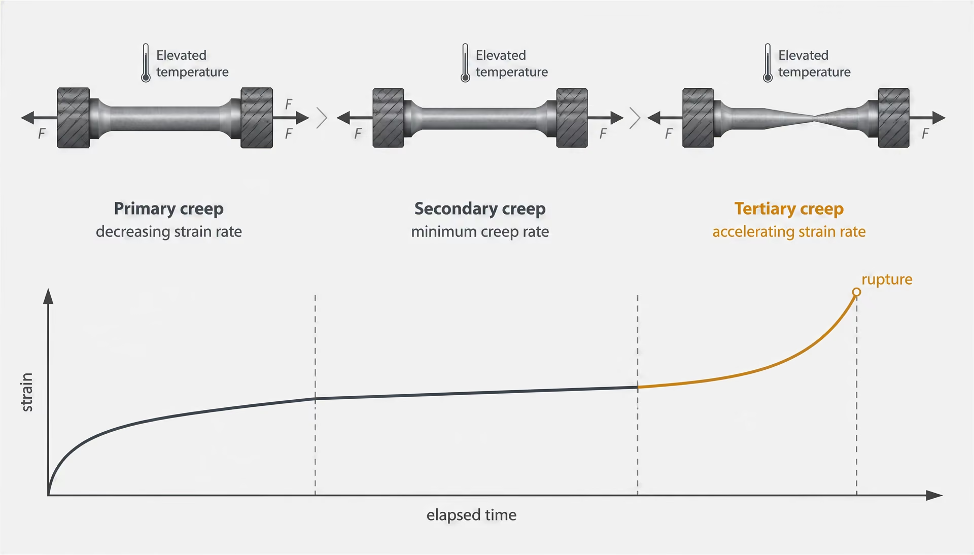
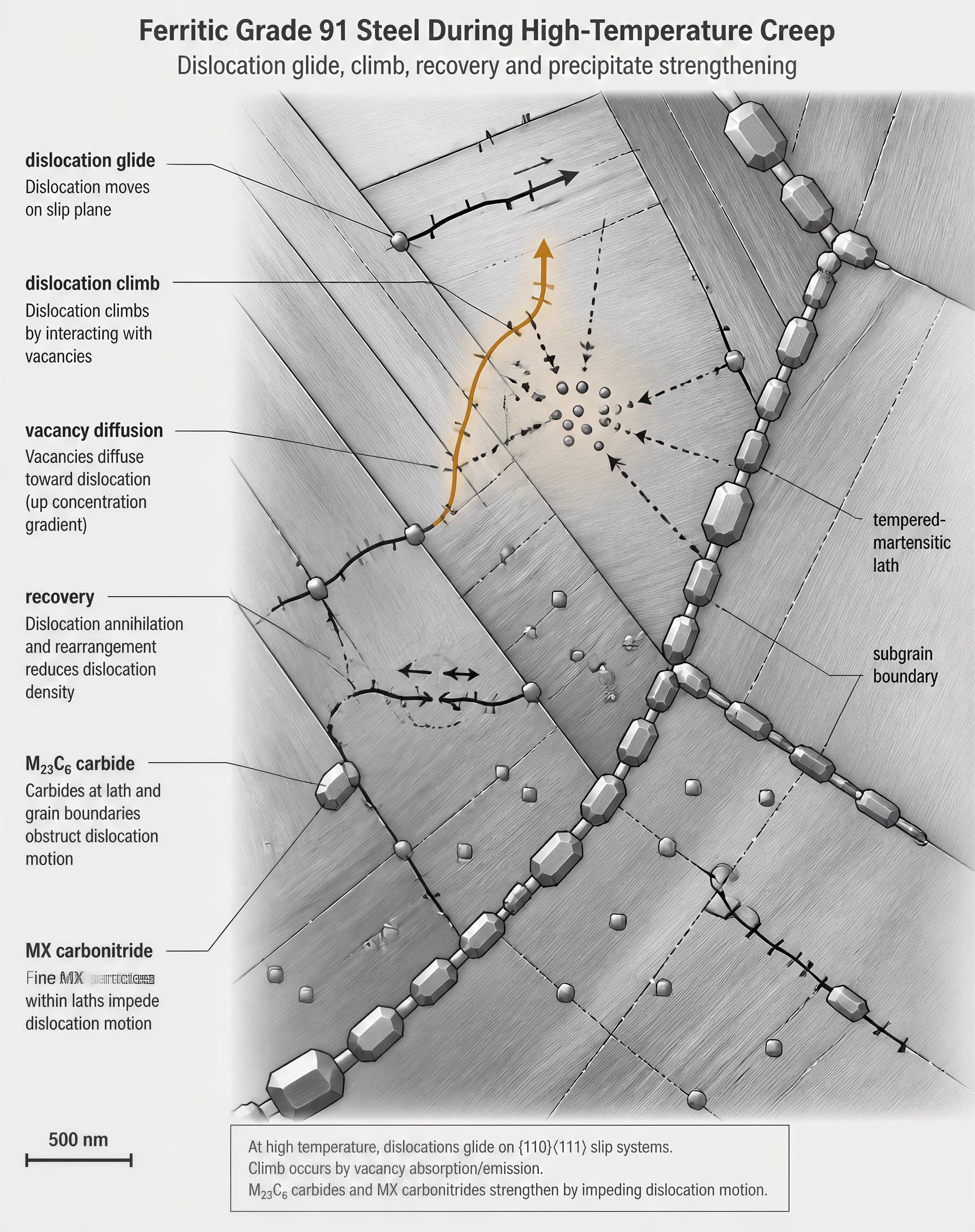
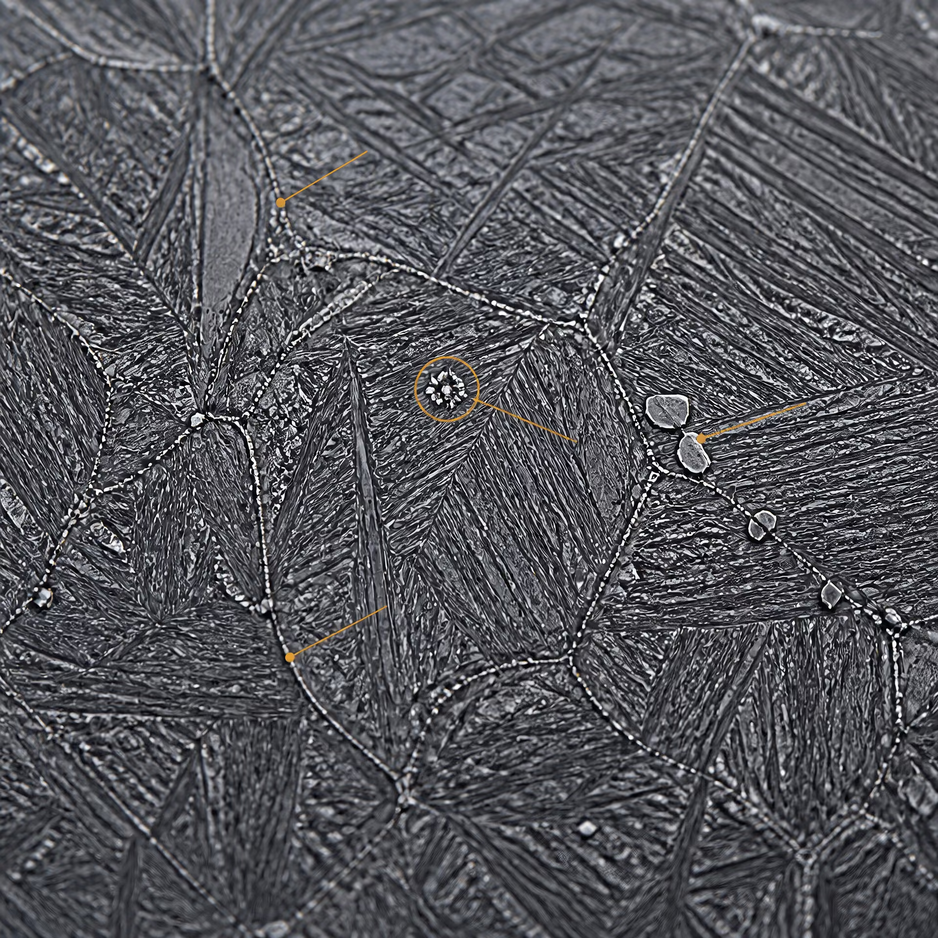
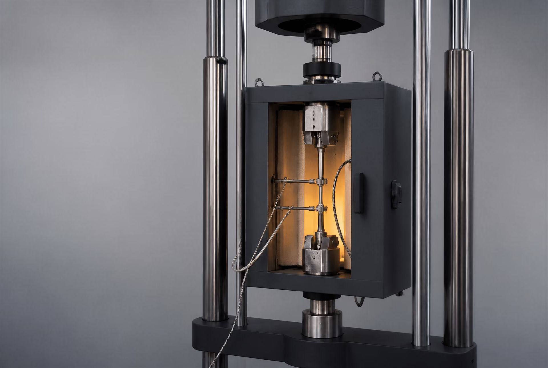
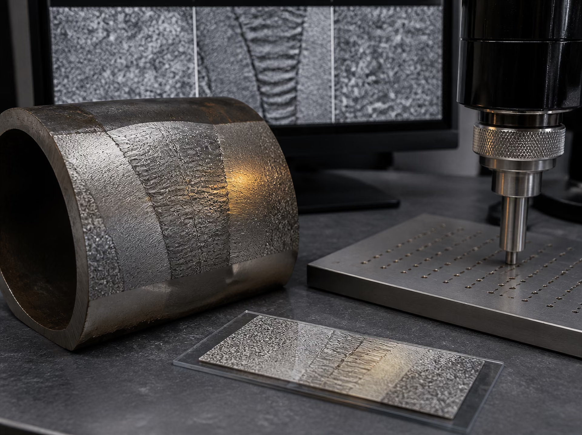
Replica metallography and hardness evidence
Replicas provide a practical way to examine surface microstructural change without removing a large sample. Properly prepared and indexed replicas can show carbide evolution, martensite or bainite recovery, precipitate coarsening, grain-boundary cavities, and creep cracks. The location matters as much as the image. Replicas from the parent metal, weld metal, and heat-affected zone should not be treated as interchangeable because thermal histories and precipitation reactions differ.
Replica metallography can identify service damage, but isolated cavities alone cannot establish remaining life. Limited evidence
For Grade 91 ferritic steel, long exposure can reduce the effectiveness of the tempered-martensitic structure through recovery, precipitate changes, and loss of subgrain stability. K. Natesan’s IAEA material on creep-fatigue design identifies cyclic softening, strain-rate dependence, thermal aging, environmental effects, and microstructural change as relevant factors. A replica showing isolated cavities is evidence of local damage, not by itself a remaining-life number. Cavity density, shape, alignment, crack linkage, affected area, and trend between outages provide stronger evidence.
Hardness is similarly useful but limited. A falling hardness can support evidence of tempering, recovery, or thermal exposure; a local increase may indicate a hard weld region, untempered martensite, cold work, or a repair condition. Hardness cannot uniquely determine creep strain or rupture life. It should be compared with documented fabrication values, nearby unaffected material, and results from the same component where possible.
Microstructural interpretation must also consider environmental damage. Oxidation, carburization, decarburization, hydrogen effects, and corrosion thinning can change both the measured section and the fracture mechanism. ASTM A1091/A1091M, for example, covers Grade C91 creep-strength-enhanced ferritic alloy steel castings for pressure-containing parts; its tempered martensitic or bainitic structure is stabilized by precipitated particles. That description does not make cast Grade C91 evidence interchangeable with wrought Grade 91 evidence.
A useful outage comparison records the same locations, magnification, preparation method, hardness method, and image scale. Repeated evidence can show whether cavities are stable, multiplying, or linking into cracks. It can also expose a dangerous assumption: apparently sound parent metal may coexist with a degraded weld heat-affected zone.
Reconciliation with creep-damage models
Models turn inspection and operating records into an estimate, but they do not replace engineering judgment about uncertainty. The first task is to select material data that match grade, product form, weld condition, temperature range, stress state, and environment. NIMS supplies systematically collected creep and rupture data for carbon, low-alloy, high-chromium, and austenitic heat-resistant steels. NIST identifies creep-rupture data as a major class of mechanical-property information needed to evaluate metals at elevated temperature.
NUREG/CR-6150, issued by the U.S. Nuclear Regulatory Commission in 1994, describes creep-rupture damage modelling using Larson-Miller and Manson-Haferd parameters for materials including carbon steel and stainless steel. Such parameter methods can interpolate and organize test data, but extrapolation over large changes in temperature, stress, microstructure, or time can be decisive. They should be treated as evidence within a defined data range, not as universal life predictions.
A calculation may integrate damage over changing conditions, compare predicted strain with measured dimensional change, and test alternative assumptions for local stress and temperature. The Wilshire-based continuum-damage-mechanics study reported by the U.S. Department of Energy Office of Scientific and Technical Information in 2022 combines Wilshire equations with continuum damage mechanics to predict creep deformation, minimum creep rate, damage, and stress-rupture life for P91 steel. Before publication, the study’s author names should be verified from the linked record rather than inferred. Its results still describe a model and dataset, not every P91 weld or service history.
Agreement between modelled strain and measured bulging is encouraging, but it does not validate rupture life automatically. Disagreement may identify an incorrect temperature, an underestimated local stress, material variability, weld degradation, or a different damage mechanism. A sound assessment reports these competing explanations and shows how the estimated interval changes when they are applied.
Design and regulatory rules define how evidence is interpreted. ASME BPVC Section II, Part D provides material properties, while ASME Section III, Division 5 addresses construction rules for high-temperature reactor components. Directive 2014/68/EU requires creep-related properties and prescribed limits to be considered where creep is significant in pressure-equipment design. Those rules constrain the assessment; they do not convert an inspection into a guaranteed service-life value. The defensible result is a documented range tied to observed condition, credible loading histories, material evidence, and a stated fracture or deformation limit.
How to Compare Creep Data Without Misreading It
Checklist for comparing creep data
- Material Grade, specification, product form, heat treatment, heat, and orientation.
- Loading Applied stress, stress definition, loading method, and geometry.
- Temperature Specimen or gauge temperature, control tolerance, and gradients.
- Measurement Strain method, gauge length, interruptions, and test duration.
- Outcome Rupture status, fracture location, fracture mode, and deformation history.
A creep curve is not a material constant. It is the response of a particular specimen, taken from a particular product and heat, tested at a stated temperature and stress for a stated duration. Before comparing two curves, record the complete test condition: steel grade and specification, product form, heat treatment, specimen orientation, gauge dimensions, applied stress and how it was calculated, test temperature and control tolerance, atmosphere, strain-measurement method, test duration, and whether the specimen fractured.
This distinction matters because creep is time-dependent deformation under sustained load and temperature, whereas stress rupture focuses mainly on time to fracture. ASTM E139-11(2018), published by ASTM International, covers measuring deformation as a function of time in creep tests and time to fracture in creep-rupture and stress-rupture tests under constant tensile force and temperature. A rupture-life curve therefore cannot answer a question about allowable strain unless accompanying deformation data exist. Nor can a short creep test establish a credible 100,000-hour service limit.
Stress, temperature, and rupture-time axes
Read both axes before reading the apparent ranking of curves. Rupture data are commonly plotted as stress against rupture time at fixed temperatures, but the presentation may be linear, logarithmic, or transformed through a parameter such as Larson–Miller or Manson–Haferd. A curve that looks nearly straight on one plot can change slope on another, particularly when the controlling mechanism changes from dislocation creep to diffusion-assisted deformation, grain-boundary damage, or precipitation instability.
Stress must also be defined precisely. Nominal engineering stress, true stress, and the stress calculated from the original or changing cross-sectional area are not interchangeable during tests with substantial deformation. Temperature is equally important. A difference of only a few tens of degrees can cause a large change in rupture life, while a temperature gradient through a thick specimen can produce a misleading average. Record whether the reported temperature is furnace, specimen, or gauge temperature.
The National Institute for Materials Science (NIMS) Grade 91 dataset illustrates the scale of the comparison problem. Its 9Cr-1Mo-V-Nb steel data cover 450 to 725 °C and 30 to 450 MPa, with creep-rupture strength reported at 100, 1,000, 10,000, and 100,000 hours. Those four time points are not interchangeable measures of “high-temperature strength.” A steel may retain a high stress at 100 hours yet fall sharply at 100,000 hours if its microstructure coarsens or its precipitates lose effectiveness.
Long-time values are often estimated from shorter tests using fitted equations. NUREG/CR-6150, issued by the U.S. Nuclear Regulatory Commission in 1994, describes Larson–Miller and Manson–Haferd approaches for carbon and stainless steels. Such parameters are interpolation tools, not permission to ignore changes in damage mechanism. A model combining Wilshire equations with continuum damage mechanics was reported in 2022 for P91 steel to predict creep deformation, minimum creep rate, damage, and stress-rupture life. Its purpose is to represent more than a single straight-line extrapolation.
Scatter, censored tests, and heat-to-heat variation
Creep data scatter because steels differ between heats, and because small differences in grain size, prior-austenite grain structure, carbide distribution, precipitate population, tempering, and cold work can alter both deformation rate and fracture mode. Grade 91 is a clear example: its tempered martensitic structure depends on normalizing and tempering practice, and long exposure can change lath structure and precipitates. K. Natesan of the International Atomic Energy Agency has identified cyclic softening, strain-rate dependence, thermal aging, environmental effects, and microstructural change as important factors in Grade 91 creep-fatigue design.
A test that has not fractured is not a failed data point. It is a censored observation: the specimen survived at least until the interruption time, but its eventual rupture life is unknown. Mark interrupted tests separately from actual rupture results. A curve fitted only to failed specimens can understate survival, while treating every interrupted test as though it fractured at the stop time can understate life. Report the reason for interruption too—equipment failure, scheduled removal, oxidation, leakage, or a planned inspection can carry different implications.
Do not confuse a mean trend with a design value. A regression through the center of a dataset describes expected behavior for the tested population; it does not provide a safe permissible stress. Design rules may apply lower-bound fits, scatter factors, minimum property requirements, damage fractions, or limits on total strain and rupture life. NIST identifies creep-rupture data as a major class of mechanical-property information needed to evaluate metals at elevated temperature. ASME BPVC Section II, Part D provides design material properties, while ASME Section III, Division 5 addresses construction rules for high-temperature reactor components. Directive 2014/68/EU likewise requires creep-related properties and prescribed limits where creep is significant in pressure-equipment design.
Tube, plate, pipe, casting, and weld comparisons
Product form is part of the material description. Tube, plate, and pipe may use different reduction ratios, heat treatments, wall locations, and sampling directions. A longitudinal tube specimen does not necessarily represent a transverse plate specimen. Thickness affects cooling rate and therefore grain size and precipitate distribution. Surface condition and decarburization can also affect a small rupture specimen disproportionately.
Castings require still greater caution. ASTM A1091/A1091M covers Grade C91 creep-strength-enhanced ferritic alloy steel castings for pressure-containing parts. Its tempered martensitic or bainitic microstructure is stabilized by precipitated particles, but casting segregation, porosity, section thickness, and local solidification structure create comparisons that cannot be made from grade name alone. “C91” casting data should not be placed directly against wrought Grade 91 tube data without checking specification, processing, heat treatment, and sampling location.
Welded components add several distinct populations: weld metal, fusion boundary, coarse-grained heat-affected zone, fine-grained or intercritical heat-affected zone, and unaffected base metal. The weakest region may control rupture even when the base metal curve looks favorable. Welding procedure, post-weld heat treatment, repair history, residual stress, and specimen notch location must therefore accompany the result.
Finally, reject two easy shortcuts. Room-temperature tensile strength does not predict long-term creep performance, and one short-duration rupture result does not establish a service ranking. Compare matching stress, temperature, time scale, product form, orientation, treatment, and failure location first. Only then should a curve be used for design.
Common Errors in High-Temperature Steel Selection and Analysis
Treating creep strength as a single number
A steel does not have one universal “high-temperature strength.” Its allowable stress depends on temperature, exposure time, stress state, strain limit, product form, microstructure, environment, and the failure mode being assessed. A short-term tensile result may describe resistance to rapid loading at 600 °C, but it cannot stand in for dimensional stability over 100,000 hours at the same temperature.
Creep and stress rupture are related but different measurements. Creep concerns time-dependent strain under sustained load; stress rupture records the time to fracture. ASTM E139-11(2018), ASTM International’s test standard, separates these purposes by covering deformation as a function of time in creep tests and time to fracture in creep-rupture and stress-rupture tests under constant tensile force and temperature. A component can therefore fail its design requirement through excessive strain, local instability, leakage, or loss of clearance before a rupture specimen would fracture.
The NIMS Grade 91 dataset illustrates why a single value is misleading. For 9Cr-1Mo-V-Nb steel tubes, plates, and pipe, the database spans 450 to 725 °C and 30 to 450 MPa, with reported rupture strengths at 100, 1,000, 10,000, and 100,000 hours. Those are not interchangeable points on one strength table. They describe a surface in stress-temperature-time space, and the relevant point must match the service history. NIMS also maintains systematically collected data for carbon, low-alloy, high-chromium, and austenitic heat-resistant steels; NIST identifies creep-rupture data as a major class of mechanical-property information needed to evaluate metals at elevated temperature.
Grade 91 exposes another frequent mistake: assuming that every product form behaves identically. Tube, plate, pipe, forgings, weld metal, and heat-affected zones can differ in prior-austenite grain size, tempering condition, precipitate population, residual stress, and processing history. P91 is a tempered-martensitic steel whose creep resistance depends strongly on its lath structure and precipitates. ASTM A1091/A1091M Grade C91 covers castings for pressure-containing parts, where a tempered martensitic or bainitic microstructure is stabilized by precipitated particles. “Grade 91” is not enough information for an assessment; the specification, product form, heat treatment, weld condition, and traceable test data matter.
Creep design should use time- and temperature-dependent, product-specific evidence rather than one high-temperature strength number. Strong evidence
The replacement for the single-number approach is a time- and temperature-dependent material model supported by product-specific data. Design values must then be taken from the governing rules, not reconstructed from an attractive tensile-strength figure. ASME BPVC Section II, Part D provides design material properties, while ASME BPVC Section III, Division 5 gives construction rules for high-temperature reactor components. Where creep is significant in pressure equipment, Directive 2014/68/EU requires creep-related properties and prescribed limits to be considered for ferritic and austenitic steels.
Ignoring time and transients
A constant-temperature, constant-load test is useful, but plant components rarely experience that history. Boilers, headers, reactor components, and steam piping undergo startup, shutdown, load changes, thermal stratification, vibration, and occasional overloads. These events alter stress and strain rates, produce thermal gradients, and can superimpose fatigue on creep.
Ignoring transients is particularly dangerous for Grade 91. K. Natesan’s IAEA material on creep-fatigue design identifies cyclic softening, strain-rate dependence, thermal aging, environmental effects, and microstructural change as important factors in ferritic Grade 91. A calculation based only on steady creep can miss relaxation during a hold, plastic strain during a rapid temperature change, or damage accumulated when a softened region attracts load.
Thermal aging also changes the material during service. Tempered martensitic steels may lose dislocation structure, coarsen or transform precipitates, and develop localized damage near welds. Carbide reactions and environmental attack can reduce resistance without any change to the nominal grade designation. The ASM International chapters on Creep and Stress Rupture Failures and Design for High-Temperature Applications place these mechanisms alongside deformation rate, fracture mode, metallurgical instability, environmental effects, and creep-fatigue interaction. They are not optional corrections applied after a basic stress check.
The analysis should reproduce the actual temperature-stress history, divide operation into relevant holds and transients, and use an accepted damage or strain method. For rupture assessment, cumulative damage calculations may be appropriate when their assumptions fit the material and loading history. NUREG/CR-6150, published by the U.S. Nuclear Regulatory Commission in 1994, describes creep-rupture damage modeling using Larson-Miller and Manson-Haferd parameters for carbon and stainless steels. These parameters organize data; they do not remove the need to examine strain accumulation, weld effects, cyclic loading, and aging.
Extrapolating beyond the evidence
Long service lives encourage aggressive curve fitting. A handful of tests lasting a few thousand hours is fitted with a Larson-Miller relation, then extended to several decades as though the governing mechanism cannot change. That is an assumption, not a measurement.
Long-term extrapolation becomes unreliable when precipitation, recovery, grain-boundary cavitation, oxidation, or another damage process begins to control behavior. A curve that fits short-duration rupture data may predict the wrong slope once the material enters a different regime. The NIMS Grade 91 series reaches 100,000-hour reporting intervals for this reason: service-life assessment needs data near the time scale being claimed, not merely a neat equation.
A defensible extrapolation checks residuals, temperature and stress coverage, product form, censoring of unfailed tests, and whether the fitted mechanism remains physically credible. It should be compared with independent heats and longer-duration results. The 2022 Wilshire-based continuum-damage-mechanics study on P91 combines Wilshire equations with continuum damage mechanics to predict creep deformation, minimum creep rate, damage, and stress-rupture life. That is more informative than fitting rupture time alone, but the authors and exact record should be verified against the U.S. Department of Energy OSTI entry before publication.
The practical rule is strict: never extend a fitted curve outside its demonstrated temperature, stress, microstructure, and time range without a stated uncertainty and mechanism review. When evidence is sparse, conservative code values, component monitoring, replica metallography, and inspection-based life assessment are preferable to false precision. A number with six decimal places is still speculation if the material state or failure mechanism has changed.
Reference Framework for Steel Creep and Stress-Rupture Work
Creep and stress rupture are related but different subjects. Creep is time-dependent deformation under sustained load and elevated temperature; stress rupture emphasizes the elapsed time to fracture under a specified stress and temperature. A credible record therefore needs more than a single “high-temperature strength” value. It must connect the test method, material condition, deformation history, fracture outcome, and design rule used to interpret the result.
ASTM, ASM, NIMS, and NIST sources
ASTM E139-11(2018), published by ASTM International, is the primary test-method reference for metallic materials subjected to constant tensile force and temperature. It covers measurement of deformation as a function of time in creep tests and measurement of time to fracture in creep-rupture and stress-rupture tests. The standard does not turn every result into a design allowable. It establishes how the experiment is conducted and reported, including specimen and test conditions that control comparability.
ASM International supplies the metallurgical explanation that a test standard cannot provide by itself. The ASM Handbook chapters on “Creep and Stress Rupture Failures” and “Design for High-Temperature Applications” discuss deformation mechanisms, stress and temperature effects, fracture modes, environmental attack, metallurgical instability, aging, carbide reactions, creep-fatigue interaction, and analytical methods for creep-rupture design. Those chapters are particularly useful when a result changes with exposure time because precipitates coarsen, martensite tempers, grains evolve, or oxidation changes the effective section.
NIMS provides a more systematic data source. The National Institute for Materials Science Creep Data Sheet database includes carbon, low-alloy, high-chromium, and austenitic heat-resistant steels. Its 2024 Grade 91 dataset covers 9Cr-1Mo-V-Nb steel tubes, plates, and pipe from 450 to 725 °C and 30 to 450 MPa. Creep-rupture strength is reported at 100, 1,000, 10,000, and 100,000 hours. That range shows why a value quoted without a time basis can mislead: the same grade may have materially different usable stress levels at 1,000 and 100,000 hours.
Grade designations must also be kept precise. ASTM A1091/A1091M covers Grade C91 creep-strength-enhanced ferritic alloy steel castings for pressure-containing parts. Its tempered martensitic or bainitic structure is stabilized by precipitated particles that raise creep-rupture strength, but the designation does not eliminate the need to document casting condition, heat treatment, section thickness, and service exposure.
NIST identifies creep-rupture data as a major class of mechanical-property information needed to evaluate metals at elevated temperature. Its data-source guidance is valuable for editors because it places individual curves within the larger problem of traceable materials-property evidence rather than treating a database entry as self-explanatory.
A 2022 study recorded by the U.S. Department of Energy Office of Scientific and Technical Information combines Wilshire equations with continuum damage mechanics to predict creep deformation, minimum creep rate, damage, and stress-rupture life for P91 steel. The linked record should be checked for the study’s exact author names before publication; they should not be inferred from a secondary citation.
ASME, EU, IAEA, and NRC sources
Design codes determine how test data become permissible stresses, limits, or damage evaluations. The European Union’s Directive 2014/68/EU, the Pressure Equipment Directive, requires creep-related material properties and prescribed limits to be considered where creep is significant in pressure-equipment design. For ferritic and austenitic steels, permissible stresses must reflect the applicable long-term material behavior, not only short-duration tensile strength.
ASME BPVC Section II, Part D provides design material properties, including values used in code calculations. ASME BPVC Section III, Division 5 addresses construction rules for high-temperature reactor components, where time-dependent deformation, creep-fatigue interaction, and aging can control component life. A report should identify the edition and subsection applied, since code values and assessment procedures are not interchangeable across editions or jurisdictions.
IAEA material by K. Natesan on Grade 91 ferritic steel identifies cyclic softening, strain-rate dependence, thermal aging, environmental effects, and microstructural change as factors in creep-fatigue design. Grade 91 cannot be assessed from monotonic creep data alone when service includes repeated startup, shutdown, thermal gradients, or load cycling.
For damage calculations, U.S. Nuclear Regulatory Commission NUREG/CR-6150 (1994) describes creep-rupture damage modeling with Larson-Miller and Manson-Haferd parameters for materials including carbon steel and stainless steel. These parameters are extrapolation tools, not physical constants. Their validity depends on the source data range, fitted stress-temperature relationship, failure definition, and confidence placed in long-duration predictions.
What a defensible technical record should contain
A defensible record begins with the exact grade designation and standard, including revision where relevant: for example, Grade 91, P91, or ASTM A1091/A1091M Grade C91 are not interchangeable labels. Record the product form—tube, plate, pipe, forging, or casting—along with heat number, orientation, dimensions, grain condition, delivery condition, and complete heat treatment.
The test entry should state applied stress, stress type, temperature, atmosphere, specimen geometry, loading method, test duration, interruptions, and calibration practice. Preserve the full strain-versus-time record, not merely minimum creep rate or elongation at fracture. State whether rupture occurred, when it occurred, where the fracture formed, and whether necking, cavitation, oxidation, cracking, or other damage was observed.
Finally, identify the extrapolation or damage model, its fitted parameters, data limits, uncertainty treatment, and every assumption about metallurgical stability and environmental exposure. Name the applicable code or directive, edition, design temperature, design life, allowable-stress basis, and creep-fatigue procedure. Without those entries, a reported “creep strength” is a data point detached from the conditions that give it meaning.
References
- [1] ASTM E139-11(2018), Standard Test Methods for Conducting Creep, Creep-Rupture, and Stress-Rupture Tests of Metallic Materials. ASTM International standard, 2018. ASTM E139-11(2018)
- [2] NUREG/CR-6150: Creep-Rupture Damage Modeling. U.S. Nuclear Regulatory Commission report, 1994. NUREG/CR-6150
- [3] Wilshire-equation and continuum-damage-mechanics study of P91 steel. U.S. Department of Energy Office of Scientific and Technical Information record, 2022. U.S. Department of Energy Office of Scientific and Technical Information linked record