



What Steel Section Properties Measure
Geometry versus material properties
A steel section property is a geometric descriptor of a cross-section. It is calculated from the shape, dimensions, and location of material about specified axes. It is not a measure of steel strength.
The gross cross-sectional area is the simplest example. For a rectangle, ; for a hollow circle, it is the outer-circle area minus the inner-circle area. Changing a section from S275 to S355 does not change , provided the dimensions remain the same. The same distinction applies to the second moment of area, section modulus, radius of gyration, torsional constant, and warping constant.
Steel grade describes material behavior. S275 and S355 are designations used in European standards, while ASTM A992 is a U.S. structural steel specification commonly associated with wide-flange shapes. Their yield strength, tensile strength, ductility, chemical composition, and weldability can differ. Those metallurgy and material properties affect resistance and design checks, but they do not make a given geometric section property larger. A W310×39 with one specified grade has the same nominal area and inertia as the same W310×39 manufactured to another grade.
Most calculations begin by describing the cross-sectional area with coordinates. The centroid is found from component areas and first moments:
\[ \bar{x}=\frac{\sum A_i x_i}{\sum A_i}, \qquad \bar{y}=\frac{\sum A_i y_i}{\sum A_i}. \]
For built-up shapes, the parallel-axis theorem transfers each component’s local inertia to the common centroidal axis. For example,
This approach applies to plates, angles, tees, box sections, and other assembled geometries. The University of Michigan’s section-property recitation presents this component-area method, while Abaqus describes the continuous form: and integrate squared coordinate distances over the cross-sectional area, and integrates the product of coordinate distances. In conventional notation, those quantities correspond to centroidal second moments and product of inertia, subject to the software’s axis convention.
Axis labels must be checked rather than assumed. In many U.S. steel tables, is the major centroidal axis and is the minor axis; other software may label local axes 1 and 2 differently. A section with unequal principal inertias can have for a chosen pair of axes. Rotating to principal axes removes the product of inertia, so the bending axes are uncoupled there. Symmetry often makes , but only about an axis of symmetry or a principal-axis system.
Dimensions also have limits. A table may report nominal dimensions, while rolling tolerances, corner radii, fillets, and thickness variation affect the manufactured shape. A profile identified only as “an I-beam” is not sufficiently precise for design.
| Property | Typical units | Primary design use |
|---|---|---|
| Area A | mm² or in² | Axial stress and axial resistance |
| Second moment Ix or Iy | mm⁴ or in⁴ | Elastic curvature and bending stiffness |
| Elastic modulus S | mm³ or in³ | Elastic bending stress |
| Radius of gyration r | mm or in | Column slenderness |
| Torsional constant J | mm⁴ or in⁴ | Saint-Venant torsion |
| Warping constant Cw | mm⁶ or in⁶ | Restrained warping |
| Shear area | mm² or in² | Shear deformation or shear resistance |
The property set used in structural steel design
Core property glossary
- Area A
- The amount of cross-sectional plane area occupied by the section.
- Second moment I
- The area distribution about a specified axis, governing elastic curvature.
- Section modulus S
- The relevant second moment divided by the extreme-fibre distance.
- Radius of gyration r
- The equivalent distance representing area distribution about an axis.
- Torsional constant J
- The geometric parameter for Saint-Venant torsional stiffness.
- Warping constant Cw
- The geometric parameter associated with longitudinal warping under nonuniform torsion.
The principal geometric quantities are related, but they do different jobs.
The area , with units such as or , is used directly in average axial stress, , and contributes to axial compression resistance. The centroidal second moments of area and , measured in or , describe resistance to elastic curvature about their respective axes. They are area integrals, not material strengths.
The elastic section moduli are
\[ S_x=\frac{I_x}{c_x}, \qquad S_y=\frac{I_y}{c_y}, \]
where is the distance from the relevant centroidal axis to the extreme fiber. Units are or . Elastic bending stress is commonly written . A major-axis section modulus may be many times the minor-axis value for an I-section, which is why orientation changes bending resistance even when area stays constant.
The radii of gyration are
\[ r_x=\sqrt{\frac{I_x}{A}}, \qquad r_y=\sqrt{\frac{I_y}{A}}. \]
They have units of length. In column design, is a slenderness ratio, so and help identify the likely buckling axis. A large area does not guarantee a large radius of gyration: placing area far from an axis increases its inertia much more effectively than concentrating the same area near that axis.
The product of inertia , with units of fourth power of length, captures coupling between two nonprincipal axes. The polar moment of area,
for perpendicular centroidal axes, describes the summed distribution of area about the point. It should not be casually substituted for the torsional constant . For a circular section, the relationship between polar inertia and Saint-Venant torsional behavior is especially direct; for open rolled sections, is usually far smaller than and is controlled by wall-thickness distribution.
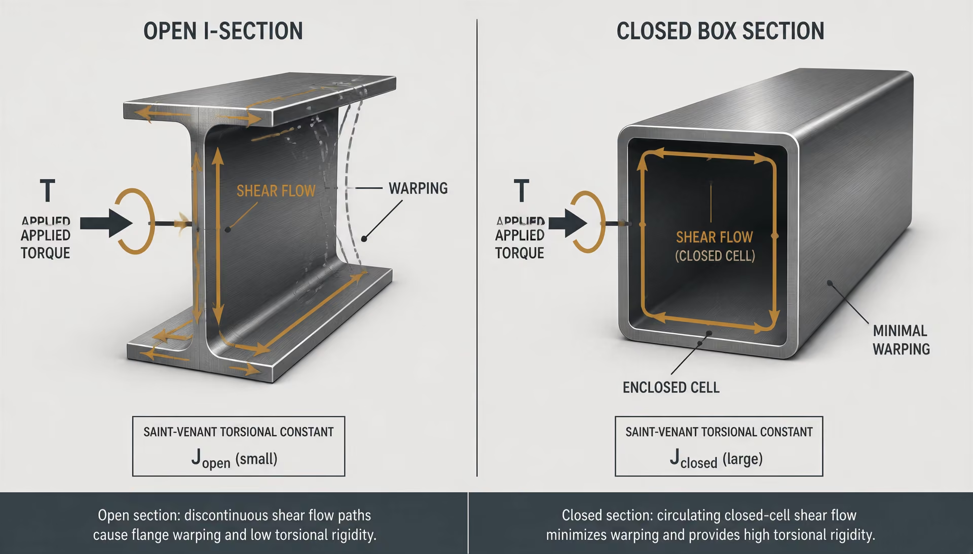
The torsional constant measures Saint-Venant torsional stiffness and is commonly reported in or . Thin-walled open sections such as I-beams and channels have relatively small , while closed box sections generally resist uniform torsion more effectively. The warping constant , often reported in or , describes resistance associated with nonuniform torsion and longitudinal warping. It matters particularly for open sections whose flanges can warp under torsional loading.
Shear area is another geometric quantity. It has area units, but it is not generally equal to . It represents the effective area used in shear-deformation or shear-resistance formulations, with values depending on the loading direction and section form. The plastic modulus or , also called the plastic section modulus, is found by locating the plastic neutral axis and summing first moments of the yielded areas. It is distinct from the elastic modulus : relates to first yield at an extreme fiber, whereas relates to a fully yielded idealized cross-section.
The Missouri S&T MDSolids resource lists centroidal location, second moments, section modulus, radius of gyration, plastic modulus, polar moment, and principal moments as separate outputs for generic and standard steel shapes. That separation is necessary.
Why the same section has multiple governing properties
A member does not have one universal “capacity property” because different actions create different stress and deformation patterns.
Axial tension is primarily related to area and the applicable net-area or connection provisions. Axial compression depends on area, material yield strength, unbraced length, effective length, and the smaller relevant radius of gyration. Flexure uses , , or , alongside lateral restraint, local slenderness, and grade strength. Shear depends on shear area and the web or plate elements that carry the shear. Torsion may depend on , , warping restraint, and load introduction. No single value can replace those checks.
This is why ANSI/AISC 360-16 defines and uses , , , , , and as different section-property quantities. AISC Part 1, Dimensions and Properties, is the reference portion of the 2023 Steel Construction Manual for tabulated dimensions and geometric properties, and the AISC Shapes Database v16.0 provides those data in U.S. customary and metric units. The Steel Construction Institute’s 2024 Blue Book likewise reports area, second moments, elastic and plastic moduli, radii of gyration, torsional constants, and warping constants for European sections.
The reference must match the profile and edition. EVS-EN 10365:2026 specifies nominal dimensions and masses for hot-rolled channels, I sections, and H sections; it does not replace a sectional-property table. The Blue Book supplies calculated geometric properties. ArcelorMittal notes that European calculated properties are generally reported in centimetres, while surface area and warping constant use metre- and decimetre-based units respectively. A unit conversion error can overwhelm a correct formula.
Tabulated values should be checked against a hand calculation or section-property program, especially for built-up, perforated, tapered, or composite shapes. Rounding can affect borderline results, and software axis labels can reverse major and minor properties. The correct question is therefore not “What is the section’s strength?” It is: which geometric property corresponds to the action, which axis and units apply, and which material and design standard supply the resistance rules?

The Coordinate System, Centroid, and Reference Axes
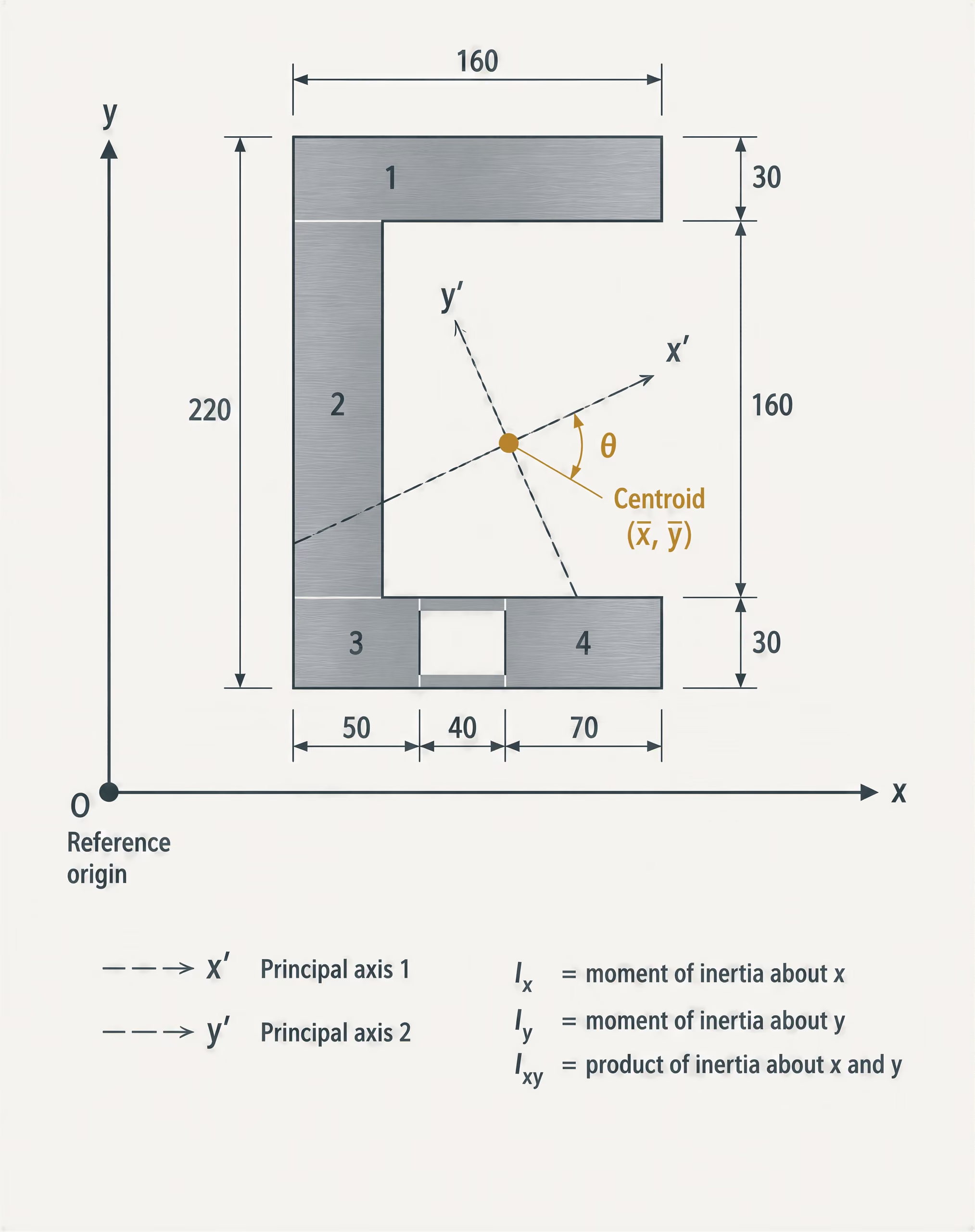
A section property has no complete meaning until its reference axis is stated. “The moment of inertia of an I-section” is incomplete: the value may refer to , , a principal moment, or a software quantity such as . The same cross-section can have a large second moment about one axis and a much smaller value about another. Coordinates must therefore be fixed before dimensions are combined or tabulated values are copied into a design calculation.
For a planar cross-section, take two perpendicular coordinates, commonly and , in the plane of the shape. A point in the area has coordinates , and an infinitesimal area is . The gross area is
The first moments of area locate the centroid:
\[ \bar{x}=\frac{1}{A}\int_A x\,dA,\qquad \bar{y}=\frac{1}{A}\int_A y\,dA. \]
These equations say that the centroid is an area-weighted average of all coordinates. A larger component contributes more strongly than a smaller component at the same distance. They also show why a centroid is not generally the geometric centre of the enclosing rectangle. A channel, angle, tee, or unsymmetrical built-up section can have its centroid substantially displaced from the apparent middle of its overall depth and width.
Centroidal coordinates
Once is known, define centroidal coordinates
\[ x'=x-\bar{x},\qquad y'=y-\bar{y}. \]
The centroidal axes pass through the centroid, so their first moments vanish:
\[ \int_A x'\,dA=0,\qquad \int_A y'\,dA=0. \]
This translation is not cosmetic. The centroidal second moments are
\[ I_x=\int_A y'^2\,dA,\qquad I_y=\int_A x'^2\,dA, \]
and the product of inertia is
The subscript convention used here follows common U.S. structural-engineering notation: measures squared distance from the -axis, and measures squared distance from the -axis. Thus is calculated with , not . This distinction is a frequent source of swapped values in spreadsheets.
Built-up-section calculation sequence
- 1. Define axes Set the origin, positive directions, and reference units.
- 2. Divide the shape Represent plates and voids as signed component areas.
- 3. Find the centroid Sum component areas and first moments.
- 4. Transfer inertia Apply the parallel-axis theorem to the common centroidal axes.
- 5. Check symmetry Confirm expected centroid and product-of-inertia results.
For a built-up section, calculate each component area and centroid first, then combine them. The University of Michigan’s area-property recitation presents this component method with first moments and the parallel-axis theorem. For example,
where is the component’s own centroidal value and is the vertical distance from its centroid to the assembled centroidal -axis. The corresponding expression applies about . Holes are treated as negative areas. A rectangle, triangle, circle, or hollow circle can therefore be calculated directly and then assembled into a more complicated steel section.
The units expose the type of quantity. Area has units of length squared, while , , and have units of length to the fourth power. A section modulus has units of length cubed, and a radius of gyration has units of length:
\[ r_x=\sqrt{\frac{I_x}{A}},\qquad r_y=\sqrt{\frac{I_y}{A}}. \]
These are not alternate names for inertia. They answer different questions and cannot be exchanged merely because they describe the same profile.
Abaqus uses a related but not identical label system. Its beam-section documentation defines centroidal properties by integrating squared coordinate distances for and , while integrates the product of coordinate distances. The numerical result can correspond to a familiar , , or only after the Abaqus local 1–2 axes have been mapped onto the engineering – axes. Never assume that the number after the letter is a U.S. axis name. Check the software’s local-axis definition and sign convention.
Major and minor axes
The major axis is the centroidal axis associated with the larger principal second moment of area; the minor axis has the smaller principal value. For a doubly symmetric I-section aligned with its web and flanges, these axes normally coincide with the geometric horizontal and vertical centroidal axes. If the section is deep relative to its flange width, the axis associated with bending about the strong direction has the larger inertia. Terminology must still be tied to the stated axis, because “strong axis” can be misread when a drawing is rotated.
The distinction has direct design consequences. Elastic bending stress uses a section modulus based on the selected axis,
\[ S_x=\frac{I_x}{c_x},\qquad S_y=\frac{I_y}{c_y}, \]
where is the greatest distance from that axis to the relevant extreme fibre. Buckling calculations use the corresponding radius of gyration. A tabulated cannot be substituted for simply because both are listed beside the same steel shape.[1] AISC Shapes Database v16.0. American Institute of Steel Construction. AISC Shapes Database, 2023.
The American Institute of Steel Construction lists these quantities in Part 1 of the Steel Construction Manual and in the AISC Shapes Database v16.0. The 2023 AISC description states that the database provides dimensions and section properties in U.S. customary and metric units. ANSI/AISC 360-16 defines quantities including , , , , , and . Those references identify the values, but the engineer must still confirm the profile designation, edition, units, and axis orientation.
European tables use their own presentation conventions. The Steel Construction Institute’s 2024 Blue Book lists area, second moments, section moduli, radii of gyration, torsional constants, and warping constants. EVS-EN 10365:2026 specifies nominal dimensions and masses for hot-rolled channels, I sections, and H sections; it is not itself a substitute for a sectional-property table. ArcelorMittal reports that European calculated properties are generally expressed using centimetres, with surface area and warping constant using metre- and decimetre-based units respectively. A unit conversion must be made before comparing those values with an AISC table.
Symmetry and principal axes
A centroidal product of inertia is zero about an axis of symmetry. Strong evidence
Symmetry provides a powerful check. If an area is symmetric about the -axis, every element at has a matching element at , so the paired contributions to cancel. Therefore about that axis. The same result follows for symmetry about the -axis. A section with two perpendicular symmetry axes has zero product of inertia about both centroidal axes.
Principal axes Centroidal axes obtained by rotation so that the product of inertia vanishes and bending properties are uncoupled.
An unsymmetrical section does not generally have this convenience. Its centroidal and axes may produce a nonzero , meaning bending about one axis can be coupled geometrically with bending about the other. The principal axes are the rotated centroidal axes for which the product of inertia is zero. The principal second moments are
and the principal-axis angle satisfies
subject to the adopted sign convention. The larger value is the major principal moment and the smaller is the minor principal moment.
For angles, channels, eccentric plates, and irregular built-up sections, principal-axis calculations may be necessary rather than optional. MDSolids, for example, reports centroidal location, second moments, principal moments, and related properties for generic and standard shapes. Software output remains a check, not a reason to ignore coordinates. Confirm the centroid, reproduce one simple component calculation, inspect the axis rotation, and identify whether the reported uses the same sign convention as the hand calculation. Geometry determines these properties; changing a designation from ASTM A36 to ASTM A572 Grade 50 changes material resistance, not the centroid or principal axes of an unchanged shape.
Area and First Moments of Area
Gross cross-sectional area
Cross-sectional area is a geometric quantity. It describes how much plane area is occupied by the section, not how strong the steel is. For a continuous shape,
where is an infinitesimal element of the cross-section. For a section divided into simple parts, the same quantity is calculated by addition:
For a rectangle, ; for a triangle, ; for a circle, ; and for a hollow circle,
with as the outside diameter and as the inside diameter. These formulas are integrations already performed for familiar shapes.
A hole is assigned a negative area. Thus, a rectangular plate containing a circular opening has
if the plate dimensions describe the material boundary before the opening is removed. The negative-area convention is not a shortcut with different mathematics; it is the signed form of subtracting the region from the integral.
The term gross area requires care. In section-property tables, it commonly means the full nominal cross-sectional area of the steel shape, including material later excluded by a hole, slot, cope, or other connection detail. A net area may remove holes according to a design rule, while an effective area may further account for local buckling, shear lag, or another provision. Those later design areas are not interchangeable with the geometric gross area. ANSI/AISC 360-16 uses distinct section-property and design provisions, and the applicable net or effective-area definition must be taken from the relevant limit-state calculation.
Dimensions, tolerances, and rounding affect the result. A nominal H-section dimension from a standard is not necessarily the exact measured dimension of every rolled member. EVS-EN 10365:2026 specifies nominal dimensions and masses for hot-rolled channels, I sections, and H sections; it does not replace a sectional-property table. The Steel Construction Institute’s Blue Book, by contrast, provides calculated properties such as area and second moments for European sections. The AISC Shapes Database v16.0, issued by the American Institute of Steel Construction in 2023, provides dimensions and section properties in U.S. customary and metric units.
Steel grade does not change this geometry. A section designated ASTM A992 W-shape and a geometrically identical section described with another grade designation have the same calculated area. Grade affects resistance, yield strength, and design checks—not the integral of . The same separation applies to European designations written under the applicable product and material standards.
First moments and centroid location
The first moment of area about an axis is the area integral of the coordinate multiplied by differential area:
\[ Q_x=\int_A y\,dA,\qquad Q_y=\int_A x\,dA \]
Here, is measured from the -axis and from the -axis. has units of length cubed, such as or . It is not the second moment , whose units are length to the fourth power.
The centroid coordinates follow directly:
This is the component-area method taught in the University of Michigan’s section-property recitation. Each component contributes its area multiplied by the coordinate of its own centroid. A large area far from the reference axis has more influence than a small area close to it.
Choose axes and signs before calculating. A common convention takes rightward and upward as positive. A component below the -axis then has negative , producing a negative contribution to . A hole has negative , so its first-moment contribution is also negative when its coordinate is positive. If the reference origin is changed, individual moments change, but the final centroid does not.
For a symmetric section, the centroid lies on every axis of symmetry. A doubly symmetric I-section therefore has its centroid at the intersection of its web and flange symmetry axes. Symmetry is a useful check, not a reason to omit the calculation when a plate, opening, weld attachment, or eccentric stiffener breaks it.
The same notation appears in transverse-shear formulas, but the selected area and axis must be stated. For a beam,
where is the first moment of the portion of area on one side of the point where shear stress is evaluated, about the neutral axis; is the second moment of the whole section about that axis; and is the local width or thickness resisting the shear flow. This is not automatically the first moment of the entire cross-section about an arbitrary datum. About its centroidal axis, the first moment of the complete area is zero.
Component-area tables for built-up sections
A table makes a decomposed-section calculation auditable. At minimum, include each component’s signed area, centroid coordinates, and first-moment contributions:
| Component | |||||
|---|---|---|---|---|---|
| Top plate | |||||
| Web | |||||
| Bottom plate | |||||
| Opening |
Then calculate
\[ \bar{x}=\frac{\sum A_i x_i}{\sum A_i},\qquad \bar{y}=\frac{\sum A_i y_i}{\sum A_i} \]
The table should use one coordinate system and one unit system throughout. Mixing millimetres with metres can introduce factors of in first moments and in second moments.
For a built-up section, the table establishes the centroid before the parallel-axis theorem is applied to and . It also provides a direct check: the algebraic first moment of the complete area about the calculated centroid must be zero. Software such as Missouri S&T’s MDSolids can calculate centroidal location and related properties for generic and standard steel shapes, but an independent component table remains an effective verification.
Tabulated values must match the exact profile, axis convention, edition, and units. AISC Part 1 is the reference section of the Steel Construction Manual for standard U.S. dimensions and geometric properties. European tables may report calculated properties in centimetres; ArcelorMittal states that surface area and warping constant use metre- and decimetre-based units, respectively. Area and first moments therefore need unit labels, not bare numbers.
Second Moments of Area: , , and
Second moments of area describe how a cross-sectional area is distributed about specified axes. They are geometric properties, not material-strength values. Changing structural steel from ASTM A36 to ASTM A572 Grade 50 changes the resistance checks and design strengths, but it does not change , , or when the profile dimensions remain the same.
The axis labels must be read carefully. In the common convention, measures area distribution about the -axis, so the squared distance is the -coordinate. Likewise, measures distribution about the -axis and uses the squared -coordinate. Some software and standards use numbered axes such as and , so the coordinate convention must be checked before comparing values. Abaqus documentation defines centroidal properties by integrating squared coordinate distances for and , and the product of coordinate distances for (Abaqus, 2024).
Integral definitions
For a cross-sectional area , with coordinates measured from the selected origin,
and
The first two quantities are second moments of area. Their units are length to the fourth power: , , or . The product of inertia has the same units.
The squared distance is the central point. A small area element at distance from the -axis contributes , not merely . If one element is twice as far from the axis as another element of equal area, it contributes four times as much to . Material near the neutral axis contributes little; material placed far away contributes much more. This is why the flanges of an I section make a large contribution to strong-axis bending stiffness, while the web contributes a larger share of the weak-axis property than its area alone might suggest.
For a rectangle of width parallel to the -axis and depth parallel to the -axis, with centroidal axes through its middle,
\[ I_x=\frac{bh^3}{12}, \qquad I_y=\frac{hb^3}{12}. \]
The cubic dimension explains why rotating a rectangular section can change bending stiffness substantially. A deep rectangle has a much greater than a deep rectangle of the same width, even though its area is only doubled.
For a triangle, the centroidal second moment parallel to its base is
where is the base and is the perpendicular height. A circle of radius has
about any centroidal diameter. For a hollow circle, the outer and inner contributions are subtracted:
These formulas are useful checks against section-property software and tables; they are not interchangeable with the polar moment, torsional constant, or section modulus.
The parallel-axis theorem
Hand calculations for a compound section begin by dividing the shape into simple components. For each component, determine its area , centroid coordinates , and centroidal second moments and . First moments locate the overall centroid:
\[ \bar{x}=\frac{\sum A_i x_i}{\sum A_i}, \qquad \bar{y}=\frac{\sum A_i y_i}{\sum A_i}. \]
Once the compound centroid is known, the parallel-axis theorem transfers each component property to the compound axes:
For the product of inertia,
The transfer terms are often more important than the component centroidal values. A flange may have modest own-axis inertia, but its distance from the overall centroid can produce a large contribution.
Consider a symmetric T section made from a flange and a web, with the web centered beneath the flange. The flange area is , and the web area is . Measuring upward from the bottom of the web, their centroids are at and . Therefore,
For the flange,
and for the web,
The transferred property is approximately
giving
The web’s own depth produces much of the result, while the flange’s offset still adds a substantial term. Omitting the parallel-axis terms would understate the section property.
For a void, the same method applies with negative area and negative component properties. This is how a rectangular hollow section can be calculated from an outer rectangle minus an inner rectangle, provided the inner dimensions and axis locations are defined correctly.
Product of inertia and rotated axes
The product of inertia records whether area lies in paired positive or negative coordinate regions. With centroidal coordinates, an area element in the first quadrant has positive ; one in the second quadrant has negative . Opposing contributions can cancel.
vanishes when the section has a symmetry axis coincident with either the - or -axis, provided the origin is at the centroid. Reflection across the -axis changes to , reversing the sign of , so symmetric pairs cancel. The same argument applies to symmetry about the -axis. Rectangles, circles, I sections, and centered hollow sections therefore have about their usual centroidal symmetry axes.
An angle section, channel, tee, or unsymmetrical built-up section generally has only one symmetry axis or none. Its product of inertia may not vanish about arbitrary centroidal axes. Even a section with one symmetry axis has only when one selected axis lies along that symmetry axis and the other is perpendicular to it.
Rotating the axes changes the three quantities according to
The signs depend on the adopted axis and rotation convention; the convention must remain consistent throughout a calculation. Principal axes are orientations for which . The corresponding principal moments are
For a doubly symmetric I section, the familiar strong and weak axes are already principal axes. For a channel or angle, centroidal geometric axes may not be principal, and bending about one axis can produce curvature or stress effects associated with the other. Unsymmetrical built-up sections require the same treatment; assuming without checking symmetry can give the wrong bending response.
AISC Shapes Database v16.0, issued by the American Institute of Steel Construction in 2023, provides dimensions and properties in U.S. customary and metric units, while AISC Part 1 supplies tabulated dimensions and geometric properties. The Steel Construction Institute’s 2024 Blue Book gives European section properties, including second moments and principal-axis information where applicable. EVS-EN 10365:2026 specifies nominal dimensions and masses, not every calculated property. Unit conventions also differ: ArcelorMittal states that European calculated properties are generally reported in centimetres, with surface area and warping constant using metre- and decimetre-based units. A value copied from a table is useful only after confirming the exact profile, axis, units, and standard edition.
Hand Calculations for Basic Geometries
Hand calculation starts with a boundary and a coordinate system, not with a steel grade. Let and locate points in the cross-section, and let the origin initially be any convenient reference point. The gross area is
The centroid follows from the first moments:
\[ \bar{x}=\frac{1}{A}\int_A x\,dA,\qquad \bar{y}=\frac{1}{A}\int_A y\,dA \]
Once the centroid is known, centroidal second moments of area are
\[ I_x=\int_A (y-\bar{y})^2dA,\qquad I_y=\int_A (x-\bar{x})^2dA \]
and the product of inertia is
This agrees with the Abaqus convention: I11 and I22 integrate squared coordinate distances, while I12 integrates the product of coordinate distances. The subscript labels may change between references, so the axis definition must be read before using a table.
Rectangular and triangular sections
For a rectangle of width measured parallel to the -axis and depth measured parallel to the -axis,
If the rectangle is centered about both axes, its centroid is at its geometric center, and symmetry gives . The centroidal second moments are
\[ I_x=\frac{bh^3}{12},\qquad I_y=\frac{hb^3}{12} \]
The dimensions do not enter in the same way. Increasing increases with the third power, whereas increasing increases it only linearly. The opposite applies to . This is why placing material farther from the axis can have a much greater effect on bending stiffness than adding the same area near that axis.
For a rectangle whose lower edge is used as the reference axis, the centroid lies at
The second moment about that edge is
The centroidal result follows from the parallel-axis theorem:
Confusing these two values is a common hand-calculation error.
For a triangle, let be the base and the perpendicular height. Its area is
The centroid lies one-third of the height from the base, or two-thirds of the height from the apex. For an axis parallel to the base through the centroid,
About the base itself,
Again, the parallel-axis theorem connects the two values. The centroidal depends on the triangle’s horizontal geometry. For an isosceles triangle with its symmetry axis vertical,
and symmetry requires about the centroidal horizontal and vertical axes. A scalene triangle generally has a nonzero product of inertia in those axes, so its principal axes are rotated.
A dimensional check catches many errors immediately. Area has units , first moment has units , and second moment has units . Thus is dimensionally suitable for a second moment, while is not. If every length is changed by a scale factor , area changes by , centroid coordinates by , and second moments by .
Circular and hollow-circular sections
For a solid circle of radius , or diameter ,
Every centroidal diameter is a symmetry axis. Therefore,
and
The polar second moment about the centroid is
This polar quantity is not automatically the Saint-Venant torsional constant used for beam torsion in every cross-section. For a circular section, the solid-circle torsional constant equals the polar second moment, but that equivalence should not be transferred to open I-shaped or channel sections.
For a hollow circle with outside radius and inside radius ,
The centroid remains at the common center, and
The polar second moment is
The same equations can be written with outside and inside diameters and :
\[ A=\frac{\pi}{4}(d_o^2-d_i^2),\qquad I_x=I_y=\frac{\pi}{64}(d_o^4-d_i^4) \]
The subtraction is geometric removal of the void, not an approximation to a solid section. It also provides useful limiting checks. If , the hollow-circle equations reduce to the solid-circle equations. If approaches , the area and second moments approach zero. A thin wall can retain a meaningful enclosed area while its bending and torsional properties depend strongly on wall thickness, so replacing it with a solid circle of the same outside diameter is unacceptable.
Combining simple shapes into steel profiles
Built-up sections are calculated by adding material and subtracting voids. Divide the profile into rectangles, triangles, circles, or other shapes whose properties are known. For each component , record its signed area , centroid coordinates , and centroidal properties , , and . Use negative area for a cutout.
The composite centroid is
\[ \bar{x}=\frac{\sum A_i x_i}{\sum A_i},\qquad \bar{y}=\frac{\sum A_i y_i}{\sum A_i} \]
Then apply the parallel-axis theorem:
A void contributes negatively to every area-based term. For example, a rectangular tube can be treated as an outside rectangle minus an inside rectangle, provided both rectangles share the correct reference axes. An I-section can be assembled from a web rectangle and two flange rectangles, with offsets from the overall centroid included through the parallel-axis terms. A channel can be assembled similarly, but its centroid is not generally on both geometric axes.
Symmetry is a powerful check. A section symmetric about the -axis must have when that axis is used as the reference, and its centroidal is zero. A doubly symmetric I-section has principal axes coincident with its centroidal axes. If a calculation produces a nonzero product of inertia for such a section, the component coordinates, signs, or axis labels are wrong.
The final values should also pass limiting checks: removing a component must reduce area; moving material farther from an axis should increase the corresponding second moment; and a void approaching zero size should have no effect. Keep dimensions in one unit system throughout. With lengths in millimetres, is in and in ; converting the result to metres requires division by for area and for second moment. European tables commonly report calculated properties in centimetres, while surface area and warping constant use metre- and decimetre-based units, as ArcelorMittal explains.
Hand results are checks against, not replacements for, the exact profile table. AISC Shapes Database v16.0 and AISC Part 1 provide U.S. shape dimensions and geometric properties; SCI P363, The Blue Book, provides European sectional properties. EVS-EN 10365:2026 specifies nominal dimensions and masses, not every derived property. Plate thickness tolerances, fillets, corner radii, and rounding can change the result. Confirm the exact designation and edition before comparing a hand-built idealization with a published steel profile.
Section Modulus, Radius of Gyration, and Polar Properties
Section modulus, radius of gyration, and polar properties are derived from the same cross-sectional geometry, but they answer different engineering questions. None is a material-strength value. Changing from ASTM A36 steel to ASTM A992 steel does not change , , , or when the physical section dimensions remain the same; the grade changes resistance, stiffness checks through the material modulus where relevant, and allowable or design strengths. The geometry still comes from the shape.
Axis labels must be read before any number is copied from a table. AISC, SCI, and European tables do not replace that check. The American Institute of Steel Construction states that AISC Shapes Database v16.0 provides dimensions and section properties in U.S. customary and metric units, while AISC Part 1 is the reference section for tabulated dimensions and geometric properties. In Europe, EVS-EN 10365:2026 specifies nominal dimensions and masses for hot-rolled channels, I sections, and H sections; calculated properties are then supplied by references such as the Steel Construction Institute’s Blue Book.
Elastic section modulus
The elastic section modulus is the relevant centroidal second moment divided by the distance from that centroidal axis to the extreme fiber. For bending about the -axis,
where is the greatest distance from the -axis to the tension or compression extreme fiber. For bending about the -axis,
where is the greatest distance from the -axis to the extreme fiber. The subscript on identifies the bending axis, not the direction of the extreme-fiber distance in the numerator.
This distinction matters for an unequal-flange I section, channel, angle, or other unsymmetrical shape. The distances to the two extreme fibers may differ, so the section can have separate positive and negative elastic moduli. A table may list and , or and , rather than one value. Using the larger value for both faces can produce an unsafe bending resistance if the smaller value governs.
The units follow directly from the equation. and have dimensions of length to the fourth power, and has dimensions of length, so and have dimensions of length cubed. Typical systems report , , or . A conversion error between and introduces a factor of 1,000, not 100.
For a rectangular section of width and depth ,
\[ I_x=\frac{bh^3}{12},\qquad S_x=\frac{bh^2}{6}. \]
The depth is cubed in and squared in , which explains why rotating a rectangular bar can change bending resistance sharply. The same area rotated by 90 degrees is not the same bending section.
Elastic section modulus applies to the elastic stress distribution, where bending stress varies linearly from zero at the neutral axis to its maximum at the extreme fiber:
It should not be confused with the plastic section modulus , which is based on equal tensile and compressive resultant forces after the entire cross-section has reached yield. is also a length-cubed property, but it is not interchangeable with .
Radius of gyration
The radius of gyration describes how far area is distributed from a specified centroidal axis in an equivalent mathematical sense. About the -axis,
and about the -axis,
Here is the gross cross-sectional area. Since has units of and has units of , each radius of gyration has units of length: millimetres, centimetres, or inches.
A larger means that more area is distributed away from the relevant axis. That is why an I section can have a large but a much smaller : its flanges place substantial area far from the strong axis, while the web and flange thicknesses leave less area distributed about the weak axis.
The primary design use is axial-member buckling. For a member length and effective-length factor , the slenderness ratio about each axis is
\[ \frac{KL_x}{r_x} \quad\text{and}\quad \frac{KL_y}{r_y}. \]
The larger value usually identifies the more critical buckling direction, subject to end restraint, bracing, torsional-flexural effects, and the design standard’s classification rules. An area-only comparison misses this behavior. Two sections may have the same gross area and similar mass, yet very different weak-axis radii and therefore different compression performance.
The radius of gyration is not a radius visible on the steel profile. It is calculated from area distribution. Missouri S&T’s MDSolids resource lists centroidal location, second moments, section modulus, radius of gyration, plastic modulus, polar moment, and principal moments as separate outputs, a useful reminder that these labels describe different calculations.
For built-up sections, , centroid coordinates, component second moments, and the parallel-axis theorem are used before taking the square root. The result should be checked against the axis convention. Abaqus describes centroidal properties through area integration: and integrate squared coordinate distances, while integrates the product of coordinate distances. This is the same geometric foundation used in hand calculations, though software may label axes differently from a steel table.
Polar moment and its limits
The polar moment of area about a point perpendicular to the section plane is
For perpendicular centroidal - and -axes,
It has units of , such as or . For a solid circular area of radius ,
and for a circular annulus with outer radius and inner radius ,
These expressions make the polar moment useful in circular-shaft torsion and in problems where the geometry and loading are rotationally symmetric. For a circular shaft under elastic torsion, the polar moment is commonly written , and the familiar relation is
That notation creates a frequent error: polar moment is not automatically the torsional constant for every steel section.
The Saint-Venant torsional constant describes resistance to uniform torsion and depends on the cross-section’s warping and shear-flow behavior. For a solid or thin-walled circular section, . For a general open section, they are different quantities. A thin rectangular strip with breadth and thickness , where is much larger than , has an approximate torsional constant of order , whereas its contribution to can be governed by the squared distance of the strip from the centroid. An open I section can therefore have a polar moment that looks substantial while possessing a comparatively small Saint-Venant torsional constant.
Closed box sections generally have much greater torsional efficiency than open sections because circulating shear flow can develop around the enclosed cell. If torsional restraint causes longitudinal warping, alone is insufficient; the warping constant , with dimensions of , enters the analysis. ANSI/AISC 360-16 defines and uses , , , , , and as separate section-property quantities. The Blue Book likewise lists elastic and plastic moduli, radii, torsional constants, and warping constants separately.
Unit conventions require particular care in European references. ArcelorMittal notes that calculated section properties are generally reported in centimetres, while surface area and warping constant use metre- and decimetre-based units respectively. A value copied from a Blue Book or manufacturer table must therefore be identified by property and unit, not merely by its numerical size. Before using any tabulated , , , or , verify the exact profile designation, axis convention, standard edition, and whether the value represents a gross, nominal, or otherwise specified geometry.
Elastic and Plastic Section Properties
Elastic neutral axis and extreme fibers
Elastic section properties describe the stress distribution before yielding. For a prismatic, homogeneous steel section under a bending moment about a centroidal axis, the elastic neutral axis passes through the centroid. Fibers on one side of that axis are in compression and fibers on the other side are in tension; at the neutral axis, the longitudinal bending stress is zero. The distribution is linear:
where is the applied moment, is the distance from the neutral axis, and is the relevant centroidal second moment of area.
The elastic section modulus is therefore
where is the distance from the neutral axis to the extreme fiber being checked. A section with unequal distances above and below its centroid has two elastic section moduli, such as and . They are not interchangeable. Under sagging and hogging moment, different extreme fibers may govern because differs.
This distinction matters for a channel, angle, tee, or unsymmetrical built-up section. The centroidal axis still defines the elastic neutral axis for a homogeneous section, but the farthest fiber may be much farther from that axis on one side. A single value copied from a table can conceal that asymmetry. Doubly symmetric I and H sections commonly have equal positive and negative elastic moduli about the major axis, while singly symmetric sections generally do not.
The geometric basis is the second moment of area. Abaqus documentation describes and as integrations of squared coordinate distances over the cross-sectional area, while integrates the product of coordinate distances (Abaqus, 2024). That definition explains why moving a flange area farther from the centroid can increase substantially without adding much steel. It also explains why is a geometry quantity, not a grade-dependent strength value.
Elastic section modulus has units of length cubed: , , or . It must not be confused with the radius of gyration, which has units of length, or with the plastic modulus, which also has units of length cubed but is calculated differently.
Plastic neutral axis and plastic modulus
The plastic neutral axis (PNA) is established from a fully yielded stress pattern rather than from a linear elastic one. For a homogeneous steel section in pure bending, the PNA divides the cross-sectional area into equal compression and tension areas:
The stress is idealized as the yield stress in compression on one side and the yield stress in tension on the other. The resultant axial force is therefore balanced. For a section with variable material strengths or composite materials, equal geometric areas are not generally sufficient; the compression and tension resultants must balance using the applicable material stresses.
The plastic modulus, commonly written , is the first moment of the yielded areas about the PNA:
\[ Z=\int_A |y-y_p|\,dA \]
For component areas, it can be calculated by summing each area multiplied by the distance from its centroid to the PNA. The corresponding fully plastic moment is often written
for a uniform steel grade, but is a resistance expression, not a geometry-only identity. Changing from ASTM A992 to ASTM A36 changes the specified yield strength used in a design check; it does not change the geometric calculated from the same dimensions. The same separation applies to European designations such as S275 and S355 under the relevant product and design standards.
The elastic modulus and plastic modulus answer different questions. relates the moment to the first yield at the extreme fiber under an elastic stress distribution. relates the moment to a fully yielded cross-section with balanced compression and tension blocks. Their ratio,
is the shape factor for the specified bending axis and governing extreme fiber. It indicates the additional moment capacity associated with plastic stress redistribution, but it does not certify that the member may reach or sustain that capacity.
A large plastic modulus alone cannot classify a cross-section as compact. Noncompact, compact, and slender classifications depend primarily on plate-element width-to-thickness ratios, boundary conditions, stress gradients, and the limiting provisions of the governing design standard. A slender web can contribute substantially to a calculated , yet local buckling may occur before the full plastic stress pattern develops. Conversely, a compact section can possess a modest shape factor. Classification is a stability and ductility judgment, not a ranking based on one tabulated number.
When tabulated values differ
Two credible tables can show slightly different elastic or plastic properties for what appears to be the same section. The first question is whether the profile designation and edition are identical. The American Institute of Steel Construction states that AISC Shapes Database v16.0, published in 2023, provides dimensions and properties in U.S. customary and metric units, while Part 1 of the 16th Edition Steel Construction Manual is the reference section for standard-shape dimensions and geometric properties. A W-shape listed there should not be compared casually with a nominally similar European HE section.
The Blue Book, maintained by the Steel Construction Institute and referenced here in its 2024 form, reports area, second moments of area, elastic and plastic section moduli, radii of gyration, torsional constants, and warping constants. EVS-EN 10365:2026 specifies nominal dimensions and masses for hot-rolled channels, I sections, and H sections; it is not itself a substitute for every calculated sectional-property table. The distinction is important. A nominal flange thickness in a product standard, a modeled thickness in a manufacturer table, and a rounded dimension in a design database may produce slightly different results.
Profile geometry also includes details that a simplified hand sketch may omit: flange and web fillets, root radii, taper, corner radii, and rolling tolerances. A rectangle-based approximation can reproduce the broad behavior of an I-section while missing the exact area, centroid, , , or . Rounding then adds another difference. A table may display , while software retains more digits internally.
Units cause avoidable errors. ArcelorMittal notes in 2024 that European calculated properties are generally reported in centimetres; surface area uses metre-based units and the warping constant uses decimetre-based units. Thus in and in cannot be copied into an inch-pound calculation without conversion.
MDSolids from Missouri S&T lists centroidal location, second moments, section moduli, radii of gyration, plastic modulus, polar moment, and principal moments for generic and standard steel shapes (2024). It is useful for checking a hand calculation, but agreement with a plastic modulus does not prove that a section meets a compactness limit or a design resistance. Confirm the axis convention, gross or net basis, fillet treatment, units, and source edition before accepting a tabulated value. Geometry establishes the property; the applicable design standard establishes how that property may be used.
Torsional Constant J and Warping Constant Cw
Saint-Venant torsion and J
The torsional constant, , measures a cross-section’s resistance to Saint-Venant torsion: twisting produced by a torque when the section is free to warp along its length. It is a geometric property, not a steel-strength value. In a simple elastic model, the torsional shear stress and twist are related through the material shear modulus , the applied torque , and :
where is the angle of twist per unit length. A larger means less twist for the same torque, provided the material, loading, and boundary conditions are otherwise identical. The dimensions of are length to the fourth power, such as , , or .
The phrase “torsional constant” does not mean “polar moment of inertia” in every section. The polar second moment of area is
about perpendicular centroidal axes. For a circular or annular section, , because the circular geometry permits the Saint-Venant stress function to produce that direct equivalence. For most noncircular sections, especially thin-walled open sections, \(J\ne I_p\). Treating the two quantities as interchangeable can produce a major error in predicted twist and torsional stress.
For a thin rectangular strip of length and thickness , where is much greater than , the Saint-Venant torsional constant is approximately
The thickness appears to the third power. That is why a thin flange or web contributes far less to Saint-Venant torsional stiffness than a circular calculation based only on its distance from the centroid might suggest. The polar moment records the distribution of area about an axis; records the section’s ability to develop a compatible shear-stress field during twist. Those are related geometric ideas, but they are not the same calculation.
ANSI/AISC 360-16 identifies as a section-property quantity used in steel design, alongside , , , , and . The AISC Shapes Database v16.0, published by the American Institute of Steel Construction in 2023, provides dimensions and section properties for standard shapes in U.S. customary and metric units. AISC Part 1, Dimensions and Properties, serves as the tabulated-property reference in the 16th Edition Steel Construction Manual. The listed value must match the exact W, S, M, HP, C, MC, WT, L, HSS, or other profile designation; a similar nominal depth is not enough.
Warping resistance and Cw
, the warping constant, describes resistance to longitudinal warping of a cross-section under nonuniform torsion. Its dimensions are length to the sixth power, commonly , , or . It should not be confused with , which describes the cross-section’s Saint-Venant response.
When a beam twists, different parts of an open section generally want to move longitudinally by different amounts. In an I-section, for example, the flanges can warp in opposite directions. If the ends are free and the applied torque is uniform, much of the response may be represented by Saint-Venant torsion through . If diaphragms, end plates, connections, floor systems, welds, or supports prevent that longitudinal movement, warping stresses develop. The resulting torsional response includes warping torsion, and becomes important.
The magnitude of that effect depends on restraint, not on the section label alone. A simply supported member with details that permit flange warping may have a modest warping contribution. The same section fixed into a rigid connection or tied to a stiff diaphragm can develop substantial bimoment and longitudinal normal stress. A calculation that inserts without defining the end conditions is incomplete.
For doubly symmetric I- and H-sections, the major-axis warping constant is often large because the separated flanges provide a long lever arm for opposing longitudinal warping. A simplified form for a thin-flange I-section is proportional to the flange area multiplied by the square of the distance between flange centroids:
with the precise expression depending on flange geometry, web thickness, and the chosen axis. This approximation explains why can be large even though remains comparatively small.
The AISC tables and the SCI Blue Book report for many standard sections. The Steel Construction Institute’s Blue Book, identified by SCI in 2024 as a source of European dimensions and sectional properties, includes area, second moments, elastic and plastic section moduli, radii of gyration, torsional constants, and warping constants. These are calculated geometric properties. EVS-EN 10365:2026 specifies nominal dimensions and masses for hot-rolled channels, I sections, and H sections; it is not a substitute for a sectional-property table.
Unit checking is particularly important for . ArcelorMittal’s 2024 explanatory notes state that European calculated properties are generally reported using centimetre-based conventions, while surface area uses metre-based units and warping constant uses decimetre-based units. A table may therefore show in and in . Converting only the force or length unit, while leaving the sixth-power quantity unchanged, can invalidate the result.

Open versus closed steel sections
| Section form | Typical torsional behavior | Important consideration |
|---|---|---|
| Open I-section | Often small J relative to Ip | Warping and load eccentricity |
| Channel | Open-section torsion | Shear center commonly outside the material |
| Angle | Unsymmetrical response | Principal axes and shear center may be offset |
| Closed tube | Generally greater Saint-Venant efficiency | Circulating shear flow around the cell |
Open I-sections, channels, tees, and angles have disconnected thin-walled paths around much of their perimeter. Their Saint-Venant torsional constant is therefore often small compared with their , , or polar moment. An I-section can be extremely stiff in major-axis bending yet twist readily when its load does not pass through the shear centre. A channel adds another complication: its shear centre lies outside the section, so a transverse load through the centroid can create torsion.
Angles and tees are also unsymmetric. Their centroid, principal axes, shear centre, and warping response do not coincide in the simple manner found in a doubly symmetric I-section. The product of inertia may be nonzero in the selected coordinate system, requiring principal-axis transformation before bending and torsion are assessed correctly.
Closed tubes behave differently because their walls form a continuous cell. Torque can be carried by circulating shear flow around the enclosed area. For a thin-walled single-cell closed section, the torsional constant is approximately
where is the area enclosed by the wall median line and the integral accounts for wall length and thickness. This mechanism usually gives a closed rectangular or circular HSS a much higher Saint-Venant torsional stiffness than an open section of similar mass. Closed sections still can warp near concentrated loads, discontinuities, and connections, but free uniform warping is often less dominant than it is in an open I-section.
These distinctions matter in analysis software as well as hand calculations. Abaqus defines centroidal properties by integrating squared coordinate distances for and , and coordinate products for ; that integration framework does not turn into . Missouri S&T’s MDSolids resource separately calculates polar moment and torsional properties for generic and standard shapes. A sound model therefore imports and from a matching standard or calculates them with a method suited to the section topology, then verifies units, axes, restraints, and connection details before applying the values to steel design.
Shear Area, Shear Center, and Unsymmetrical Sections
Effective shear areas
Gross area is the area used in axial-force calculations and in several geometric properties. It is not automatically the area that resists transverse shear. Shear area is a separate property, commonly written , , , or represented through a shear-correction factor. Its units are area, but its numerical value depends on the direction of shear and on the assumed distribution of shear stress over the section.
For a rectangular section carrying shear parallel to its depth, the shear stress is not constant. It is zero at the free top and bottom surfaces, rises toward the neutral axis, and reaches a maximum there. The average stress therefore does not equal the actual peak stress. A shear-area representation replaces the nonuniform stress field with an equivalent average relation, often written
Since the peak and average stresses differ, is not simply the gross area. For a solid rectangle of width and depth , the familiar elastic distribution gives a maximum shear stress of , so an equivalent area based on that maximum would be . Other definitions, including those used in beam finite elements, may produce a different effective area because they are tied to shear strain energy rather than only to the maximum stress.
Thin-walled I sections make the distinction more consequential. Under vertical shear, most of the force is carried by the web, while the flanges contribute comparatively little because their material lies far from the web’s shear-flow path and because flange shear stress varies across the flange width. Treating the full area as a uniform shear area can understate web shear stress. For horizontal shear, the flange arrangement becomes more important. A channel, angle, or tee has no pair of equal, opposing flanges to balance the shear flow, so the distribution must be calculated from the actual geometry.
The usual thin-walled relation,
expresses shear flow at a location from the first moment of the area outside that location, with taken about the relevant centroidal axis. It shows why flange and web stresses cannot be assigned by area fractions alone. The location of the material, represented by , matters. At junctions between web and flange, shear flow must also satisfy equilibrium and compatibility.
A calculated shear area should therefore be labeled by direction and definition. It should not be substituted for , , , or a section modulus. The Georgia Tech stainless-steel design guideline is useful in this respect because its computed section-property outputs separate area, centroidal inertias, section moduli, radii of gyration, torsional quantities, and shear-related quantities rather than presenting one number as a general measure of shape efficiency. The same geometric treatment applies to carbon and low-alloy structural steel. Changing a designation from ASTM A36 to ASTM A572 Grade 50, or from one stainless grade to another, changes resistance values and design limits, not the shear area calculated from unchanged dimensions.

Shear center location
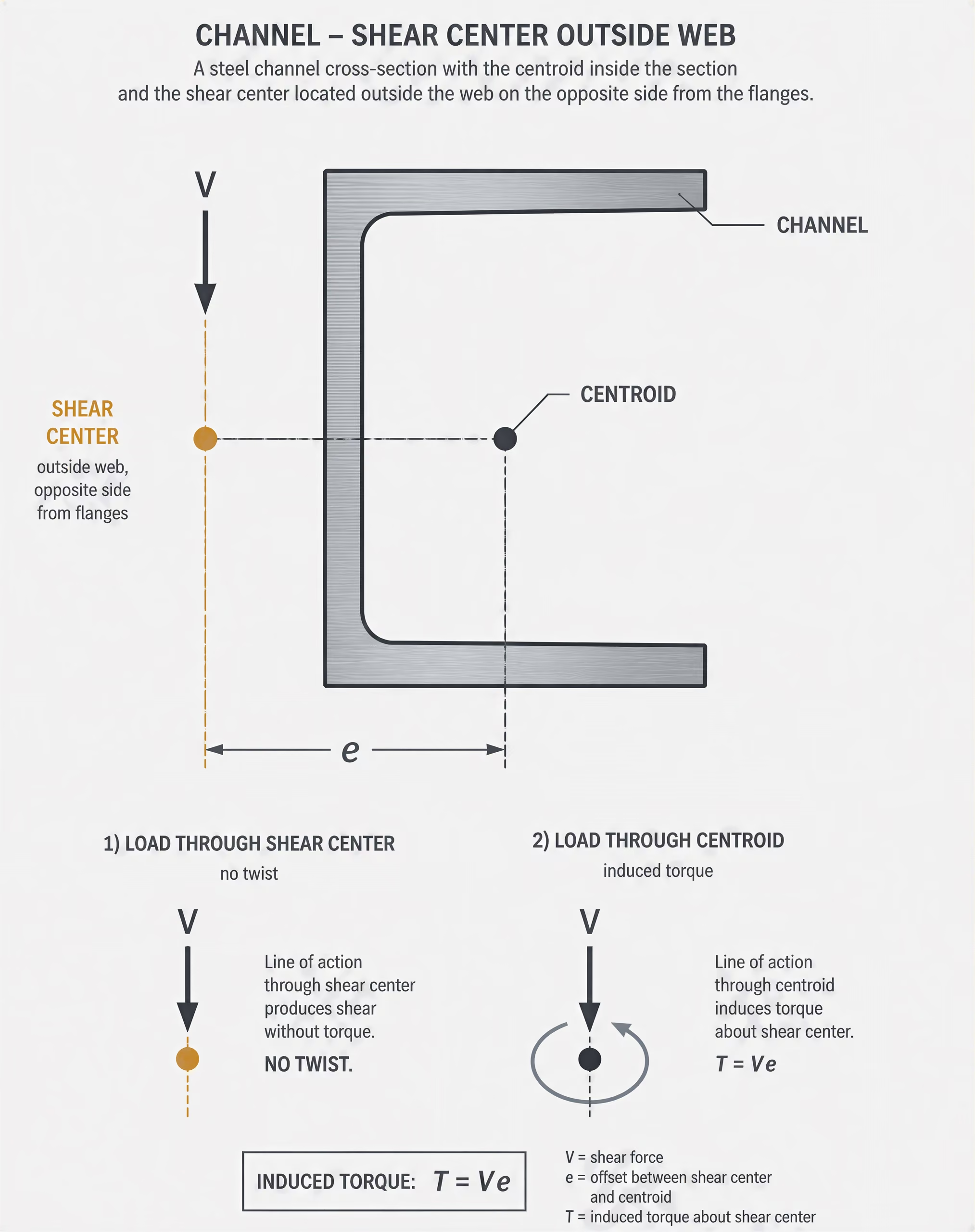
Shear center The load-line location at which a transverse force produces no additional torsional moment in the cross-section.
The shear center is the point in a cross-section through which a transverse load must act to produce bending without twisting. For a doubly symmetric I section, the shear center coincides with the centroid. For a section with only one axis of symmetry, it lies on that symmetry axis, but it need not coincide with the centroid. For a section with no symmetry, the shear center may be offset in both coordinate directions.
The reason is shear flow. A transverse force produces elemental shear forces distributed around the section. Their resultant equals the applied shear, but their combined line of action may not pass through the centroid. The offset creates a torque. Applying the load at the shear center supplies the correct line of action and removes that torque.
A channel is the standard warning example. Its flanges extend to one side of the web, so vertical shear generates unequal flange shear flows whose resultant generally acts away from the centroid. The shear center is commonly outside the material, on the opposite side of the web from the flanges. A load applied through the centroid can therefore cause simultaneous bending and twisting. An angle is more difficult still: with no symmetry axis in the usual equal-leg or unequal-leg cases, both the centroid and shear-center coordinates must be obtained from the complete section geometry. A tee has one axis of symmetry, which constrains the shear center to that axis, but the stem and flange still place it away from the centroid in many cases.
The calculation requires more than , , and . One must determine shear flow, integrate the moments of that flow about a reference point, and locate the point where the net torsional moment is zero. In thin-walled open sections, idealized wall thickness and junction geometry affect the result. Rounded corners, fillets, lips, and local welds may shift the answer, particularly when the section is small or the wall is thin.
Published tables must also be read with their axis conventions. The AISC Shapes Database v16.0, identified by the American Institute of Steel Construction in 2023 as providing dimensions and properties in U.S. customary and metric units, is tied to specific shape designations and axes. The Steel Construction Institute’s Blue Book similarly reports European sectional properties. EN 10365:2026 specifies nominal dimensions and masses for hot-rolled channels, I sections, and H sections; it does not replace a sectional-property table. The Blue Book supplies calculated properties, while ArcelorMittal notes that European calculated properties are generally reported in centimetres, with surface area and warping constant using metre- and decimetre-based units. A shear-center distance must be checked separately for units, axis origin, and sign.
Coupling between bending and torsion
In an unsymmetrical section, bending and torsion are coupled in two related ways. First, a load through the centroid may not pass through the shear center, creating a torsional moment
where is the perpendicular distance between the load line and shear-center line. Second, if the selected and axes are not principal axes, the product of inertia is nonzero. Bending about one coordinate axis then produces curvature involving the other axis. This is a coordinate-and-geometry effect, not a material-strength effect.
Abaqus documentation states that centroidal and are obtained by integrating squared coordinate distances over the area, while integrates the product of coordinate distances. That product is the quantity that signals unsymmetrical-axis coupling. Rotating to principal axes can eliminate the product of inertia, but it does not make a channel’s shear center coincide with its centroid, nor does it eliminate torsional response from a load applied on the wrong line.
Open sections are especially sensitive to this distinction because their torsional constant is often small relative to that of a closed box of similar area. Warping may then contribute significantly, requiring the warping constant and suitable restrained-warping analysis. A channel loaded through its centroid can twist, warp, and bend about more than one axis even when the applied force appears “centered.”
Software output should be checked against this physical picture. MDSolids, for example, reports centroidal location, principal moments, polar moment, and related section properties for generic and standard steel shapes. Those outputs support verification; they do not remove the need to identify the load line, shear direction, axis convention, and boundary restraint. For an angle, tee, or channel, reporting only , , and is incomplete when torsion or lateral stability matters. Geometry determines the coupling, while the specified steel grade enters later through strength, stiffness assumptions, and the applicable design standard.
Standard Steel Shape Tables: AISC, SCI, and EN References
Standard shape tables are shortcuts for repeated geometry, not substitutes for engineering judgment. A published table can save the engineer from recalculating the area, centroid, second moments of area, section moduli, radii of gyration, torsional constant, and warping constant of every rolled member. It cannot identify whether the selected shape is the correct family, whether the listed axis matches the buckling or bending direction, or whether the values are compatible with the design standard and unit system.
That distinction matters because these quantities are not interchangeable. Gross area has units of length squared. and are centroidal second moments of area with units of length to the fourth power; their values describe resistance to bending-related curvature about specified axes. Elastic section modulus divides a second moment by an extreme-fibre distance, while plastic modulus comes from equal-area compression and tension blocks about a plastic neutral axis. The radii of gyration and are square roots of . They are especially important in slenderness calculations, but they are not moments of inertia.
Torsional constant describes Saint-Venant torsional response and should not be confused with the polar moment of inertia, which is a geometric sum of orthogonal second moments for the relevant coordinate system. Warping constant , usually associated with open thin-walled sections, has a different dimensional form and enters restrained-warping analysis. A table that lists all of these values is therefore reporting separate geometric characteristics, not several names for “shape strength.”
AISC Shapes Database v16.0 and the 16th Edition Manual
The American Institute of Steel Construction’s AISC Shapes Database v16.0 provides dimensions and section properties for structural steel shapes in both U.S. customary and metric units, according to AISC (2023). It is intended to accompany the 16th Edition Steel Construction Manual and provides a consistent digital reference for standard U.S. rolled and fabricated shape designations.[2] 16th Edition Steel Construction Manual, Part 1. American Institute of Steel Construction. Steel Construction Manual, 2023.
Within that system, AISC Part 1, “Dimensions and Properties,” is the tabulated dimensions-and-properties reference for standard structural steel members. It gives the dimensions needed to describe a section and the calculated properties used in design: area, weight, centroid information where applicable, , , , , , , , , , and , among others. The database reduces repetitive integration and parallel-axis calculations, but the engineer still has to select the exact W, S, M, HP, C, MC, L, WT, HSS, or other listed shape and confirm its designation.
The axis labels are not decorative. For a doubly symmetric W-shape, is normally the major centroidal axis and the minor centroidal axis, so is usually much larger than . A design calculation using when the member bends about can be numerically precise and physically wrong. The same issue appears in lateral-torsional buckling, where , , unbraced length, and the direction of bending must be interpreted together.
ANSI/AISC 360-16 defines section-property quantities used in steel design, including , , , , , and (AISC, 2021). That specification does not turn a tabulated property into a material-strength value. A W-shape rolled from ASTM A992 steel and the same geometric W-shape considered in ASTM A36 steel have the same ideal geometric area and inertia if their dimensions are identical. Their yield strength, tensile strength, resistance calculations, and applicable material requirements differ. The designation ASTM A992 therefore belongs to metallurgy and specification compliance, not to the geometric definition of .
AISC values also require edition control. A shape designation can persist while dimensions, listed properties, rounding, or database content change between references. The source should record “AISC Shapes Database v16.0” or the relevant Manual edition rather than citing “AISC tables” without a version. Software output should be checked against the same source, especially when a model imports metric values or converts inch-based properties automatically.
SCI P363 The Blue Book
SCI P363, commonly called The Blue Book, is the Steel Construction Institute’s reference for European structural steel section dimensions and properties. The Blue Book provides area, second moments of area, elastic and plastic section moduli, radii of gyration, torsional constants, and warping constants, as stated by SCI (2024). It is consequently more than a catalogue of nominal depth and flange width.
Its tables cover European families such as IPE, HE, HL, HD, HP, UB, UC, UPE, and UPN. Those labels must be retained exactly when identifying a section. IPE and HE families are not interchangeable simply because both are I-shaped. UB and UC likewise represent different British-origin rolled-section series with different proportions and property relationships. UPE and UPN channels have different flange arrangements and cannot be substituted based only on nominal depth.
The Blue Book’s elastic and plastic properties serve different design checks. Elastic moduli , often equivalent in purpose to , are based on the extreme elastic fibre and are used in elastic stress calculations. Plastic moduli describe the fully yielded plastic stress distribution and are used where the applicable classification and design rules permit plastic resistance. A section can have a large elastic modulus and a different plastic shape factor; one cannot be inferred from the other by relabelling.
European tables also demand unit discipline. ArcelorMittal states that calculated European properties are generally reported using centimetre-based units: area in , second moments in , section moduli in , and radii in centimetres. Surface area is commonly given in per metre, while the warping constant uses a decimetre-based unit such as or the convention specified by the table. The exact heading must be read rather than assumed. Converting to multiplies the numerical value by ; converting to multiplies it by . A missed exponent can overwhelm any later calculation.
SCI properties are calculated from section geometry and standard profile dimensions. They do not change because a member is specified as S275, S355, or another grade under the EN 10025 series. Grade changes affect yield strength, tensile strength, weldability requirements, and resistance equations. They do not increase the geometric , , , or of an unchanged profile.
EVS-EN 10365:2026 designations and masses
EVS-EN 10365:2026 specifies the nominal dimensions and masses of hot-rolled steel channels, I sections, and H sections, according to EVS (2026). It is a product and designation reference, not a complete sectional-property database. A table based on this standard can tell the user the nominal depth, flange width, thicknesses, root dimensions, section designation, and mass per unit length. It does not by that fact provide every , , , , or value needed for design.
This distinction is important when a designation such as IPE 300, HE 200 B, or UPN 240 is transferred into analysis software. The designation identifies a standardized nominal profile, while the sectional properties must come from a compatible property table or be calculated from the stated geometry. Nominal dimensions are also not the same as measured dimensions on a particular piece of steel. Rolling tolerances, root radii, fillets, and thickness variation can affect calculated properties, mass, and fit-up. For ordinary design, the governing standard and tabulated nominal values are normally used; for assessment, fabrication verification, or unusual built-up details, measured geometry may be necessary.
EN 10365:2026 also should not be confused with the material specification. A profile designation describes shape and nominal size. A designation such as S355 under the applicable product standard describes steel grade requirements. Both labels may appear in a design schedule, but they answer different questions: EN 10365 identifies the rolled section geometry and mass convention, while the material standard addresses chemical composition, mechanical properties, delivery condition, and testing.
When no authoritative property table matches the exact profile, properties can be reconstructed from the nominal dimensions by dividing the shape into rectangles, locating the composite centroid, and applying the parallel-axis theorem. Abaqus documents the same geometric basis: and integrate squared coordinate distances over the area, while integrates the product of coordinate distances. MDSolids likewise calculates centroidal location, second moments, section moduli, radii of gyration, plastic modulus, polar moment, and principal moments for generic and standard steel shapes. Such checks are valuable, but they do not justify replacing a named standard section with an approximate rectangle when flange roots, fillets, holes, tapered webs, or open-section warping materially affect the result.
Units, Notation, and Dimensional Checks
Section properties are geometric quantities, so their units reveal what has actually been calculated. A steel grade does not alter the area or second moment of a fixed shape: changing from ASTM A992 to ASTM A572 does not make the same W-shape acquire a larger . Grade enters resistance and design checks. Dimensions, axis locations, and the mathematical definition determine the section properties.
Every calculation should place units beside both input dimensions and output properties. Writing and is incomplete; write , , and report . This simple discipline catches many errors before they reach a spreadsheet or design model.
U.S. customary and metric systems
In U.S. customary work, dimensions are commonly given in inches, area in , second moments in , section moduli in , radii of gyration in inches, torsional constant in , and warping constant in . Mass or nominal weight is often represented by weight per unit length, such as lb/ft, rather than by mass per unit length. The distinction matters: lb/ft is a force-per-length convention, whereas kg/m is a mass-per-length convention.
Metric calculations may use millimetres throughout: in , and in , and in , and in mm, in , and in . They may instead use metres, centimetres, or a mixture selected by a published table. Neither system is safer by itself. The danger is switching systems without changing the powers of length.
The American Institute of Steel Construction states that AISC Shapes Database v16.0 provides dimensions and section properties in both U.S. customary and metric units (AISC, 2023). AISC Part 1, “Dimensions and Properties,” is the reference portion of the 16th Edition Steel Construction Manual for tabulated dimensions and geometric properties. ANSI/AISC 360-16 defines quantities including , , , , , and . A calculation should identify which AISC column and unit system supplied each value, rather than copying a numerical value without its header.
A useful audit is:
\[ \begin{array}{lll} \text{length:} & L & \text{in, mm, or m}\\ \text{area:} & A & \text{in}^2\text{ or mm}^2\\ \text{second moment:} & I_x,I_y & \text{in}^4\text{ or mm}^4\\ \text{section modulus:} & W_x,W_y & \text{in}^3\text{ or mm}^3\\ \text{radius:} & r_x,r_y & \text{in or mm}\\ \text{torsional constant:} & J & \text{in}^4\text{ or mm}^4\\ \text{warping constant:} & C_w & \text{in}^6\text{ or mm}^6\\ \text{mass per length:} & m' & \text{lb/ft or kg/m} \end{array} \]
The exact symbol for section modulus may vary by reference; , , and are not interchangeable unless the source defines them. Elastic and plastic section moduli also have the same dimensions, , but they are different properties.
Length powers in section properties
The powers follow directly from the definitions. Area is an integral of , so it scales with . A centroidal second moment is an integral such as
and therefore scales with . Abaqus describes and through squared coordinate distances integrated over the cross-sectional area; its product of inertia uses the product of two coordinate distances. The same dimensional logic applies to and the polar moment.
Section modulus is , giving . Radius of gyration is , giving . Saint-Venant torsional constant has , while the warping constant has . A mass per unit length has mass divided by length, such as kg/m.
This is why a length conversion error becomes severe. Since ,
A mistaken linear conversion by a factor of 25.4 becomes a fourth-power error of about 416,000 in or , and a sixth-power error of roughly million in . A section modulus carries a cube, so its error factor is , or about 16,387. Do not “convert the number” while leaving the unit label unchanged.
For a built-up section, list every component dimension with units before applying centroid formulas or the parallel-axis theorem. The offset term must have the same units as the component inertia. Software checks can help: Missouri S&T’s MDSolids reports centroidal location, second moments, section moduli, radii, plastic modulus, polar moment, and principal moments, making it useful for an independently dimensioned comparison.
European tabulation conventions
European tables often use centimetres for calculated section properties. The Steel Construction Institute’s Blue Book lists area, second moments, elastic and plastic section moduli, radii of gyration, torsional constants, and warping constants for European sections. Typical headings are in , in , in , in cm, in , and in . ArcelorMittal states that European calculated properties are generally reported in centimetres, while surface area uses metre-based units and warping constant uses decimetre-based units. Thus a table may show mass in kg/m, surface area in , and in beside centimetre-based properties.
Do not confuse EN 10365:2026 with a sectional-property table. EVS identifies that standard as specifying nominal dimensions and masses for hot-rolled channels, I sections, and H sections. The Blue Book calculates and tabulates geometric properties from section dimensions. Before using either source, identify the exact profile designation, standard, edition, axis convention, and unit heading. Then repeat those units beside copied inputs and calculated outputs. A dimensional audit is not clerical decoration; it is part of verifying that the selected section and its reported geometry are actually the ones used in design.

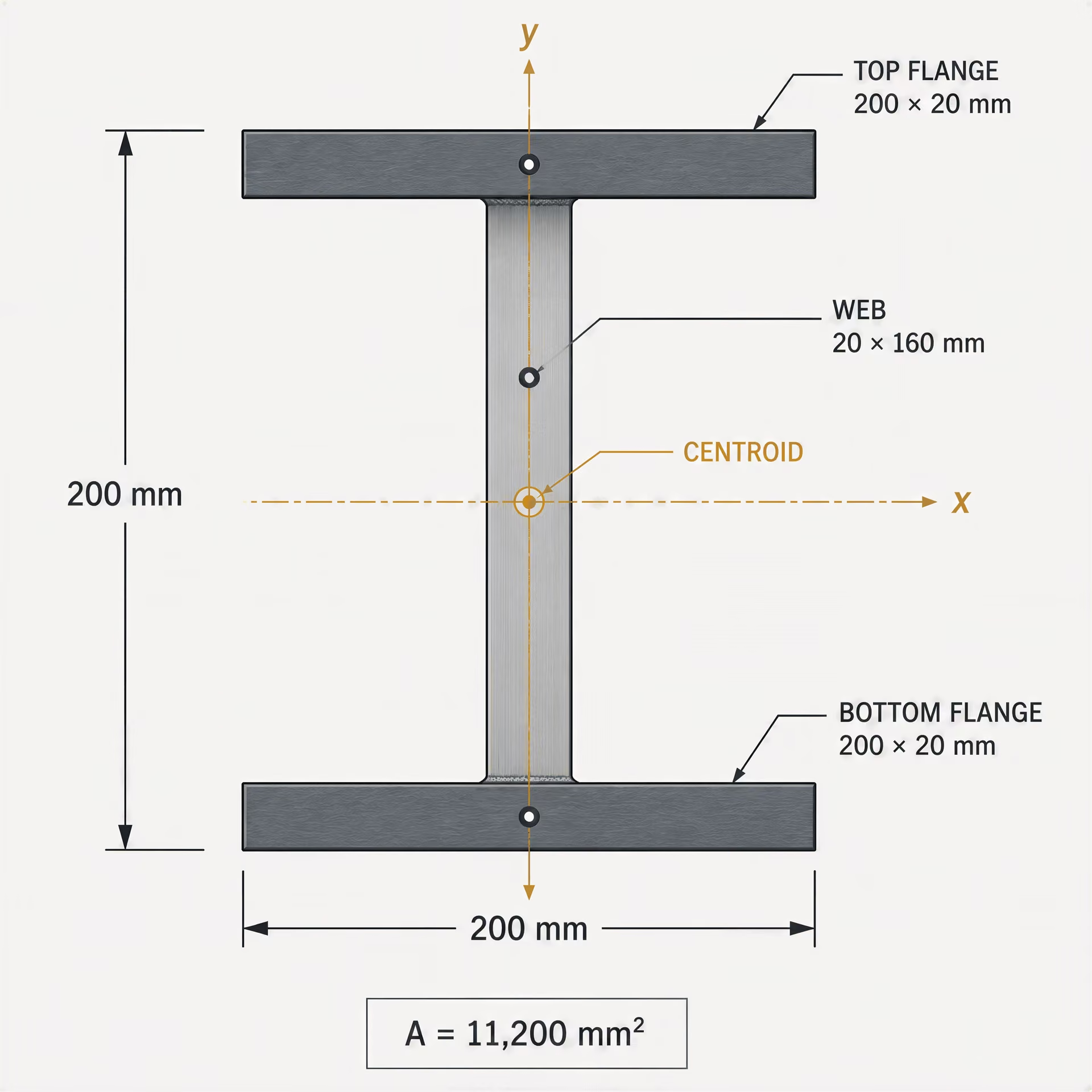
A Worked Calculation Workflow for a Built-Up Steel Section
A built-up section should be calculated as geometry before it is treated as a steel member. The steel grade does not alter the gross area, centroid, second moments of area, or elastic section moduli for a given set of dimensions. Grade designations such as ASTM A992 or S355 affect resistance and design checks; they do not make the same cross-section geometrically larger or stiffer.
- Top flange
- 200 × 20 mm
- Web
- 20 × 160 mm
- Bottom flange
- 200 × 20 mm
- Overall depth
- 200 mm
- Total area
- 11,200 mm²
The following example uses a symmetric welded I-section assembled from three rectangles:
- Top flange: mm
- Web: mm
- Bottom flange: mm
- Overall depth: mm
The dimensions describe the geometry only. Whether the steel is ASTM A992, S275, S355, or another grade is a separate question.
Decompose the cross-section
Start with a dimensioned sketch. Show the overall width and depth, each plate thickness, the origin, and the positive directions of the axes. Let be horizontal and vertical, with the origin at the lower-left corner of the overall bounding rectangle. For section-property work, it is also useful to mark the eventual centroidal axes and .
| Component | Width (mm) | Height (mm) | Area (mm²) | Centroid x,y (mm) |
|---|---|---|---|---|
| Bottom flange | 200 | 20 | 4,000 | 100, 10 |
| Web | 20 | 160 | 3,200 | 100, 100 |
| Top flange | 200 | 20 | 4,000 | 100, 190 |
Divide the section into non-overlapping rectangles. For the example:
| Component | Width (mm) | Height (mm) | Area (mm²) | Centroid (mm) |
|---|---|---|---|---|
| Bottom flange | 200 | 20 | 4,000 | 100, 10 |
| Web | 20 | 160 | 3,200 | 100, 100 |
| Top flange | 200 | 20 | 4,000 | 100, 190 |
The web begins at and ends at , so its centroid is at . The total area is
This partition deliberately avoids overlap. A common error is to use the overall rectangle and then subtract only the side voids without checking whether the resulting regions match the actual weld-up. For a section containing a hole, slot, cope, or cut-out, represent the missing region with a negative area. Its first moments and inertia terms must also carry negative signs.
The decomposition can use triangles, circles, hollow circles, or other primitives when those better describe the shape. A hollow circular hole, for example, is handled as an outer positive circle and an inner negative circle. The same sign convention applies to every subsequent summation.
Calculate centroid and inertia
First calculate the centroid from the first moments:
\[ \bar{x}=\frac{\sum A_i x_i}{\sum A_i}, \qquad \bar{y}=\frac{\sum A_i y_i}{\sum A_i}. \]
For this section,
Because the top and bottom flanges are identical and placed symmetrically,
The centroid is therefore at the geometric center. Do not assume that result for an unsymmetrical built-up section. Calculate it.
For each rectangle, calculate its local centroidal inertias:
\[ I_{x,i,\text{local}}=\frac{b h^3}{12}, \qquad I_{y,i,\text{local}}=\frac{h b^3}{12}. \]
Then transfer each value to the common centroidal axes using the parallel-axis theorem:
where \(d_{y,i}=y_i-\bar y\) and \(d_{x,i}=x_i-\bar x\).
For , the flange centroid distances are mm and the web distance is zero. The local flange inertia is
and the local web inertia is
Thus,
For , every component has \(x_i=\bar x=100\) mm, so no horizontal transfer term is needed:
The product of inertia is
Each rectangle has zero local product of inertia when its sides are parallel to the axes. Here, for all three components, so
That result matters. The selected centroidal axes are also principal axes for this doubly symmetric section.
The elastic section moduli follow from the extreme-fibre distances:
\[ S_x=\frac{I_x}{c_y}, \qquad S_y=\frac{I_y}{c_x}. \]
The extreme fibres are mm from both centroidal axes:
These are elastic section moduli. They are not plastic moduli, which require a plastic-neutral-axis calculation and area redistribution. They are also not the same as the radii of gyration:
The polar moment about the centroid, for these perpendicular and axes, is
That identity does not turn into the torsional constant . For the same thin-walled open I-shape, a preliminary Saint-Venant estimate is
Using the two flange plates and the web,
This is much smaller than , as expected for an open section. The approximation ignores some junction and thickness details, so it should not replace a code table, a validated thin-wall calculation, or a finite-element section-property method. The warping constant requires a separate warping calculation or a documented reference value; it cannot be obtained by relabelling , , or .
For a standard rolled section, compare the hand result with the exact profile and edition in the relevant table. The American Institute of Steel Construction states that AISC Shapes Database v16.0, published in 2023, gives dimensions and properties in U.S. customary and metric units, while Part 1 of the 16th Edition Steel Construction Manual is its reference section for standard dimensions and geometric properties. In Europe, SCI P363, commonly called The Blue Book, reports area, second moments, elastic and plastic moduli, radii of gyration, , and . EVS-EN 10365:2026 specifies nominal dimensions and masses; it is not, by itself, a replacement for a sectional-property table.
Verify against symmetry and software
Check symmetry before trusting arithmetic. The equal flanges place the centroid at mid-depth, and the equal left and right widths place it on the vertical centerline. Since the section is symmetric about both axes, must be zero when the axes are centroidal and aligned with the symmetry axes. A nonzero result signals a misplaced component coordinate, an overlap, an omitted plate, or a sign error.
Check units next. If dimensions are entered in millimetres, area is in , second moments and are in , section moduli are in , and radii are in millimetres. European tables often use centimetres for calculated properties; ArcelorMittal’s 2024 explanatory notes identify metre-based surface-area units and decimetre-based units for warping constants. A direct comparison without conversion can be wrong by factors of , , , or more.
An independent check can be made in Missouri S&T’s MDSolids section-properties module, documented in 2024. Enter the three rectangles as a generic composite shape, or enter the outside rectangle and subtract the two voids if that matches the chosen partition. Compare , centroid coordinates, , , , section moduli, radii of gyration, and principal moments. MDSolids reports those quantities for generic and standard steel shapes.
Abaqus provides a useful definition check: its 2024 documentation describes and as integrals of squared coordinate distances over the cross-sectional area, and as the integral of the product of coordinate distances. Software may reverse axis labels, change the sign convention for , or report properties about a different origin. A disagreement may therefore reveal a wrong axis, an omitted negative area, a centroid error, a unit mismatch, or a different definition such as gross versus net area, elastic versus plastic modulus, or Saint-Venant versus polar inertia. Inspect the input geometry and property definitions before changing the hand calculation.
Software, Numerical Integration, and Principal Properties
Generic-section calculators
A generic-section calculator evaluates geometry. It does not decide whether a steel member passes a design check, which limit state governs, or whether a particular grade is suitable. Changing the designation from ASTM A992 to ASTM A572 Grade 50 changes the material resistance specified by the design standard; it does not change the area, centroid, second moment of area, or torsional constant of an unchanged cross-section. Those quantities come from the boundary coordinates and material-region geometry.
Missouri S&T’s MDSolids section-properties module illustrates the range of outputs that a calculator may provide. Its 2024 documentation identifies centroidal location, second moments of area, section modulus, radius of gyration, plastic modulus, polar moment of inertia, and principal moments for generic and standard steel shapes. These results answer separate questions. Area measures how much cross-sectional material exists. and measure the spread of that area about specified centroidal axes. Elastic section modulus relates that spread to the extreme-fibre distance, while plastic modulus comes from a fully yielded stress-block construction. Radius of gyration is a derived length, not another inertia.
The same warning applies to polar and torsional outputs. The polar moment describes area distribution about a point and is not, by itself, the Saint-Venant torsional constant . For open and closed sections, depends on the torsion problem and boundary conditions; warping constant describes restrained longitudinal warping and has different units again. A software window that places these values beside one another has not made them interchangeable.
For a built-up section, the calculation can still be checked by hand. Compute each component area and centroid, find the composite centroid from the first moments, then apply the parallel-axis theorem to each component’s local inertia. The University of Michigan’s recitation presents this component-area method. Rectangles, triangles, circles, and hollow circles provide useful test cases before a profile with tapered flanges, fillets, holes, or cut-outs is trusted. A comparison against AISC Shapes Database v16.0, published by the American Institute of Steel Construction in 2023, should use the exact shape designation and edition. AISC states that the database supplies dimensions and section properties in U.S. customary and metric units; it is not a license to infer properties for a similar-looking section.
A unit check is non-negotiable. Area may be in , inertia in , section modulus in , and radius in millimetres. ArcelorMittal states in its 2024 explanatory notes that European calculated properties are generally reported in centimetres, with surface area and warping constant using metre- and decimetre-based units respectively. The Blue Book from the Steel Construction Institute reports area, second moments, elastic and plastic moduli, radii of gyration, torsional constants, and warping constants for European sections. EVS-EN 10365:2026 specifies nominal dimensions and masses for hot-rolled channels, I sections, and H sections; it is not the same document as a table of calculated section properties.
Finite-element beam-section definitions
Finite-element programs commonly derive beam-section properties by numerical integration over a discretized region. Abaqus documentation, updated in 2024, defines centroidal properties by integrating squared coordinate distances for and , and the product of coordinate distances for . In schematic form,
\[ I_{11}=\int_A y^2\,dA,\qquad I_{22}=\int_A x^2\,dA,\qquad I_{12}=\int_A xy\,dA. \]
The symbols depend on the program’s local coordinates. One solver’s may correspond to the quantity commonly called , so the label alone is insufficient. Inspect the coordinate diagram and sign convention.
Numerical integration is especially useful for curved boundaries, rolled fillets, perforated plates, imported CAD outlines, and sections assembled from many material regions. The program divides the region into cells or section elements, evaluates the required coordinates and weights, and sums their contributions. Mesh refinement should produce converging centroid, area, and inertia values. A coarse mesh can erase a small hole, distort a fillet, or shift the centroid enough to affect a thin-walled section. A visually smooth mesh is not evidence of property convergence.
A finite-element beam definition also contains choices that geometry alone cannot settle. Check whether the section is assigned as solid, thin-walled, open, or closed; whether shear areas are calculated or entered; and whether torsional and warping properties are derived from the same discretization. Confirm every material region. A steel flange, grout pocket, weld idealization, void, coating, or composite insert must be assigned deliberately. If a region is omitted, duplicated, or assigned the wrong material in a composite section, the reported stiffness and mass may be wrong even when the outer outline looks correct.
Most importantly, identify the property basis: gross, net, effective, elastic, or plastic. Gross area includes the defined full section. Net area may remove bolt holes or other deductions. Effective properties may reflect local-buckling rules, while elastic and plastic section moduli describe different stress distributions. A section-property solver generally calculates the requested mathematical quantity; it does not determine effective width under ANSI/AISC 360-16, classify a plate under Eurocode rules, or perform a member buckling check. ANSI/AISC 360-16 identifies , , , , , and as steel-design quantities, but the design provisions govern how those quantities are used.
Principal moments and rotated axes
When , the chosen centroidal axes are not principal axes. Rotating the axes through an angle removes the product of inertia at the principal orientation. The principal moments are the eigenvalues of the centroidal inertia matrix:
The sign convention for affects the reported angle, so software results must be read with the program’s axis definition. For a doubly symmetric I-section, the usual centroidal symmetry axes are already principal axes and . An unequal angle, channel, skewed plate, or asymmetric cut-out generally requires a rotation.
Principal properties are not automatically the properties required for design. A column may buckle about the weak principal axis, while beam bending is specified about a building or member axis. A shell or beam model can also rotate its local section axes relative to global coordinates. Record both systems, then transform forces, moments, and section properties consistently. Before accepting a result, refine the mesh, verify orientation, inspect material-region assignments, check units, and compare simple limiting cases with MDSolids or a standard table. Software performs the arithmetic. The engineer still defines the geometry, selects the property basis, and decides what the numbers mean.
Accuracy, Rounding, Tolerances, and Profile Identification
A section-property value is only meaningful when its geometric definition is known. The value of , for example, depends on the cross-sectional shape, the reference axis, and the unit system. It is not a generic label attached to an I-shaped member. A published may describe a hot-rolled European HEA section, a U.S. W-shape, an idealized thin-walled section, or a measured specimen. Those are not interchangeable descriptions.
Nominal dimensions versus measured dimensions
A standard designation normally refers to nominal dimensions. EVS-EN 10365:2026 specifies nominal dimensions and masses for hot-rolled channels, I sections, and H sections; it does not claim that every manufactured section has perfectly sharp corners, exactly constant thickness, or dimensions with unlimited precision. A nominal HE 200 A, for instance, is identified by its standard designation and nominal dimensional series, while the actual flange thickness, web thickness, depth, and corner geometry are subject to manufacturing tolerances.
That distinction explains why a hand calculation can disagree with a table even when the arithmetic is correct. A simple calculation may represent an I-section as two rectangles for the flanges and one rectangle for the web. The manufactured profile contains fillets between web and flange, flange or web tapers, and corner radii. Removing or adding those regions changes the area and centroid, which then changes , , section moduli, and radii of gyration. The effect is often small for area but more consequential for a second moment because material far from the centroid contributes according to the square of its distance.
Three geometries should be kept separate:
1. Nominal standard geometry: dimensions assigned by the profile standard or section table. 2. Measured mill geometry: dimensions recorded from a particular rolled member, including its actual radii, thicknesses, taper, and deviations. 3. Idealized analysis geometry: a simplified model selected for a hand calculation, finite-element model, or preliminary design.
A tabulated property usually corresponds to a defined calculation model based on nominal dimensions and profile geometry, not to a random tape measurement from one beam. If a measured flange is 1.5 mm thicker than its nominal value, the resulting area and inertia may differ from the published values. A measured value is not automatically more correct; it answers a different question.
The same issue applies to built-up sections. If two plates are modeled as touching rectangles, the calculation may omit weld metal, gaps, cope cuts, bolt holes, or connection plates. For a built-up section, component areas, first moments, centroid coordinates, and the parallel-axis theorem must be applied to the stated geometry. The result belongs to that model, not necessarily to a catalogued rolled section.
Software does not remove the need to define the geometry. Abaqus documentation defines centroidal properties through area integration: and integrate squared coordinate distances, while integrates the product of coordinate distances. Missouri S&T’s MDSolids similarly reports centroid location, second moments, section modulus, radius of gyration, plastic modulus, polar moment, and principal moments for specified shapes. These outputs are precise for the input geometry, but precision in the display does not make uncertain input dimensions accurate.
Rounding and significant figures
Rounding should occur after the calculation, not during every intermediate step. Replacing a flange thickness of 9.8 mm with 10 mm before calculating a second moment can produce a noticeable difference, particularly when the flange lies far from the centroid. Rounding the final result to the precision supported by the source is more defensible than reporting from dimensions given only to the nearest millimetre.
Significant figures should reflect both dimensional accuracy and the purpose of the calculation. A design check may need more retained digits internally than a drawing note, while a preliminary comparison may reasonably show . Do not infer manufacturing accuracy from extra decimal places in a spreadsheet.
Unit conversion requires particular care because section properties have different dimensions. Area scales with length squared, second moments and torsional constants with length to the fourth power, section moduli with length cubed, and radii of gyration with length. A conversion mistake in is therefore much larger than a simple millimetre-to-metre mistake. European tables commonly report calculated properties in centimetres; ArcelorMittal states that surface area and warping constant use metre- and decimetre-based units respectively. The unit printed beside each column must be read, not assumed.
Rounding also affects comparisons between sources. One table may print to three significant figures and another to six, although both used the same geometry. Small discrepancies should first be checked against units, axis orientation, fillet treatment, and displayed precision before being treated as evidence of an error.
Edition and designation control
Every property value used in a calculation should carry five identifiers: the exact shape designation, the governing standard, the edition or database version, the axis convention, and the table or source location. Add the unit system. “W310 ” is incomplete; “W310×97, AISC Shapes Database v16.0, U.S. customary units, major centroidal axis, Part 1 table” is traceable.
The American Institute of Steel Construction states that AISC Shapes Database v16.0, published in 2023, provides dimensions and properties in U.S. customary and metric units. AISC Part 1 is the reference section of the 16th Edition Steel Construction Manual for tabulated dimensions and geometric properties. ANSI/AISC 360-16 defines quantities including , , , , , and , but the specification does not make an unspecified profile designation identifiable.
For European sections, SCI P363, The Blue Book, provides dimensions and sectional properties, including area, second moments, elastic and plastic section moduli, radii of gyration, torsional constants, and warping constants. Its profile family and designation must be retained. Do not copy an value from an HEA table into a calculation for an HEB, W-shape, or another profile family simply because the nominal depth appears similar. Do not mix an EN 10365 nominal dimension with a U.S. table’s property convention without checking the underlying geometry and axes.
Steel grade does not alter a geometric section property. S275, S355, ASTM A572 Grade 50, and ASTM A992 describe material or product requirements; changing the grade changes resistance calculations and design checks, not the area or inertia of an unchanged section. If a source shows different geometry for different grades, the difference comes from the selected product or manufacturing standard, not from steel becoming geometrically stronger.
How Section Properties Enter Steel Design Checks
Section properties enter a design check only after the section, material, loading, restraints, and applicable standard have been identified. They describe geometry, not strength. A gross area of remains that area whether the steel is ASTM A992 or ASTM A36; the grade changes quantities such as yield stress and tensile strength , not the calculated dimensions of the cross-section.
That distinction prevents a common error: selecting a larger numerical value because it “looks stronger” without checking what the value represents. Area , second moments of area and , section moduli , , , and , radii of gyration and , torsional constant , and warping constant have different units and enter different limit states.
ANSI/AISC 360-16 defines the named U.S. section-property quantities, including , , , , , and . AISC Part 1, Dimensions and Properties, is the reference section of the 16th Edition Steel Construction Manual for tabulated dimensions and geometric properties. The AISC Shapes Database v16.0, issued by the American Institute of Steel Construction in 2023, provides those dimensions and properties in U.S. customary and metric units. The exact shape designation and database edition still matter: a W14×90 is not interchangeable with another W14 shape, even when the nominal depth appears similar.
Axial compression and radius of gyration
For a concentric axial force, the gross area is the first geometric quantity considered. Average direct stress is represented by , subject to the applicable resistance factors, yielding or rupture provisions, and any reductions required for holes, slender elements, or other specified conditions. Area therefore relates directly to the amount of material carrying axial force, but it does not describe how that material is distributed away from the centroid.
That distribution controls column buckling. The radius of gyration is
\[ r_x=\sqrt{\frac{I_x}{A}}, \qquad r_y=\sqrt{\frac{I_y}{A}}. \]
For a member length , the corresponding slenderness ratios are commonly expressed using and , where represents the effective-length condition. The smaller radius usually produces the more critical flexural-buckling axis because the same member length generates a larger slenderness ratio. A wide-flange section may have a substantial area yet remain vulnerable about its minor axis because is much smaller than .
This is why area and radius of gyration cannot be substituted for one another. Increasing flange width can raise , , or both, while adding material near the centroid may increase with less improvement in buckling resistance. Boundary conditions, bracing, residual stress, initial crookedness, load eccentricity, and local slenderness also affect the compression resistance. The geometric property supplies an input; it does not determine the final member resistance by itself.
Bending resistance and section modulus
The second moment of area measures resistance to curvature, or flexural stiffness, rather than direct material strength. For elastic bending about the -axis,
where is the distance from the neutral axis. The elastic section modulus is
with equal to the distance from the neutral axis to the extreme fiber. The corresponding bending stress relation is . The same definitions apply about the -axis.
Because includes squared distance from the axis, material placed far from the neutral axis contributes strongly to flexural stiffness and elastic bending resistance. This explains the efficiency of I-shaped sections: their flanges place much of the area at large distances from the major-axis neutral axis, while the web connects those flanges and carries shear.
Plastic bending uses a different property. The plastic section modulus is based on a fully yielded stress distribution separated by the plastic neutral axis, not on the extreme-fiber distance used for . For a compact section capable of developing plastic behavior, a design expression may involve , whereas an elastic limit expression involves , subject to the provisions of the governing standard. is not a replacement for , and neither is a material-strength value.
The applicable resistance also depends on flange and web slenderness, lateral bracing, unbraced length , loading position, end restraint, and lateral-torsional buckling. A section with a high can still have reduced bending resistance if its compression flange is insufficiently braced. AISC tables therefore need to be read alongside ANSI/AISC 360-16 provisions rather than treated as a complete design result.
European tables use the same physical distinctions under different presentation conventions. The Steel Construction Institute’s Blue Book provides area, second moments, elastic and plastic moduli, radii of gyration, , and for European sections. EVS states that EVS-EN 10365:2026 specifies nominal dimensions and masses of hot-rolled channels, I sections, and H sections; it does not by itself replace a sectional-property table. ArcelorMittal reports that calculated European properties are generally given in centimetres, while surface area and warping constant use metre- and decimetre-based units respectively. Unit conversion errors can change a result by orders of magnitude.
Torsion, buckling, and interaction
Torsion introduces properties that are often omitted from simplified beam discussions. The torsional constant describes Saint-Venant torsional behavior and is strongly influenced by whether a section is open or closed. Thin-walled closed sections generally resist uniform torsion more effectively than open I, channel, or angle sections of comparable area because a closed wall can develop a circulating shear flow.
The warping constant describes resistance associated with restrained longitudinal warping. It becomes important for open sections subjected to torsion, especially when end conditions, diaphragms, bracing, or concentrated loads prevent the cross-section from warping freely. and therefore do not carry the same meaning: one is not a general substitute for the other. The units also differ. Inconsistent conversion of , often reported in length to the sixth power, can invalidate a torsional or lateral-torsional calculation.
Lateral-torsional buckling couples major-axis bending with lateral displacement and twist. The response depends on , , , unbraced length, moment gradient, load application point, and end restraint. A beam can possess a large major-axis section modulus while having limited resistance because its compression flange is free to move laterally and the section can twist. Torsional buckling and flexural-torsional buckling in compression members similarly depend on more than , , and .
Combined axial force, bending, and torsion require interaction checks prescribed by the applicable design standard. Connection eccentricity, bolt or weld arrangement, local load introduction, shear area, and member continuity can alter the internal actions used in those checks. Product of inertia and principal-axis properties become relevant when the geometric axes do not coincide with the principal axes, particularly for unsymmetric angles, channels, and built-up members.
For verification, hand calculations based on component areas, centroid coordinates, first moments, and the parallel-axis theorem should agree with a trusted table or software result. Abaqus documentation defines and by integrating squared coordinate distances over the area and by integrating the product of coordinate distances; Missouri S&T’s MDSolids independently reports centroid, inertia, moduli, radii, polar inertia, and principal properties. Such checks catch swapped axes, wrong units, and mistaken profile dimensions before a geometric quantity enters a steel design check.
Steel Grade, Metallurgy, and What Geometry Does Not Tell You
Shape designation versus steel grade
A shape designation identifies geometry; a steel grade designation identifies material requirements. They are not interchangeable. An HEA 200, W14×90, or L 100 × 100 × 10 describes a rolled profile and its nominal dimensions. It does not, by itself, state the yield strength, tensile strength, chemical composition, impact-toughness requirement, or weldability classification of the steel.
Changing the grade designation does not change the geometric section properties of an unchanged cross-section. If the same I-shaped profile has the same flange width, web depth, flange thickness, and web thickness, its gross area , centroid, , , elastic section moduli, radii of gyration, torsional constant , warping constant , and product of inertia remain the same geometric quantities. A higher specified yield strength does not make that profile acquire a larger , and it does not increase its radius of gyration.
This distinction is basic but often lost in tables and software menus. A section property is calculated from the location and distribution of material in the cross-section. Abaqus describes the centroidal second moments by integrating squared coordinate distances over the area: and measure those squared distances, while integrates the product of coordinate distances (Abaqus Documentation, 2024). The calculation contains geometry, axes, and units—not a yield-strength value.
A shape designation can still be incomplete. “200 I-section” may omit the section series, manufacturing standard, mass designation, tolerances, and edition. A U.S. W14×90 and a European HE 360 B are not identified by comparable labels merely because both are I-shaped. The exact profile standard must be recorded before a tabulated area or inertia is accepted.
Geometry-independent and grade-dependent inputs
Dimensions, nominal mass per unit length, gross area, centroid coordinates, second moments of area, section moduli, radii of gyration, polar moment, , , , shear areas, and plastic modulus are primarily section-description inputs. For a homogeneous prismatic section, they follow from its cross-sectional geometry and the selected reference axes. Built-up calculations use component areas, first moments, centroid coordinates, and the parallel-axis theorem. They do not require the steel to be S275 rather than S355, or ASTM A36 rather than ASTM A992/A992M.
Mass requires one qualification. Cross-sectional area is geometric; mass per unit length also depends on density and on whether the tabulated value is based on nominal dimensions. Manufacturing tolerances, corner radii, fillets, holes, coatings, and corrosion can therefore produce differences between a nominal calculation and an actual measured member. Those differences are geometric or physical-condition effects, not evidence that grade strength changed the section property.
Material specification controls a different group of inputs. These include specified yield strength, tensile strength, elongation or other ductility measures, fracture toughness, chemical composition, delivery condition, weldability-related requirements, and corrosion behavior. Their effect appears in resistance calculations, connection checks, fracture assessment, welding procedures, durability assessments, and fire or temperature-related design checks. They do not replace , , , or .
A design may use the same geometry with different resistance values when the applicable material specifications differ. That conclusion must come from the cited specification and design standard; it should not be inferred from a grade name alone. For example, a record naming ASTM A992/A992M must be checked against the requirements of that specification, while a record naming EN 10025-2 S355 must be checked against the applicable edition and product requirements of EN 10025-2. “S355” or “A992” without the governing standard and product form is insufficient evidence for a design assumption.
Corrosion requires separate treatment because it can eventually alter geometry. The original grade designation does not cause a change in or , but metal loss reduces thickness and may reduce area, stiffness, section modulus, and torsional properties. The engineer must model the remaining cross-section and separately assess the material and environmental requirements.
Structural steel documentation
A complete design record identifies both the section standard and the material specification. It should state the profile designation, nominal dimensions or mass designation, standard and edition, axis convention, units, and source of the section properties. It should also state the material grade, product standard, specification edition, and any supplementary toughness or delivery requirements that govern the design.
For U.S. work, the American Institute of Steel Construction states that AISC Shapes Database v16.0 provides dimensions and section properties in U.S. customary and metric units (AISC, 2023). AISC Part 1, Dimensions and Properties, is the reference section of the 16th Edition Steel Construction Manual for tabulated dimensions and geometric properties. ANSI/AISC 360-16 defines quantities including , , , , , and (AISC, 2021). These references supply geometry and design definitions; the material specification supplies the steel properties.
European records need the same separation. The Steel Construction Institute’s Blue Book provides calculated properties such as area, second moments, elastic and plastic section moduli, radii of gyration, torsional constants, and warping constants (SCI, 2024). EVS-EN 10365:2026 specifies nominal dimensions and masses for hot-rolled channels, I sections, and H sections; it is not a substitute for a sectional-property table or a material-grade specification. Units also require checking: ArcelorMittal notes that European calculated properties are generally reported in centimetres, while surface area and warping constant use metre- and decimetre-based units respectively (ArcelorMittal, 2024).
Software output should preserve this audit trail. A calculated is meaningful only when the imported profile, axes, unit system, and geometric assumptions are known. A material grade added to the same model changes resistance inputs, not the section geometry.
Common Errors and a Verification Checklist
Using the wrong second moment can substantially distort predicted buckling or deflection. Limited evidence
Section-property errors often begin before any equation is entered. A drawing may show the correct profile, yet the calculation can still fail because the axes, units, standard edition, or property definition do not match the design check. The result is not a minor spreadsheet discrepancy: using the wrong second moment can change a buckling or deflection prediction by an order of magnitude.
Axis and unit mistakes
The most common error is swapping and . For a typical I-section, the major-axis second moment is much larger than the minor-axis value. If the member bends about its weak axis but the strong-axis value is entered, the calculated curvature and deflection will be far too small. The same mistake affects radii of gyration, elastic section moduli, plastic moduli, and any buckling calculation based on the selected axis.
Axis labels are not universal across every table or software package. One source may call the horizontal centroidal axis , while another uses 2; a finite-element program may define local 1 and 2 axes according to the section orientation. Abaqus states that centroidal and integrate squared coordinate distances, while integrates the product of coordinate distances (Abaqus Documentation, 2024). That definition must be reconciled with the drawing before values are copied.
Units create a second failure point. Area in , second moment in , and section modulus in cannot be combined with dimensions entered in millimetres without conversion. Since , a table conversion omitted in a spreadsheet can produce a factor-of-10,000 error. European tables commonly report calculated properties in centimetres; ArcelorMittal notes that surface area and warping constant also use metre- and decimetre-based units, respectively (ArcelorMittal, 2024). Read every column heading.
A mass table is not a property table. EVS-EN 10365:2026 specifies nominal dimensions and masses for hot-rolled channels, I sections, and H sections; it does not, by itself, provide every calculated value needed for bending, torsion, or buckling. The Steel Construction Institute’s Blue Book supplies sectional properties, including , elastic and plastic moduli, radii of gyration, , and . In the United States, AISC Shapes Database v16.0 provides dimensions and properties in U.S. customary and metric units, while AISC Part 1 is the reference section of the Steel Construction Manual for tabulated dimensions and geometric properties (AISC, 2023).
Confusing , , , , and
The symbol by itself is incomplete. It may mean a centroidal second moment about a specified axis, or , or appear in a software convention such as . The second moment has units of length to the fourth power and controls bending stiffness through . It is not a strength value.
The polar moment of area is commonly written , with
when and are perpendicular centroidal axes. It measures the distribution of area around a point and is useful in some circular-shaft and rotational calculations. It is not generally the torsional constant.
The torsional constant describes Saint-Venant torsional response. For a solid circular section, , but that equality should not be extended to I-sections, channels, angles, or thin-walled open sections. Their values can be far smaller than . Closed sections also develop different torsional behavior because shear flow can circulate around the enclosed cell. Warping constant , with units of length to the sixth power, concerns nonuniform torsion and restrained warping; it is not another form of . ANSI/AISC 360-16 defines and uses , , , , , and as separate section-property quantities (AISC, 2021).
Section modulus terminology causes another recurring mix-up. The elastic section modulus is obtained from the elastic second moment, for example
where is the distance from the neutral axis to the extreme fibre. The plastic section modulus, often denoted or , is based on the fully yielded plastic stress distribution. It is not , and it cannot be substituted merely because both have units of length cubed. For a symmetric rectangular section, the values have a simple relationship; for rolled sections with unequal flange and web geometry, the distinction matters.
Holes, cope cuts, and voids must be removed from area calculations. Fillets must not be ignored casually when comparing a hand model with a rolled-shape table. For a built-up section, the parallel-axis term is , where is the perpendicular distance between the component centroid and the assembled centroidal axis. Using the overall depth, a flange thickness, or a distance measured from the wrong reference axis produces a plausible-looking but incorrect result.
Independent checks before design use
A property should pass more than one test before it enters a design model. First, sketch the exact section, including holes, fillets, plates, weld additions, and the orientation used in the member. Mark the centroidal axes and identify whether they are principal axes. For an axis of symmetry, the product of inertia should be zero when the axes are aligned with that symmetry.
Next, calculate a simple benchmark independently. Rectangles, triangles, circles, and hollow circles provide useful checks for area, centroid, , , and section modulus. For a built-up shape, compute component areas and first moments, locate the centroid, then apply the parallel-axis theorem separately for each axis. A spreadsheet and a section-property program should not share the same hidden input or formula if they are being used as an independent comparison. Missouri S&T’s MDSolids resource, for example, reports centroid, second moments, section moduli, radii of gyration, plastic modulus, polar moment, and principal moments for generic and standard steel shapes (Missouri S&T, 2024).
Finally, record the exact source, profile designation, standard edition, units, axis labels, and whether the values are gross, net, elastic, plastic, Saint-Venant, or warping properties. A designation such as ASTM A992 or ASTM A36 changes material resistance and design checks; it does not change the geometric properties of the same section dimensions. Likewise, S355 under the relevant European product and design standards does not make a geometrically identical section acquire a different or .
Verification checklist
- Geometry Use a dimensioned sketch with orientation, holes, fillets, and centroidal axes.
- Source Record the table or calculation method and the applicable standard edition.
- Units Label every input and output explicitly.
- Axes Identify x, y, principal, local, and global axes.
- Independent check Compare with a hand calculation, software result, or matching table.
- Review Obtain qualified engineering review when the value affects a real member or connection.
Before a result informs a real structure, the checklist should require:
- a dimensioned sketch with orientation, holes, fillets, and centroidal axes;
- a citation for the source table or calculation method;
- the applicable standard and edition, such as AISC Shapes Database v16.0, the 16th Edition Steel Construction Manual, SCI P363, or EVS-EN 10365:2026;
- explicit units for every input and output;
- clearly labelled , , principal, local, or global axes;
- an independent hand calculation, software calculation, or tabulated comparison; and
- review by a qualified engineer when the value affects a real structural member or connection.
References
- [1] AISC Shapes Database v16.0. AISC Shapes Database, 2023. https://www.aisc.org/aisc/publications/steel-construction-manual/aisc-shapes-database-v160/
- [2] 16th Edition Steel Construction Manual, Part 1. Steel Construction Manual, 2023. https://www.aisc.org/aisc/publications/steel-construction-manual/