



1. What Heat-Treatment Distortion and Residual Stress Mean
Heat-treatment sequence
- Heating Temperature gradients create differential thermal expansion and may cause early plastic strain.
- Holding Austenite forms, carbon and alloying elements redistribute, and grain size develops.
- Quenching Surface-to-core cooling differences combine with phase-transformation strain and restraint.
- Tempering Martensite changes, some stress relaxes, and retained austenite may continue to transform.
Heat treatment changes more than hardness. During heating, holding, quenching, and tempering, a steel part experiences temperature gradients, phase transformations, volume changes, elastic strain, plastic flow, and changes in strength. Its final dimensions and internal stress state therefore emerge from a coupled thermomechanical and metallurgical process, not from temperature history alone.[1]Residual Stress and Distortion during Quench Hardening of Steels: A Review. Authors in the review. Journal of Materials Engineering and Performance, 2022.
A thin edge may cool and transform before the core. A carburized case may contract differently from a low-carbon interior. A casting may already contain stress from solidification before it enters the furnace. Quenchant movement, bath temperature, part orientation, section thickness, alloy hardenability, and even the machining sequence can alter the result. The 2022 review by authors in the Journal of Materials Engineering and Performance identifies interactions among heat transfer, phase transformation, geometry, section thickness, quenchant selection, and quench severity as controlling factors rather than independent variables (2022 review).
Dimensional distortion versus internal stress
Distortion is an unintended change in a part’s shape or dimensions. It includes bowing, bending, twisting, ovality, taper, local growth or shrinkage, and changes in flatness or runout. A quenched shaft that becomes banana-shaped has distorted. A bearing ring that changes from circular to oval has distorted, even if its average diameter changes very little. Distortion is detected by dimensional inspection, coordinate measurement, gauges, or comparisons with the pre-treatment geometry.
Residual stress is stress that remains within a body after the external load, temperature difference, or processing operation that produced it has ended. It is self-equilibrating: tensile and compressive regions coexist so that the component can satisfy overall force and moment balance without an applied load. A surface may be in compression while the subsurface is in tension, or the reverse. The component can appear straight while these stresses remain substantial.
| Stress source | Primary cause | Typical consequence |
|---|---|---|
| Thermal | Unequal expansion or contraction | Surface and core stress, bending, or warpage |
| Transformation | Different phase changes and transformation strains | Growth, shrinkage, ovality, or stress reversal |
| Hardening | Local yielding and evolving strength | Permanent strain, redistribution, and cracking risk |
ASM International’s chapter “Residual Stresses and Distortion in Quenched and Tempered Steels” separates thermal, transformation, and hardening residual stresses. Thermal residual stress develops when different regions contract by different amounts during cooling. Transformation residual stress arises when austenite changes into products such as martensite, bainite, or pearlite at different times and locations. Hardening residual stress reflects the interaction of these effects with the evolving strength and plasticity of the steel. These categories overlap in an actual part, but the distinction helps identify the source of a dimensional problem (ASM International).
A component can meet dimensional tolerances while retaining a severe internal stress field that later moves or damages the part.Strong evidence
Distortion and residual stress often occur together, but they are not interchangeable. A component can have visible warpage with relatively limited locked-in stress after substantial plastic relaxation. It can also meet dimensional tolerances while carrying a severe internal stress field. The latter condition is dangerous because later machining, grinding, welding, service loading, or thermal cycling can release or redistribute the stress. Metallurgy of Heat Treatment, preserved in the National Institute of Standards and Technology materials-data archive, describes how unrelieved quenching stresses can cause warpage during machining: removing material changes the balance that previously held the part in its measured shape (NIST materials-data archive).
This is why a final inspection conducted immediately after quenching does not fully describe dimensional stability. A gear may pass a runout check, then move during finish grinding. A plate may remain flat until one face is milled. A hardened shaft may show little change while supported, but bend after it is unclamped. Dimensional correctness at one stage is not proof that the stress state is harmless.
Why a part can be dimensionally correct yet highly stressed
A part remains dimensionally correct when the strains produced during treatment are compatible with its shape, restraints, and material response, even if internal stresses are high. Consider a long, uniform bar heated and cooled nearly symmetrically. Its surface and core may develop opposing stresses, yet the net bending moment can remain close to zero. The bar stays straight while tensile and compressive stresses balance across its section.
A similar result can occur in a ring or disk when the stress field is axisymmetric. The component may expand or contract uniformly enough to remain round, although radial and circumferential stresses are locked into the material. Dimensional measurement records the external consequence; it does not directly reveal the internal stress distribution.
The reverse is also possible. If one side cools faster, or if a thin flange transforms before a thick hub, incompatible strain produces bending or twisting. Some of the stress is relieved by plastic deformation, leaving a permanent shape change. The final part may therefore show obvious distortion even after much of the original stress has disappeared.
ASM’s Basic Principles and Design Guidelines for Heat Treating of Steel identifies minimizing distortion and undesirable residual stress as primary heat-treatment design criteria. That wording matters: reducing dimensional change alone is insufficient. A process that holds a part straight through severe fixturing may leave high stress that appears later as cracking, grinding damage, or service instability. The U.S. Department of Energy likewise links thermal and residual stresses in steel castings with distortion, cracking, rework, weld repair, dimensional error, and reduced service performance (DOE report).
Material history also changes the starting point. Prior forging, casting, welding, cold working, machining, carburizing, nitriding, or stress relief can alter grain structure, hardness, residual stress, and transformation behavior. The University of Iowa’s work on steel castings emphasizes that casting history must be included when predicting final dimensions and residual stresses. A heat-treatment simulation that begins with an assumed stress-free, uniform microstructure can therefore produce a precise answer to the wrong problem.
Elastic strain, plastic strain, and permanent shape change
Elastic strain Deformation that is recovered when the applied stress is removed, provided the material has not yielded.
Elastic strain is recoverable deformation. When stress is removed, the material returns toward its previous shape. During quenching, temperature differences and transformation strains first generate elastic stress, but only while the local stress remains below the temperature-dependent yield strength.
Plastic strain is permanent deformation produced when the local stress exceeds that changing yield strength. Hot steel yields readily during heating; colder, transforming regions may become strong enough to resist deformation, while neighboring regions continue to contract or transform. Because the yield strength, thermal expansion coefficient, and phase composition vary during treatment, the boundary between elastic and plastic behavior moves throughout the part.[2]Residual Stresses in Quenched Steel: Parts I and II. Authors of the IJMPT discussions. International Journal of Materials and Product Technology, 2005.
Permanent distortion results when plastic strains are spatially incompatible. If every region contracted equally, the part would simply become smaller. If one region contracts more than another and the difference cannot be accommodated elastically, the part bends, twists, or changes profile. Phase transformations add another source of strain: martensite formation, for example, involves a volume increase, while other transformations have different timing and magnitude. The 2005 International Journal of Materials and Product Technology discussion identifies nonuniform thermal gradients as a principal source of quench distortion and connects residual stress with microscale plastic deformation, quenchant conditions, surface and case hardening, and final grinding (Part I; Part II).
The Worcester Polytechnic Institute report expresses the same point as a coupled problem involving heat transfer, phase transformation, stress, strain, and microstructural change (WPI report). That is the useful starting position for the rest of this article: heat treatment does not merely impose a temperature schedule on steel. It creates a moving, interacting field of thermal and metallurgical strains, and the final dimensions are the visible remainder of that history.
2. The Three Principal Sources of Residual Stress in Heat-Treated Steel
Residual stress is stress that remains after the external loads and temperature gradients have been removed. Distortion is a dimensional change: bowing, ovality, growth, shrinkage, twist, or a change in flatness. The two outcomes are coupled, but they are not the same. A component can retain high residual stress while appearing dimensionally accurate, or it can distort after machining because removing material releases a previously balanced stress field.
ASM International separates heat-treatment residual stress into three principal sources: thermal stress, transformation stress, and hardening residual stress. This classification is useful because the mechanisms differ, even though they act at the same time in a real steel part. A phrase such as “quench stress” therefore hides the actual sequence of events. Heat transfer, phase transformation, section thickness, geometry, alloy hardenability, quenchant selection, and prior material history all determine which mechanism dominates at a particular location.

Thermal residual stress
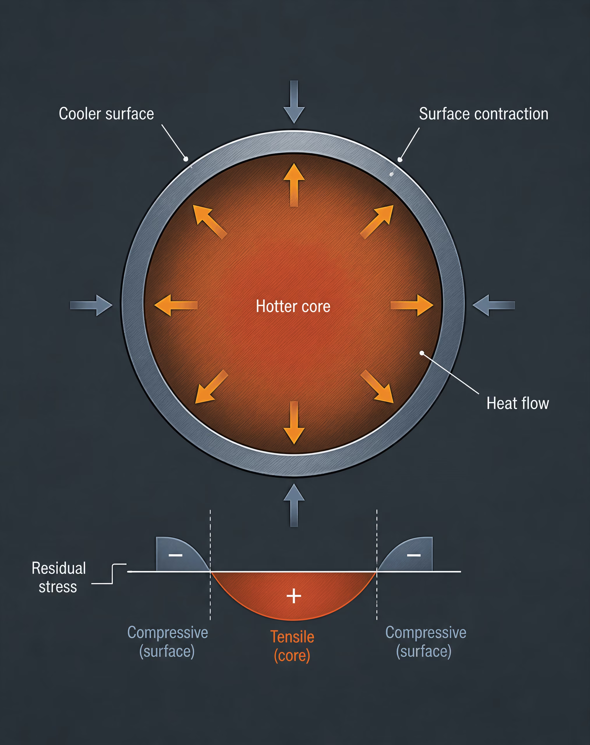
Thermal residual stress begins with nonuniform heating or cooling. Steel expands when heated and contracts when cooled, but a component does not change temperature everywhere at the same rate. The surface responds first; the core lags behind. A thin edge, a heavy hub, a sharp corner, and a drilled hole each develop different temperature histories.
During cooling, a hot interior tends to remain expanded while the colder surface contracts. The surface is restrained by the hotter core and may therefore enter compression, while the core develops tensile stress. If the surface cools and contracts after the core has already cooled, the stress pattern can reverse. The final sign is not fixed by the word “quench.” It depends on the time sequence, local geometry, thermal conductivity, quench severity, and whether yielding occurred during the transient.
Heating can create the opposite sequence. A rapidly heated surface attempts to expand against a colder interior and may yield in compression. On later cooling, that plastically changed surface can leave tensile residual stress. Furnace uniformity, loading arrangement, part orientation, and contact with fixtures all affect the temperature field before quenching begins.
ASM’s Basic Principles and Design Guidelines for Heat Treating of Steel identifies minimizing distortion and undesirable residual stresses as primary heat-treatment design criteria. The point is practical: thermal gradients are not merely a temperature-control issue. They produce incompatible strains, and those strains can become permanent when the local stress exceeds the temperature-dependent yield strength.
Nonuniform thermal gradients during quenching are identified as a principal source of quench distortion in the International Journal of Materials and Product Technology. A long slender shaft may bend because one side cools faster than the other. A ring may become oval because its outer and inner surfaces exchange heat at different rates. A plate may dish when its faces experience unequal cooling. The residual stress can vary from tensile to compressive across a few millimetres, so a single average value says little about cracking risk or later machining movement.
Transformation residual stress
Transformation residual stress arises when steel changes crystal structure and therefore changes volume and mechanical response. On cooling from austenite, regions may transform to ferrite, pearlite, bainite, or martensite at different temperatures. Martensitic transformation produces a significant transformation strain, while the amount and direction of dimensional change also depend on carbon content, alloying elements, retained austenite, and the fraction of each constituent.
The surface of a quenched part often cools and transforms before the core. If the surface forms martensite while the interior remains austenitic, the surface expands while the core is still hot and relatively compliant. Later, the core transforms and expands, but the already hardened surface resists that movement. The stress state can consequently change during the quench. A surface that was initially tensile may finish in compression, or the reverse, depending on transformation timing and restraint.
This is why transformation stress cannot be treated as a uniform “martensite expansion” correction. Transformation strain is local, and the surrounding material may be at a different temperature, phase fraction, and yield strength. A hardened case over a softer core behaves differently from a through-hardened section. Carburized, nitrided, and induction-hardened parts also develop steep microstructural and strain gradients. Retained austenite may transform later during tempering, service, grinding, or storage, producing additional dimensional change and stress relaxation.
Transformation also affects stress through transformation plasticity. Under an applied or internally generated stress, a transforming region can deform plastically at stresses below the ordinary yield strength. The transformation then accommodates part of the imposed strain, but not necessarily in a way that preserves the original shape. Local transformation plasticity can contribute to bending, ovality, and changes in straightness.
The 2022 review “Residual Stress and Distortion during Quench Hardening of Steels: A Review,” published in the Journal of Materials Engineering and Performance, describes residual stress and distortion as outcomes of interacting heat transfer, phase transformation, geometry, section thickness, quenchant selection, and quench severity. That interaction is central. A faster quenchant may increase the thermal gradient, alter the transformation sequence, and produce a harder surface at the same time; separating those effects after the fact is difficult.
Hardening and plastic-deformation stress
The third source is stress created when local yielding, work hardening, or restraint prevents compatible deformation. Steel is not equally strong throughout a heat treatment. Yield strength changes sharply with temperature and microstructure. Austenite at quenching temperature can deform readily, whereas newly formed martensite is much stronger and less ductile. A section may therefore yield in one region and remain elastic in another.
Suppose a surface layer contracts during cooling but is restrained by a hotter core. If the surface exceeds its instantaneous yield strength, it undergoes permanent plastic strain. When the temperature field later becomes more uniform, elastic recovery cannot remove that plastic strain. The remaining elastic mismatch is residual stress. If one side of a component yields more than the other, the mismatch appears as distortion as well as stress.
Hardening increases this effect by locking in local differences. A martensitic case may resist the contraction of a less-hardened core; a soft core may accommodate some strain, but continued cooling and transformation can reverse the stress distribution. Quench uniformity, agitation, quenchant temperature, and part placement determine whether nominally identical sections harden in the same way. Final grinding can add another layer of near-surface stress through local heating and mechanical deformation.
The International Journal of Materials and Product Technology attributes residual stresses in quenched steel to microscale plastic deformation and discusses the effects of quenchant conditions, surface and case hardening, and final grinding. This mechanism explains why stress measurements at the surface cannot be assumed to represent the core. It also explains why stress relief by tempering, thermal treatment, or controlled mechanical methods must be selected with the material condition and required dimensions in mind.
These three sources overlap continuously. Thermal stress changes the transformation path; transformation strain changes the thermal and mechanical restraint; local yielding redistributes both. Casting history, forging strain, segregation, machining, and prior normalizing or annealing alter the starting condition. The University of Iowa and U.S. Department of Energy reports connect these residual stresses with distortion, cracking, rework, weld repair, dimensional errors, and reduced service performance. The NIST materials-data archive further notes that unrelieved quenching stress can cause warpage during machining when material removal disrupts the original balance.
A valid assessment must therefore ask where the stress is tensile or compressive, how its magnitude varies through the section, and how it changes from one feature to another. The answer may differ at the surface, case-core boundary, mid-thickness, bore, fillet, and end face. “Quench stress” is a process label, not a mechanism.
3. Heating: The First Stage of Distortion Risk
Distortion does not begin when a steel component enters the quench. It begins as soon as different regions of the part reach different temperatures and attempt to expand by different amounts. The resulting stress may remain elastic, or it may exceed the local yield strength and produce permanent strain. Either way, the heating cycle establishes the mechanical condition that later interacts with transformation and quenching.
Residual stress and distortion are related but not identical. Residual stress is self-balancing stress left inside the part after external loads and temperature differences have disappeared. Distortion is a dimensional or shape change. A component can retain substantial residual stress without obvious warpage, while a small amount of local plastic strain can produce measurable bending or loss of roundness. ASM International identifies thermal, transformation, and hardening residual stresses as separate contributors in quenched and tempered steels, and treats minimizing distortion and undesirable residual stress as primary heat-treatment design criteria.
Temperature gradients during furnace heating
A furnace may have a stable set temperature while the workpiece remains far from thermal uniformity. The surface absorbs heat first; the core responds later because heat must conduct through the section. A thin edge, tooth, rib, or boss can approach the furnace temperature while a thick hub or plate center is still relatively cool. The hot region tries to expand, but the colder interior restrains it. This produces a changing pattern of compressive and tensile stress during the heat-up period.
The pattern is not fixed. Early in heating, the hotter surface is commonly placed in compression by the cooler core, while the core is placed in tension. As the temperature front moves inward, the stress distribution changes, and local yielding can occur if the temperature difference is large enough. When the part later equalizes, those earlier plastic strains do not disappear. They become part of the starting condition for the quench.
Heating rate therefore matters even when the final austenitizing temperature is identical. A rapid ramp can increase surface-to-core temperature differences, whereas staged heating or a preheat hold can reduce them. That does not make slow heating a universal cure: long exposure can alter grain size, decarburization, carbide dissolution, or oxidation, and fixtures may continue to restrain the part throughout the cycle. The appropriate schedule depends on steel grade, section thickness, furnace atmosphere, and the permitted dimensional change.
The 2022 review by authors in the Journal of Materials Engineering and Performance describes distortion as an interaction among heat transfer, phase transformation, geometry, section thickness, quenchant selection, and quench severity. Heating is the first part of that chain. A nonuniform temperature field at furnace exit gives the quench an uneven thermal and mechanical starting point.
Thermal expansion restraints and component geometry
A free, uniform bar can expand without generating significant internal stress. Real components are rarely free or uniform. A fixture may clamp a flange, support a shaft at two points, or prevent a ring from moving radially. Contact friction can hold one area in place while another expands. A neighboring feature can act as an internal restraint even when no external fixture is present.
Geometry concentrates these effects. A thick boss connected to a thin web heats slowly and expands on a different schedule. A rib can restrain a plate in one direction, producing bending rather than simple linear growth. Holes introduce free surfaces and reduce local stiffness; a row of holes may cause one side of a component to heat and expand differently from the other. Keyways, slots, teeth, sharp corners, and abrupt section changes create local thermal gradients and stress concentrations. A symmetric-looking part can still distort if its mass is asymmetric or if its support points are not symmetrically arranged.
Long, slender components are especially sensitive to small differences in expansion along opposite faces. One face becoming slightly hotter can produce curvature before any phase transformation occurs. Rings and disks may change diameter or lose flatness when their rims and centers follow different temperature histories. Large castings and heavy forgings can also contain regions that respond slowly enough to remain cool while thin projections are already near the austenitizing range.
Fixtures reduce movement, but they also transfer load into the part. Rigid clamping can suppress one visible distortion mode while increasing stored stress that is released during unloading or quenching. A fixture should therefore be considered part of the thermal and mechanical system, not merely a device for holding dimensions. The 2022 review’s emphasis on geometry and section thickness applies to fixture design as well as to the steel itself.
Pre-existing stress, casting history, and prior processing
The component entering the furnace already has a history. Welding leaves thermal contraction stresses and may create a heat-affected zone with different microstructure and strength from the parent steel. Forging produces directional flow, uneven cooling, and possible residual stress between heavily worked and lightly worked regions. Casting can leave nonuniform grain structure, segregation, porosity, hot-tear damage, and residual stress from solidification and cooling. Cold work raises dislocation density and stores energy, while machining can remove a stressed surface layer and change the balance of forces across a section.
The University of Iowa’s technical work on steel castings emphasizes that casting history must be included when predicting final dimensions and residual stresses. That point extends beyond castings: a heat-treatment model that begins with a stress-free, homogeneous blank can miss the reason a real part bends. The U.S. Department of Energy likewise connects thermal and residual stresses in steel castings with distortion, cracking, weld repair, rework, dimensional errors, and reduced service performance.
Prior machining deserves particular attention. Metallurgy of Heat Treatment, preserved in the National Institute of Standards and Technology materials-data archive, reports that unrelieved quenching stresses can cause warpage during machining because material removal disrupts the residual-stress balance. The same principle can operate during heating: a surface under compression or tension may respond differently from the interior, and the furnace cycle can expose that imbalance.
Stress relief, normalization, controlled preheating, or an intermediate machining sequence may reduce risk, but none erases material history automatically. Heating can release some prior stress through recovery or plastic flow while creating new thermal stress at the same time. By the time quenching begins, the part may already contain a nonuniform temperature field, altered microstructure, and an uneven stress state. Those conditions help determine whether later transformation produces harmless dimensional change, visible warpage, or cracking.
4. Austenitizing and the Metallurgical State Before Quenching
Quenching does not begin with immersion in oil, polymer, water, or gas. It begins with the metallurgical condition created during heating. Austenite grain size, carbon distribution, dissolved alloying elements, prior microstructure, surface chemistry, temperature uniformity, and section temperature all determine when transformation starts and how much strain the part can accommodate. The state immediately before quenching therefore governs both the transformation sequence and the stresses that develop while the part cools.
ASM International identifies three contributors to steel heat-treatment residual stress: thermal, transformation, and hardening stresses (ASM Handbook, “Residual Stresses and Distortion in Quenched and Tempered Steels”). These categories overlap in practice. A thermal gradient creates differential contraction; a transformation gradient adds local volume change; and the resulting mismatch can drive plastic deformation. A part may leave the quench with acceptable dimensions but still contain enough unrelieved stress to warp during machining, because removing material changes the balance of internal forces, as described in Metallurgy of Heat Treatment in the National Institute of Standards and Technology materials-data archive.
Austenite formation and homogenization
| Austenitizing condition | Likely metallurgical result | Distortion implication |
|---|---|---|
| Insufficient heating or holding | Undissolved carbides and local carbon variation | Nonuniform transformation and strain |
| Controlled heating and holding | More uniform austenite condition | More consistent cooling response |
| Excessive temperature or prolonged exposure | Austenite grain coarsening | Changed transformation timing and mechanical response |
For hypoeutectoid steel, heating above the relevant upper critical temperature permits ferrite and pearlite to transform toward austenite. In eutectoid and hypereutectoid steels, the starting constituents and required temperature differ, but the same practical issue remains: austenite must form with a controlled carbon distribution and without excessive grain growth. Austenitizing is not simply a matter of reaching a furnace setpoint. The surface may reach the target temperature while the core is still colder, particularly in a thick section or a part with abrupt changes in thickness.
Carbon must dissolve from cementite and other carbides to establish the austenitic composition available for subsequent transformation. If heating is insufficient or holding is too short, undissolved carbides and local carbon variation remain. If heating is excessive or prolonged, austenite grains can coarsen. Both conditions alter transformation timing and the mechanical response during quenching. Coarse austenite commonly permits transformation products to form under different conditions than fine austenite, while local composition differences mean that neighboring regions may not begin or finish transformation together.
Homogenization also concerns temperature, not only chemistry. A flange, tooth root, bore, and thin rim can have different thermal histories in the same furnace load. On quenching, the thin region usually loses heat faster, while the interior of a heavy section remains hot and continues to contract later. The 2022 review by the authors of Residual Stress and Distortion during Quench Hardening of Steels in the Journal of Materials Engineering and Performance emphasizes that heat transfer, phase transformation, geometry, section thickness, quenchant selection, and quench severity interact. Treating the quench as a single cooling-rate value hides the gradients that generate distortion.
Austenite also carries the material history of the part. Prior casting segregation, forging flow, weld thermal cycles, banded structures, and earlier normalizing or hardening treatments can produce regions with different grain size or carbide distribution. The University of Iowa and U.S. Department of Energy reports on steel castings show why production history belongs in dimensional prediction: thermal and residual stresses from heating and cooling can contribute to distortion, cracking, rework, weld repair, and reduced service performance.
Alloy chemistry and hardenability
Hardenability The ability of a steel section to form martensite to a specified depth under a given cooling condition.
Carbon affects both the attainable hardness of martensite and the temperature and kinetics of transformation. Alloying elements such as manganese, chromium, molybdenum, and nickel generally shift transformation behavior and can increase hardenability, meaning that a larger section can form martensite at a specified cooling condition than a less hardenable steel. Hardenability is not the same as hardness. A steel grade may have high hardenability yet require a particular carbon level and quench condition to reach a given hardness.
This distinction matters for stress. In a through-hardening treatment, the surface cools first and may transform to martensite while the core remains austenitic. The surface then tends to expand during martensitic transformation, whereas the core may still be contracting thermally. Later transformation of the core can reverse or reinforce the earlier stress state. The final residual stress depends on the sequence, restraint, plastic flow, and transformation strains, not on hardness alone.
Alloy chemistry changes that sequence by affecting transformation-start temperatures, transformation rates, carbide stability, and the cooling rate required to suppress diffusional products. It can therefore change where pearlite, bainite, martensite, or retained austenite forms within a section. Geometry still matters. The same grade and nominal heat treatment can produce different stress patterns in a thin ring, a shaft with a shoulder, and a heavy casting because their heat extraction and mechanical restraint differ.
A more severe quench is not universally the best way to reduce distortion.Limited evidence
ASM’s Basic Principles and Design Guidelines for Heat Treating of Steel identifies minimizing distortion and undesirable residual stress as primary heat-treatment design criteria. That design decision must be made with the steel’s hardenability and the part’s section thickness considered together. Increasing quench severity may promote deeper hardening, but it can also increase thermal gradients and plastic strain. A slower or more uniform quench may reduce distortion while leaving a core transformation that differs from the specified microstructural aim. There is no universal “stronger quench” solution.
Carburizing, nitriding, and case-depth gradients
Surface and case treatments create a different problem from through-hardening because the material is deliberately nonuniform. In carburizing, carbon enters the surface at elevated temperature, producing a carbon-concentration gradient from the case toward the core. After austenitizing and quenching, the case and core can have different transformation temperatures, hardenability responses, martensite carbon contents, retained-austenite fractions, and transformation strains. Case depth is therefore not only a hardness profile; it is a strain and stress profile.
The core may transform later than the high-carbon case, and the two regions restrain one another as they contract and transform. Part geometry determines whether that interaction produces useful compressive surface stress, unwanted tensile stress in another region, bending, ovality, or local cracking. Final grinding can expose or redistribute these stresses. The International Journal of Materials and Product Technology identifies microscale plastic deformation, quenchant conditions, surface and case hardening, and final grinding as factors in residual stress in quenched steel (Part II).
Nitriding differs because nitrogen is introduced into a relatively low-temperature ferritic process, forming nitrogen-containing phases and alloy nitrides rather than relying on the same carburized, quenched case mechanism. Its dimensional response may be smaller than that of a severe carburize-and-quench cycle, but it is not automatically dimensionally neutral. Compound-layer thickness, diffusion depth, prior core condition, residual stress, and local geometry require separate assessment.[3]Distortion and Residual Stress. Worcester Polytechnic Institute report authors. Worcester Polytechnic Institute report, 2021.
Vacuum heat treatment also deserves separate distortion analysis. Vacuum changes surface reactions, decarburization risk, furnace heat transfer, and the choice of gas-quench pressure and flow; it does not remove thermal gradients or transformation strain. The Worcester Polytechnic Institute report describes quench distortion as a coupled problem involving heat transfer, phase transformation, stress, strain, and microstructural evolution. That description applies to through-hardened, carburized, nitrided, and vacuum-processed parts alike. The metallurgical state before cooling sets the initial conditions; the quench merely reveals how those conditions interact with shape and restraint.
5. Quenching as a Coupled Heat-Transfer and Transformation Problem
Quenching is often described as a rapid cooling step that converts austenite to martensite. That description is incomplete. A steel part does not cool at one uniform rate, and it does not transform everywhere at the same temperature or time. Its final dimensions and residual-stress pattern develop through the interaction of heat transfer, phase transformation, elastic constraint, plastic flow, geometry, section thickness, material history, and local quenchant conditions.
The 2022 review “Residual Stress and Distortion during Quench Hardening of Steels” in the Journal of Materials Engineering and Performance treats these variables as an interacting system rather than independent process settings. The same conclusion appears in the Worcester Polytechnic Institute report Distortion and Residual Stress: quench distortion couples heat transfer, phase transformation, stress, strain, and microstructural evolution. This matters because changing one variable can improve one part of the process while worsening another.
Surface-to-core cooling differences
When a hot steel component enters the quenchant, the surface loses heat first. Heat then flows from the hotter core toward the cooler surface, so the temperature field changes continuously through the section. A thin edge may approach the quenchant temperature while the center of a thick gear, shaft, die, or casting remains austenitic. The greater the section thickness, the longer this separation persists.
The surface-to-core temperature difference produces thermal strain. The cooler surface attempts to contract while the hotter interior resists that contraction. At high temperature, steel has relatively low yield strength, so part of the mismatch may be accommodated by plastic deformation. As the temperature falls, the material becomes less able to flow, and stresses can become locked into the part. The resulting deformation may be visible as bowing, ovality, twisting, or a change in hole diameter; residual stress may remain even when the measured dimensions appear acceptable.
Transformation adds a second, time-dependent strain. In a plain-carbon or low-alloy steel, the surface may transform from austenite to martensite while the core is still hot austenite. Martensitic transformation generally causes an expansion, whereas the cooling of untransformed austenite produces thermal contraction. The early-expanding surface is constrained by the core. Later, when the core transforms, its expansion is constrained by the already transformed and cooler outer region. Depending on the steel grade, cooling path, and temperature at which each region transforms, the stress state can change sign during the quench.
Bainite or pearlite may form instead of martensite if a region cools too slowly or if the steel lacks sufficient hardenability. Their transformation strains and mechanical properties differ from those of martensite. Retained austenite can add another dimensional change during subsequent cooling, tempering, service, or grinding. Thus, two locations with the same final hardness may still have different residual stresses if they followed different thermal and transformation paths.
The International Journal of Materials and Product Technology review identifies nonuniform thermal gradients as a principal source of quench distortion. That statement should not be reduced to “the surface cools faster.” The important issue is the evolving gradient and the mechanical constraint associated with it. Geometry controls both. A sharp corner has more surface area per unit volume than a central web, while a blind hole, keyway, thin flange, or interrupted surface changes local fluid access and heat flow. A carburized case on a low-carbon steel, such as a carburized SAE 8620 component, also transforms differently from its lower-carbon core. A through-hardened AISI 4140 section presents a different thermal and transformation problem from that case-hardened part.
Quench severity and quench uniformity
| Quenchant type | General process characteristic | Main control concern |
|---|---|---|
| Water | Rapid heat extraction | Sharp gradients and thermal shock |
| Polymer solution | Cooling behavior varies with concentration and agitation | Concentration and flow uniformity |
| Oil | Generally slower cooling | Temperature, viscosity, and circulation |
| Gas | Lower severity with controlled directional flow | Pressure, velocity, and exposure |
| Molten salt | Staged or controlled thermal response | Bath condition and transfer timing |
Quench severity describes the ability of a cooling system to remove heat from the steel. Grossmann analysis expresses cooling severity with the parameter H, but H is not a universal material constant. It depends on the quenchant, temperature, agitation, surface condition, part orientation, and the relationship between the fluid and the component surface. A water quench, polymer solution, oil, gas, or molten-salt process can produce very different cooling curves, and the same nominal quenchant can behave differently in separate tanks.
Greater severity increases the cooling rate and can promote martensite formation at the core of a hardenable section. It can also increase the surface-to-core temperature difference, especially when fluid access is uneven. That may raise thermal stress and distortion. Yet a slower quench is not automatically safer: slow cooling can permit pearlite or bainite formation in some regions, extend the period during which temperature differences exist, and produce transformation mismatches between adjacent sections. There is no universal rule that a more severe quench always increases or always reduces distortion.
The relevant question is how the entire cooling curve interacts with the steel and the part. A high-hardenability alloy may reach the required core transformation with a moderate quench, while a lower-hardenability grade may require faster cooling. A severe quench can reduce distortion in one geometry by shortening the time available for differential cooling, but increase it in another by imposing a larger instantaneous gradient or by causing nonuniform boiling. The 2022 Journal of Materials Engineering and Performance review specifically links distortion and residual stress to the interaction of quenchant selection, quench severity, geometry, section thickness, heat transfer, and phase transformation.
Uniformity is therefore as important as nominal severity. If one side of a plate receives strong fluid movement and the opposite side lies in a stagnant zone, the two sides may transform at different times. A long shaft can develop different cooling rates along its length because of tank flow, fixtures, end effects, or variation in exposed area. Parts packed too closely can shield one another. Baskets, racks, masks, and contact points can create local heat-transfer differences that are large enough to alter hardness and shape.[4]Metallurgy of Heat Treatment. Authors of Metallurgy of Heat Treatment. National Institute of Standards and Technology materials-data archive.
Residual stress is not synonymous with distortion. A part can retain substantial self-equilibrated stress with little immediate dimensional change, while another can deform visibly because a smaller stress imbalance produces plastic flow. The distinction becomes important during machining. Metallurgy of Heat Treatment, archived by the National Institute of Standards and Technology, reports that unrelieved quenching stresses can cause warpage when material removal disrupts the original stress balance. A straight part after quenching is not necessarily stress-free.
Quenchant temperature, movement, and boiling behavior
A quenchant removes heat through several stages, and those stages are strongly affected by fluid temperature and movement. In water or oil, a hot steel surface can initially generate a vapor blanket. This film-boiling stage insulates the surface and may cool it less effectively than expected. As the vapor layer collapses, nucleate boiling can remove heat much more rapidly. At lower surface temperatures, boiling declines and convection becomes the main cooling mechanism.
The vapor film is rarely uniform around a real component. It may persist on an upward-facing surface, collapse near an edge, or break irregularly around a corner. Those local differences produce uneven cooling. This is one reason agitation can reduce distortion even though agitation often increases average cooling severity: movement breaks up vapor blankets and improves uniformity. Excessive or poorly directed movement, however, can create different local flow fields and may intensify cooling on one face more than another.
Quenchant temperature changes viscosity, boiling behavior, heat capacity, and the stability of the vapor film. Cold water may provide rapid heat extraction but can also generate sharp gradients and high thermal shock. Warmer oil usually cools more slowly, while polymer concentration changes both cooling rate and the transition between boiling and convection. Gas quenching is less severe but can provide controlled, directional flow in vacuum heat treatment. The correct comparison is based on measured cooling curves at relevant positions, not on the quenchant name alone.
Tank design and part movement also matter. Rotation can equalize circumferential cooling on a cylindrical part, but an unsuitable rotation speed may alter vapor removal without correcting axial differences. A component lowered into a tank can experience a different thermal history from one immersed all at once. Local fluid access around holes, teeth, recesses, and contacting fixtures must be considered.
ASM International identifies thermal, transformation, and hardening residual stresses as distinct contributors in quenched and tempered steels, and its heat-treatment design guidance names minimizing distortion and undesirable residual stresses as primary design criteria. Meeting those criteria requires control of the full quench sequence: the surface-to-core temperature field, the timing and extent of transformation, the stress and plastic-strain response, and the spatial uniformity of heat removal. Quenching is not one cooling rate. It is a moving thermal and metallurgical boundary condition applied to a constrained, changing solid.
6. Phase Transformations and Transformation-Induced Strain
Steel does not cool as a uniform elastic solid. During quenching, the surface may fall through a transformation range while the core remains austenitic; later, the core transforms under a different stress state and at a different cooling rate. Each region therefore follows its own thermal and metallurgical path. The resulting dimensions are set by the combined effects of thermal contraction, phase-transformation strain, elastic stress, plastic flow, geometry, and restraint.
ASM International separates heat-treatment residual stress into thermal, transformation, and hardening contributions. These categories help describe the mechanisms, but they are not independent in an actual component. A temperature gradient creates stress; that stress changes the strain accompanying transformation; the transformed region changes its volume and stiffness, which then redistributes stress into neighboring material. The 2022 review by the authors of Residual Stress and Distortion during Quench Hardening of Steels: A Review in the Journal of Materials Engineering and Performance accordingly treats heat transfer, phase transformation, geometry, section thickness, quenchant selection, and quench severity as interacting variables rather than separate correction factors.
Transformation start and finish through the section
For austenite transforming during cooling, the important temperatures are not single values for the entire part. They are local events. Pearlite begins at the local pearlite-start temperature and finishes at a lower temperature; bainite begins at the bainite-start temperature, commonly designated , and ends near . Martensite begins at and progresses as temperature falls toward the martensite-finish temperature, . Alloy composition, austenite grain size, carbon content, prior processing, and cooling rate shift these temperatures and alter the fraction formed.
The surface of a thin section may reach while the center of a thick section is still above the bainite or pearlite range. In a quenched AISI 4140 component, for example, the outer layer can form martensite first, gaining transformation strain while the hot core still contracts thermally and remains comparatively compliant. When the core later transforms, it is restrained by the hardened shell. The same nominal steel can therefore contain martensite at the surface, bainite or pearlite in a slower-cooled interior, and differing residual stresses across the transition.
Transformation diagrams show this competition in time and temperature, not simply in temperature alone. A continuous-cooling transformation path may bypass pearlite and bainite if cooling is sufficiently rapid, but section thickness and heat extraction determine whether that condition applies everywhere. Agitation, quenchant temperature, vapor-film formation, part orientation, and local geometry alter the cooling path. Sharp corners, holes, thin webs, and heavy bosses do not cool together.
“Transformation start” also marks the start of a strain-producing process, not merely a change visible in a micrograph. Before transformation, the austenitic region can carry thermal stress elastically and plastically. Once ferrite, cementite, bainite, or martensite begins to form, the local modulus, yield strength, density, and thermal expansion behavior change. Transformation finish does not mean that all dimensional movement or stress evolution has ended: temperature can continue to change, carbon redistribution can continue in some products, and untransformed austenite may remain.
Volume change and transformation plasticity
The density of the product phases differs from that of austenite, so transformation changes volume. The sign and magnitude depend on composition and product. Martensite usually has a larger specific volume than the parent austenite, particularly as carbon content rises, while thermal contraction acts in the opposite direction during cooling. Bainite and pearlite also produce transformation strains, although their morphology, carbon partitioning, and transformation temperature differ from those of martensite.
The important dimensional result is not a single free-expansion value. A small coupon that transforms uniformly can change size without bending. A real component transforms progressively through its section, so one layer restrains another. If the local transformation strain exceeds the elastic accommodation available, plastic deformation occurs. The component can then retain distortion after it returns to room temperature, even when the final average volume change appears modest.
Transformation plasticity Plastic deformation assisted by a phase transformation under applied or internally generated stress.
Transformation plasticity is the additional plastic strain produced when a phase transformation occurs while the material is under applied or internal stress. It does not require the stress to be high enough to cause ordinary plastic flow in the untransformed austenite. Transformation changes the material’s deformation response, and the stress biases the direction or amount of the resulting strain. A ring, plate, or gear tooth can therefore bend, twist, or change diameter while a transformation front passes through it.
This mechanism explains why residual stress and distortion are coupled but not identical. Residual stress is a self-equilibrated stress field left after cooling and unloading; distortion is a permanent change in shape or dimensions. Stress may exist with little visible distortion if the geometry and opposing regions balance it. Conversely, transformation plasticity can convert a nonuniform internal stress field into warpage. The Worcester Polytechnic Institute report describes quench distortion as a coupled problem involving heat transfer, phase transformation, stress, strain, and microstructural evolution, which is a more accurate description than treating distortion as a quench-medium problem alone.
Martensite, bainite, pearlite, and retained austenite
Martensite is often the largest single source of quench strain in hardened steel. It forms by a diffusionless shear transformation, so carbon remains trapped in a supersaturated body-centered tetragonal structure rather than partitioning slowly between ferrite and cementite. Its formation produces a rapid volume increase and a shape strain. Because martensite forms over a temperature interval rather than at one instant, different parts of a component can transform under different restraint conditions. A hard martensitic case surrounding a softer core is especially prone to stress redistribution.
Bainite forms at temperatures below the pearlite range and above the martensite-start range, although the exact ranges depend on alloy chemistry and cooling history. Upper and lower bainite have different morphologies and strain behavior. Bainitic transformation can produce substantial dimensional change, particularly when it occurs nonuniformly in thick or complex sections. It may reduce the martensite fraction and alter the final stress pattern, but it does not remove transformation distortion.
Pearlite forms through cooperative growth of ferrite and cementite at comparatively higher transformation temperatures. Its transformation strain is generally accommodated over a longer period than martensite formation, allowing more thermal and plastic relaxation. That does not make pearlite dimensionally irrelevant. A slowly cooled core that forms pearlite while the surface is already hard can impose restraint on the shell, and the resulting stress may later be released during machining.
Retained austenite Austenite that remains untransformed after cooling and may transform later during tempering, service, grinding, or storage.
Retained austenite is austenite that remains below room temperature because the local temperature is not reached or because carbon and alloying elements stabilize it. High-carbon steels, carburized cases, and strongly alloyed grades can retain significant amounts. Its presence changes both immediate dimensions and later dimensional stability. During service, tempering, subzero treatment, grinding, or subsequent loading, retained austenite may transform to martensite or another product. That later transformation can increase volume and change shape after the nominal heat treatment is complete.
This delayed change is one reason dimensional inspection cannot always be limited to the furnace exit. A component may pass initial measurement yet move during tempering or finish grinding. NIST’s Metallurgy of Heat Treatment notes that unrelieved quenching stresses can cause warpage during machining when material removal disrupts the residual-stress balance. The ASM heat-treatment design guidance therefore identifies minimizing distortion and undesirable residual stress as primary design criteria. Phase fractions, transformation temperatures, and retained austenite must be considered together with section thickness and quench uniformity, not appended as after-the-fact corrections.
7. Geometry, Section Thickness, and Component Design
Geometry determines how quickly heat enters and leaves a steel component, where transformation begins, and how much each region can expand or contract without restraint. The same quench applied to an AISI 4140 shaft and to an AISI 4140 plate with ribs, bosses, and blind holes will not produce the same stress pattern. Grade, hardenability, prior microstructure, heating rate, austenitizing practice, and quenchant still matter, but section shape decides how those variables are distributed through the part.
ASM International identifies thermal, transformation, and hardening residual stresses as separate contributors in quenched and tempered steels. They do not remain separate in a real component. A temperature difference creates thermal strain; a transformation difference adds transformation strain; the surrounding material restrains both, producing elastic stress and, when the local stress exceeds the flow strength, plastic deformation. The 2022 review in the Journal of Materials Engineering and Performance therefore treats heat transfer, phase transformation, geometry, section thickness, quenchant selection, and quench severity as interacting factors rather than independent inputs.

Thick-to-thin transitions and thermal mass
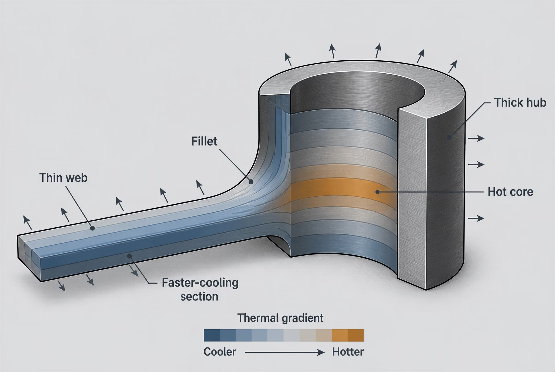
A thick region contains more thermal mass per unit surface area than a thin region. During heating, the thin section may reach the austenitizing temperature first, while the thick section remains cooler at its core. During quenching, the sequence reverses in a different way: the thin region loses heat rapidly, while the thick region retains heat and may continue transforming after the thin region has already hardened. Their temperature histories, transformation times, martensite fractions, and local volume changes can consequently differ.
An abrupt shoulder between a 40 mm boss and a 10 mm web is a classic restraint zone. The web may contract while the boss is still hot and dimensionally expanded. Later, the boss contracts and may pull the web into a different shape. If the thicker region transforms later, its expansion or contraction can alter the stress state established during the first stage of cooling. The result may be local yielding, a residual-stress concentration, or a dimensional change that is not predicted by a simple allowance for uniform quench shrinkage.
Design should favor gradual transitions: generous fillets, tapered webs, blended bosses, and more nearly uniform wall thickness. A gradual change does not eliminate thermal gradients, but it spreads them over a greater distance and reduces the sharp restraint imposed at one section boundary. Where a heavy section cannot be avoided, the drawing should identify the transition as a heat-treatment feature, not merely as a machining detail. Heating and quenching simulations can then examine the local temperature and phase-transformation history instead of treating the component as a uniform block.
The same principle applies to carburized, nitrided, and induction-hardened parts. A hard case over a soft or slowly cooling core creates another thickness-related mismatch. Surface and case hardening alter the location and magnitude of residual stress, as discussed in Parts I and II of the International Journal of Materials and Product Technology study. Final grinding can also release or redistribute these stresses. The National Institute of Standards and Technology materials-data archive, in Metallurgy of Heat Treatment, notes that unrelieved quenching stresses may cause warpage during machining because removing material changes the residual-stress balance.
Designers should therefore leave machining stock with restraint in mind, support thin regions during treatment where practicable, and specify intermediate stress relief or tempering when the process sequence requires it. Stock is not a guarantee against movement. It simply allows controlled correction after the principal stress-generating operations.
Symmetry, imbalance, and warpage modes
A geometrically symmetric part tends to develop more balanced thermal and transformation strains. Symmetry does not ensure zero distortion, because quench flow, fixturing, loading, and material history can break the balance. It does, however, remove one major source of unequal restraint. An asymmetric component cools at different rates on opposite sides, and one side may transform earlier or reach a different martensite, bainite, or retained-austenite condition. The unequal strain produces bending or torsion.
A flat plate with one heavy rib may bow toward or away from the rib as the two sides undergo different contraction histories. A shaft with an eccentric keyway can bend or twist because the keyed side has less mass and a different cooling surface area. A ring with uneven wall thickness may become oval rather than remaining circular. If the thermal and transformation differences vary along the length, the ring or shaft may also taper. These are typical modes, not universal results: the direction and magnitude depend on steel grade, hardenability, section dimensions, quench severity, agitation, orientation, and restraint.
Distortion modes
- Bow Curvature along a plate, bar, or shaft axis.
- Twist Angular rotation along the length.
- Ovality Loss of circularity in rings and cylindrical parts.
- Taper A progressive change in dimension along a length.
- Growth or shrinkage Dimensional change from transformation, thermal contraction, or stress release.
Common dimensional changes have distinct geometric expressions:
- Bow is curvature along a plate, bar, or shaft axis, often linked to unequal strain between opposite faces.
- Twist is angular rotation along the length, commonly promoted by asymmetric ribs, keys, slots, or uneven quench access.
- Ovality is loss of circularity in rings and cylindrical parts when circumferential cooling or transformation is uneven.
- Taper is a progressive change in dimension along a length caused by changing section, heat flow, or transformation history.
- Growth can accompany transformation or retained-austenite behavior, while shrinkage can result from thermal contraction, transformation strain, and machining stress release.
These modes can combine. A quenched gear may grow across one measurement direction, become slightly oval, and develop axial runout. Describing the part as having “quench distortion” is less useful than identifying the measured mode and relating it to the geometry that created unequal restraint.
ASM’s Basic Principles and Design Guidelines for Heat Treating of Steel places minimizing distortion and undesirable residual stress among the primary design criteria for heat treatment. That principle favors balanced cross-sections, centered features, uniform support, and quench access that is similar around the component. It also supports designing datum surfaces and inspection points around the anticipated distortion mode rather than assuming every dimension will move by the same amount.
Holes, edges, corners, and sharp section changes
A hole is not an empty detail from a heat-transfer standpoint. Its inner surface can cool from a direction different from the outer surface, while the material surrounding a small hole may have little thermal mass. A through-hole can also admit quenchant and create local flow differences. Blind holes behave differently because their ends may retain heat and restrict fluid movement. Closely spaced holes leave thin ligaments that cool and transform quickly, while the surrounding land remains hotter and more restrained.
Hole size, spacing, depth, and orientation should therefore be considered during heat-treatment design. Where dimensional accuracy is critical, avoid placing a small hole beside a heavy boss or a sharp internal shoulder unless the resulting local stress and distortion have been evaluated. A pattern of holes should be laid out as symmetrically as function permits. For carburized or nitrided components, the specified case depth and the untransformed core add another interaction between geometry and residual stress.
Edges and corners have a high surface-area-to-volume ratio and often cool sooner than broad faces. A sharp outside corner may develop a steep temperature gradient from the edge into the interior. An inside corner can retain heat, restrict quench flow, and concentrate stress at the same time. The corner may therefore transform at a different time from either adjoining face. Sharp edges also have less material available to distribute strain, making local plastic deformation and cracking more likely under severe quenching.
Generous radii and chamfers reduce both thermal discontinuity and mechanical stress concentration. They should be proportioned with machining, fatigue, coating, and hardening requirements in mind; a radius that is adequate for machining may still be too small for a severe quench. The International Journal of Materials and Product Technology identifies nonuniform thermal gradients as a principal source of quench distortion, while Worcester Polytechnic Institute describes the phenomenon as coupled heat transfer, phase transformation, stress, strain, and microstructural change. Component design cannot separate those events. It can make their interaction less extreme. The U.S. Department of Energy and the University of Iowa likewise connect thermal and residual stresses in steel castings with distortion, cracking, rework, weld repair, dimensional errors, and reduced service performance. Casting history, including prior thermal cycles and local solidification conditions, must be included when final dimensions and residual stresses are predicted.
8. Residual-Stress Profiles After Quenching
Quenching does not leave a steel part with one residual-stress value. It leaves a three-dimensional stress field that varies from the surface to the core, around corners, along changes in section thickness, and near holes, keyways, fillets, and interrupted surfaces. The final profile results from competing thermal contraction, phase-transformation strain, elastic constraint, and local plastic flow. ASM International separates these contributions into thermal, transformation, and hardening residual stresses, although the mechanisms interact during the same heating and cooling cycle (ASM International).
Residual stress and distortion are related but not identical. A part may retain substantial stress while showing little dimensional change because opposing strains balance one another. Conversely, a modest stress field can produce noticeable warpage when machining, grinding, or service loading removes the constraint that had kept the original shape stable.

Surface and core stress patterns
| Cooling and transformation sequence | Possible final stress pattern | Important variables |
|---|---|---|
| Surface contracts first; core remains hot | Surface tension may develop early | Cooling gradient and high-temperature yielding |
| Core contracts or transforms later | Surface compression and core tension may remain | Transformation timing and restraint |
| Uneven cooling around a feature | Mixed local tensile and compressive regions | Geometry, fluid access, and section thickness |
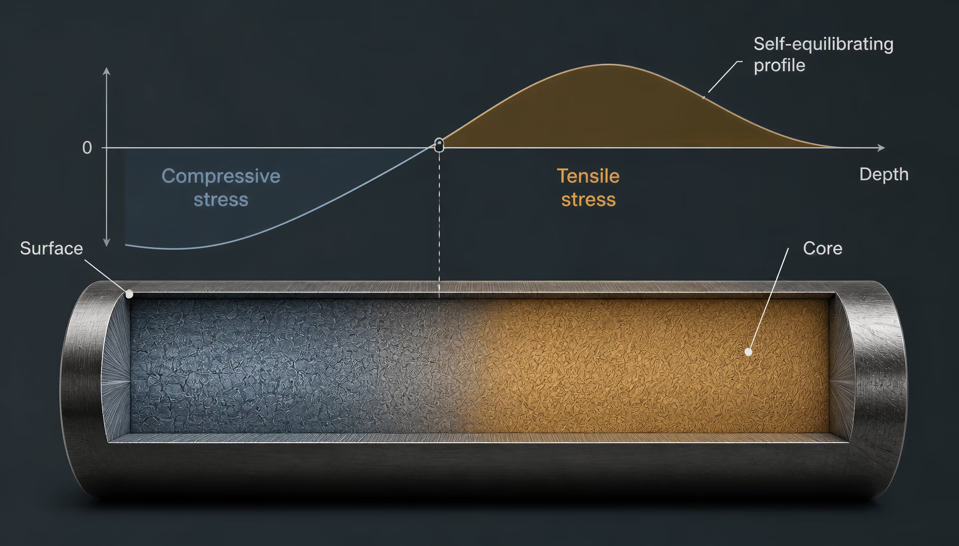
The familiar pattern of a quenched steel surface in compression and its core in tension is common, but it is not a universal rule. During the early stage of quenching, the surface cools and contracts while the hotter interior restrains that contraction. The surface can therefore enter tensile stress, sometimes beyond its yield strength, while the core is placed in compression. As cooling proceeds, the core contracts and may transform after the surface has already cooled substantially. The stress pattern can then reverse, leaving a compressive surface and tensile interior.
Martensitic transformation complicates this sequence. Austenite expands as it transforms to martensite, with the amount of expansion depending on carbon content, alloy composition, transformation temperature, and the fraction transformed. If the surface transforms first, its expansion is constrained by cooler or still-austenitic material beneath it. If the core transforms later, its expansion can alter the stress state already established at the surface. Bainite, pearlite, martensite, and retained austenite each contribute different transformation strains. A surface that cools quickly enough to form martensite may therefore have a different stress profile from a core that forms bainite or a mixed structure.
The location of tensile stress matters because surface tension is strongly associated with crack initiation, while compressive surface stress can delay opening of fatigue cracks. A tensile region may lie below a compressive surface layer, however, and a surface measurement will not reveal it. X-ray diffraction commonly samples only a shallow near-surface volume; the result describes that layer, not the complete component. Neutron diffraction, synchrotron methods, sectioning, hole-drilling, and modeled profiles can provide information at greater depth, but each method has its own resolution and assumptions.
Geometry changes the pattern. A thin web can cool and transform nearly through its thickness, whereas a thick hub, tooth root, or flange retains a hot interior for longer. Corners and edges lose heat through more than one surface and may transform earlier than adjacent material. A sharp transition in section thickness can therefore concentrate both thermal gradients and transformation mismatch. The 2005 International Journal of Materials and Product Technology discussion identifies nonuniform thermal gradients as a principal source of quench distortion (Part I).
Quenchant temperature, agitation, viscosity, wetting behavior, and local flow determine how rapidly heat leaves each surface. Oil, water, polymer solution, molten salt, and gas produce different heat-transfer histories. Even within one tank, an obstructed surface may cool more slowly than an exposed surface. The 2022 review in the Journal of Materials Engineering and Performance accordingly treats heat transfer, phase transformation, geometry, section thickness, quenchant selection, and quench severity as interacting variables rather than independent controls (2022 review).
Self-equilibrium and stress redistribution
A free component cannot retain a net unbalanced force or moment after cooling. Residual stresses must satisfy self-equilibrium across the part: tensile and compressive regions balance in force, and their distribution also balances bending moments. This does not mean that every local stress is small. It means that a high tensile layer requires compensating compression elsewhere, or that the complete three-dimensional field includes balancing stresses in another direction.
Removing material changes that balance. The Metallurgy of Heat Treatment text archived by the National Institute of Standards and Technology states that unrelieved quenching stresses can cause warpage during machining because material removal disrupts the residual-stress equilibrium (NIST materials-data archive). A ring may open after boring; a plate may bow after one face is milled; a hardened gear may move during final grinding. These are not new stresses created by the machine alone. They are the visible consequence of releasing an existing field.
Microscale plastic deformation is central to this redistribution. Grains and packets do not all transform at the same time or in the same way. Differences in crystallographic orientation, local carbon concentration, prior-austenite grain structure, and neighboring phase constrain create small plastic strains. The Part II article in the International Journal of Materials and Product Technology attributes residual stress in quenched steel partly to this microscale plastic deformation and connects the result with quenchant conditions, surface and case hardening, and final grinding (Part II). Tempering can reduce stress by allowing recovery and limited structural adjustment, but it does not guarantee a stress-free part.
Through-hardening versus surface and case hardening
Through-hardening tends to create a stress field across most or all of the section, provided the section is small enough and the steel has sufficient hardenability. A low-alloy grade such as AISI 1045 may form martensite near the surface while retaining softer transformation products toward the center in a thick section. A higher-hardenability grade such as AISI 4140 can transform more deeply under the same nominal quench, changing both the hardness profile and the transformation-strain distribution. The resulting residual-stress profile depends on the actual section, austenitizing practice, prior microstructure, and quench severity—not on grade designation alone.
Surface hardening creates a sharper material contrast. Induction hardening heats a surface layer rapidly, while carburizing enriches the near-surface austenite in carbon before quenching; nitriding forms a hard compound or diffusion layer without the same bulk transformation route as carburizing. In carburized steel, the high-carbon case may transform at a lower temperature and retain some austenite, while the lower-carbon core transforms differently. Case expansion, core restraint, retained austenite, and local plasticity can leave the case in compression, tension, or a mixed profile depending on timing and process conditions. Surface hardening is therefore not simply “hard outside, soft inside” from a stress perspective.
Quench uniformity is especially important for case-hardened gears, shafts, and bearing components. Unequal cooling around a circumference can produce asymmetric transformation strain and bending even when the case depth is nominally consistent. Final grinding may further alter the surface stress state through heat and mechanical action; excessive grinding can introduce tensile stress or release the compressive balance established during quenching.
ASM’s Basic Principles and Design Guidelines for Heat Treating of Steel identifies minimizing distortion and undesirable residual stresses as primary heat-treatment design criteria (ASM International). That criterion requires profile-based thinking. The U.S. Department of Energy links thermal and residual stresses in steel castings with distortion, cracking, rework, weld repair, dimensional errors, and reduced service performance (DOE report). Casting history, as emphasized in University of Iowa work, can also affect the starting structure and stress field. The Worcester Polytechnic Institute report therefore treats quench distortion as a coupled problem involving heat transfer, phase transformation, stress, strain, and microstructural evolution (WPI report). A surface reading is one observation. The component’s behavior belongs to the whole profile.
9. Tempering, Stress Relief, and Subsequent Heat Treatment
What tempering changes and what it cannot guarantee
Tempering is a controlled reheating treatment applied after hardening, usually below the lower critical temperature, . Its immediate purpose is to modify as-quenched martensite: carbon redistributes, transition carbides or cementite form, and the supersaturated martitic lattice loses part of its tetragonal distortion. With increasing tempering temperature and time, hardness generally falls while toughness and dimensional stability improve. The response depends on alloy chemistry, prior austenitizing practice, section size, quench rate, and the fraction of retained austenite.
Tempering therefore changes both mechanical properties and residual stress, but it is not a universal eraser of distortion. A part that leaves the quench bowed, twisted, or oval may remain that way after tempering. Tempering can relieve some elastic stress and permit limited plastic accommodation, yet it cannot reverse every shape change already produced by uneven cooling, transformation strain, or local yielding. A shaft with different martensite fractions at its surface and core may continue to change dimension during tempering; a carburized component may respond differently in its case and core; and retained austenite may transform during tempering or later service, producing additional volume change.
This distinction follows the ASM Handbook chapter Residual Stresses and Distortion in Quenched and Tempered Steels, which separates thermal, transformation, and hardening residual stresses while showing that they act together. The 2022 review by the authors of Residual Stress and Distortion during Quench Hardening of Steels: A Review in the Journal of Materials Engineering and Performance likewise treats heat transfer, phase transformation, geometry, section thickness, quenchant selection, and quench severity as interacting variables. Tempering cannot compensate for a poor quench pattern, an unsuitable fixture, or an abrupt section transition.
Subsequent thermal exposure can create fresh dimensional movement. A second temper, a stress-relief cycle, nitriding, carburizing, induction hardening, brazing, welding, or final grinding may alter the temperature field and the balance of phases. Martensite may temper further, retained austenite may transform, and carbide precipitation may change local volume and yield strength. The final dimension is consequently a process-history result, not simply the dimension measured after quenching.
Thermal stress relief
Thermal stress relief reduces residual stress by heating the steel to a temperature at which local plastic flow and time-dependent relaxation can occur without intentionally austenitizing the entire part. The selected temperature must remain compatible with the required hardness, toughness, case depth, dimensional tolerance, and metallurgical condition. A stress-relief cycle specified for normalized low-carbon steel cannot be transferred unchanged to a quenched-and-tempered tool, a carburized gear, or a nitrided component.
Metallurgy of Heat Treatment, preserved in the National Institute of Standards and Technology materials-data archive, identifies thermal treatment as one route for reducing residual stress and warns that unrelieved quenching stresses can cause warpage during machining. The mechanism is straightforward: heating lowers the yield strength, allowing locked-in stresses to relax through small plastic strains and creep-like flow. Cooling must then be controlled. If the part is heated unevenly, held for too little time, or cooled with a new surface-to-core temperature difference, the treatment can replace one stress pattern with another.
Stress relief also does not guarantee zero distortion. A heavily stressed ring may change roundness as the stress field relaxes, even though the treatment has reduced the driving force for later movement. A casting may respond according to its solidification history, section thickness, riser location, and previous weld repair. A U.S. Department of Energy report on steel castings connects heating and quenching stresses with distortion, cracking, rework, weld repair, dimensional error, and reduced service performance; University of Iowa work similarly emphasizes that casting history belongs in predictions of final dimensions and residual stress.
For that reason, thermal stress relief should be planned around the complete sequence. Rough machining before relief may remove stressed material and expose movement; relief before rough machining may reduce that risk, but the reheating cycle itself can produce dimensional change. Fine machining and grinding should follow the final metallurgical treatment whenever the tolerance requires it. Surface and case-hardened parts demand particular care because the case, transition zone, and core have different compositions, transformation temperatures, and restraint conditions.
Mechanical stress relief and straightening
Mechanical stress relief changes the shape or stress distribution by applying force rather than relying mainly on temperature. Press straightening, roll straightening, peening, sizing, coining, and controlled cold deformation can correct a measurable bend or runout. They work by pushing selected regions beyond their elastic limit so that elastic recovery and plastic strain leave the part closer to the required geometry.
That correction is not stress-free. Straightening redistributes residual stress and may introduce tensile stress on one side of a section, compressive stress on the other, or localized yielding near supports and contact points. In hardened steel, excessive force can cause cracking; in a high-strength martensitic structure, cold straightening may reduce fracture resistance. Hot straightening lowers the required force but adds a thermal cycle that can temper martensite, change retained austenite, or produce a new temperature gradient. The allowable method therefore depends on grade, hardness, section geometry, and inspection requirements.
Mechanical correction can also conceal an unstable part rather than solve the underlying cause. If machining later removes a stressed surface layer, the corrected component may spring back or move in a different direction. The NIST-hosted Metallurgy of Heat Treatment specifically describes machining warpage caused by disruption of the residual-stress balance. International Journal of Materials and Product Technology studies associate quenched-steel residual stress with microscale plastic deformation and with quenchant conditions, surface or case hardening, and final grinding.
A sound sequence is therefore to reduce avoidable stress during austenitizing and quenching, temper promptly, apply a compatible thermal stress-relief treatment when needed, then rough machine, measure, straighten only within a controlled procedure, and finish machine or grind after the final heat exposure. Worcester Polytechnic Institute describes quench distortion as a coupled problem involving heat transfer, phase transformation, stress, strain, and microstructural evolution. Straightening and stress relief must be assessed in that same sequence. They reduce risk when controlled; poorly controlled reheating, force application, or material removal can create the next dimensional change.
10. Machining, Grinding, and the Release of Hidden Stress
Heat treatment does not always leave a steel part with its final dimensions fixed. A quenched and tempered component may pass an initial inspection, then move during turning, milling, drilling, or grinding. The cutting operation has not necessarily created the original distortion. It may have exposed a residual-stress imbalance that was already present after heating, quenching, transformation, and tempering.
ASM International separates heat-treatment residual stress into thermal, transformation, and hardening contributions (ASM Handbook, Residual Stresses and Distortion in Quenched and Tempered Steels). These stresses coexist with dimensional changes caused by thermal contraction, phase transformation, and local plastic deformation. The 2022 Journal of Materials Engineering and Performance review describes the result as a coupled response involving heat transfer, phase transformation, geometry, section thickness, quenchant selection, and quench severity (2022 review). Machining occurs after that history, not on a stress-free blank.
Why machining can reveal heat-treatment distortion
A machined surface can look geometrically correct while the part still contains self-balancing internal stresses. One region may be in compression and another in tension, with the opposing forces and moments balancing across the whole component. The balance can remain stable until a cutter removes one of those regions.
This is the practical mechanism described in Metallurgy of Heat Treatment: unrelieved quenching stresses can cause warpage during machining because material removal disrupts the residual-stress balance (NIST materials-data archive). A plate with tensile stress near one face and compensating compression deeper inside may bend after the stressed surface is removed. A ring may become oval. A shaft may change straightness after an eccentric layer is cut away. The cutter has changed the force distribution, and the remaining metal deforms until a new equilibrium is reached.
The amount of movement depends on more than stress magnitude. Part length, wall thickness, symmetry, local stiffness, section transitions, and the orientation of the residual-stress field all matter. A thick flange can restrain movement that would be obvious in a thin web. A keyway or cross-hole can remove material from one side and introduce a bending moment. A carburized or nitrided case may have a different stress and hardness profile from the core, so cutting through the case changes both the mechanical balance and the local load path.
Heat-treatment history also matters. The 2022 review and the Worcester Polytechnic Institute report describe quench distortion as the coupled outcome of heat transfer, phase transformation, stress, strain, and microstructural evolution (WPI report). Two nominally identical parts can therefore respond differently if their prior forging, casting, cold working, grain structure, heating rate, or quench agitation differed. The U.S. Department of Energy reports that thermal and residual stresses in steel castings can contribute to distortion, cracking, rework, weld repair, dimensional errors, and reduced service performance (DOE report). Casting history is not erased by later machining.
Material removal and stress redistribution
Machining allowance provides room for this uncertainty, but it is not a guarantee against movement. The allowance must be considered alongside the expected stress profile and the order in which surfaces are exposed. Removing a large amount from one side of a heat-treated part can release bending or twisting; removing comparable amounts from opposing sides can reduce the net imbalance, although symmetry alone does not ensure dimensional stability.
For that reason, staged material removal is commonly treated as a dimensional-control concept rather than a universal recipe. Rough machining may remove most of the allowance while leaving enough stock for the part to respond and for a later operation to correct its position. An intermediate inspection can then identify movement before the final geometry is committed. If roughing reveals substantial bow or runout, continuing directly to the finished dimension may simply reproduce the error with less remaining correction capacity.
The datum strategy must follow the part’s functional geometry and its changing stress state. Establishing every operation from a surface that moved during roughing can transfer distortion into later features. Conversely, changing datums without controlling the relationship between them can create a different form of accumulated error. On a shaft, the chosen axis, bearing seats, and end faces may need to be related through inspection rather than assumed to remain fixed. On a plate, the reference face may need reassessment after roughing and stress relaxation.
Inspection after roughing is therefore part of the process logic, not merely a final quality check. Straightness, flatness, roundness, parallelism, runout, and critical feature locations can change between roughing, stress-relief treatment, semi-finishing, and finishing. ASM identifies “minimizing distortion and undesirable residual stresses” as a primary steel heat-treatment design criterion (ASM Basic Principles and Design Guidelines for Heat Treating of Steel); machining practice cannot compensate for every unsuitable heat-treatment condition.
A stress-relief operation may reduce movement, but its temperature and duration must be compatible with the steel grade, hardness requirement, tempering condition, and surface treatment. Mechanical stress relief can also alter dimensions. Neither method should be assumed to remove all residual stress.
Grinding stresses and surface integrity
Bulk residual stress Residual stress distributed through a significant depth or volume of a component, rather than confined to a shallow surface layer.
Grinding presents a separate problem because its effects are concentrated near the surface. Bulk residual stress refers to stress distributed through a substantial part of the section and capable of producing global bending, twisting, or shape change when material is removed. Grinding-induced stress is often a shallow surface effect produced by mechanical deformation and heat. The two can coexist, but they are not interchangeable.
The International Journal of Materials and Product Technology review attributes residual stresses in quenched steel to microscale plastic deformation and discusses the influence of quenchant conditions, surface and case hardening, and final grinding (Part I; Part II). Grinding can impose tensile stress through localized heating followed by rapid cooling, or compressive stress through severe mechanical rubbing and plastic flow. The sign and depth depend on wheel specification, contact conditions, coolant delivery, stock removal, and the steel’s hardness and microstructure.
Excessive grinding heat can damage the tempered condition, produce grinding burn, soften selected areas, or create rehardening and untempered martensite. These changes may not produce dramatic immediate warpage, yet they can reduce fatigue performance or cause later dimensional change. Surface cracks are especially dangerous where a tensile residual-stress layer combines with cyclic service loading.
Part II’s discussion of final grinding is central to dimensional control: the last operation removes little stock, but it determines the functional surface and can still alter its stress state. Final grinding should therefore be treated as a controlled finishing stage, with inspection of geometry and surface integrity afterward. A part that met size before grinding has not necessarily met its final condition. The final surface, the underlying heat-treated structure, and the stress field must be considered together.
11. Cracking, Rework, and Service Consequences
Heat treatment can leave a steel component with both a dimensional error and a stored stress field. These are related, but they are not the same thing. Distortion describes a change in shape or size; residual stress describes self-equilibrating stress remaining after the external thermal or mechanical load has been removed. A part may be visibly straight yet contain damaging tensile stress, while another may be warped but carry a residual-stress pattern that is not immediately crack-critical.
The distinction matters in steel castings because heating, cooling, solidification history, machining, welding, and service loading all alter the final condition. ASM International identifies thermal, transformation, and hardening residual stresses as separate contributors in quenched and tempered steels. The 2022 review by Totten and co-authors in the Journal of Materials Engineering and Performance likewise describes distortion as the result of interacting heat transfer, phase transformation, geometry, section thickness, quenchant selection, and quench severity. No single “quench stress” explains every failure.
When residual stress becomes a crack-driving force
Residual stress becomes a crack-driving force when tensile stress concentrates at a defect or sharp geometric feature and raises the local stress intensity or energy release rate. The stored stress does not need to be large across the entire component. A casting pore, oxide film, shrinkage cavity, nonmetallic inclusion, lack-of-fusion region, machining mark, keyway, or abrupt section change can amplify the local tensile field. Applied tensile loading then adds to it. A component that survives inspection and heat treatment may crack later when cyclic loading, vibration, pressure, or thermal cycling supplies the remaining driving force.
The same interaction applies to hydrogen-assisted cracking. Hydrogen can reduce cohesive strength and promote localized plasticity, while residual tensile stress helps open a crack or sustain its growth. High-strength martensitic steels, hardened surfaces, weld-affected regions, and electroplated or chemically exposed components are therefore sensitive to the combined condition, not to residual stress in isolation. A compressive surface layer may delay crack opening, but subsurface tensile stress, grinding damage, or a pre-existing defect can still control failure.
Temperature changes the balance. At elevated service temperature, stress relaxation and creep may reduce some residual stress, but thermal expansion differences can create new stresses, and oxidation or microstructural degradation can weaken the section. At low temperature, reduced toughness can make a defect more dangerous even if the residual stress has not increased. Transformation during service can also change volume and stiffness. The U.S. Department of Energy report on steel castings connects thermal and residual stresses generated during heating and quenching with cracking, distortion, rework, weld repair, and reduced service performance; its implication is practical: inspection and design must consider the stress-defect-service combination.
Residual stress can also become dangerous during finishing. Metallurgy of Heat Treatment, available through the National Institute of Standards and Technology materials-data archive, notes that unrelieved quenching stresses may cause warpage during machining because material removal disrupts the original stress balance. Removing one side of a section can release tensile or compressive stress unevenly. A crack may then appear at a newly exposed defect, but the machining operation did not necessarily create the original stress field.
Distortion, weld repair, and rework
Distortion commonly triggers rework before it causes fracture. A warped casting may fail a dimensional inspection, misalign with a mating part, exceed machining allowance, or produce an uneven sealing surface. Straightening, local heating, additional machining, shot peening, stress relief, or weld repair can follow. Each operation changes the thermal and mechanical history again.
Weld repair is not a neutral correction. Welding imposes a small, intense heat source beside relatively cold steel, producing a new thermal gradient, a heat-affected zone, contraction on cooling, and possibly hard, brittle microstructures. If the casting already contains quench stress, the repair weld can superimpose tensile stress on an area containing porosity, inclusions, shrinkage defects, or prior cracking. Hydrogen control, preheat, interpass temperature, filler-metal selection, post-weld heat treatment, and inspection consequently matter as much as the visible weld profile.
The Department of Energy findings and University of Iowa work on steel castings are important because they connect final dimensional accuracy to casting history. Solidification sequence, local section thickness, risering, cooling restraints, prior thermal cycles, and subsequent heat treatment affect both the initial stress field and the response to later processing. A prediction based only on the final quench cannot account for stresses inherited from casting. The Iowa report specifically emphasizes including casting history when predicting final dimensions and residual stresses.
Rework can expose a second problem: a component may be brought within drawing tolerance while retaining a poor stress condition. Heavy grinding can remove a compressive surface layer and uncover tensile material beneath it. Repeated local straightening can cause plastic strain and reduce fatigue margin. Conversely, controlled stress relief may reduce distortion risk, but excessive or poorly controlled heating can alter hardness, temper condition, carburized depth, nitrided layers, or dimensional fit. ASM’s Basic Principles and Design Guidelines for Heat Treating of Steel therefore treats minimizing distortion and undesirable residual stress as primary design criteria, not as inspection issues to be corrected at the end.
Dimensional change in service
A component need not crack to fail its function. Dimensional instability can change bearing preload, gear backlash, shaft alignment, valve clearance, seal compression, or contact pressure. In a precision assembly, a small movement may cause rubbing, leakage, uneven load sharing, or accelerated wear. The part remains structurally intact, yet its service performance falls.
Several mechanisms can produce that movement. Residual stress may relax during service, allowing elastic recovery or plastic redistribution. Retained austenite may transform to martensite, causing expansion; tempering may reduce martensitic volume and hardness; and thermal cycling may repeatedly expose differences between case and core. Carburized, nitrided, induction-hardened, and through-hardened sections do not respond identically because their gradients in composition, hardness, transformation temperature, and residual stress differ.
Final grinding can also matter after heat treatment. The International Journal of Materials and Product Technology studies identify nonuniform quench gradients as a principal source of distortion and relate residual stress to microscale plastic deformation, quenchant conditions, surface and case hardening, and final grinding. The Worcester Polytechnic Institute report presents the same problem as coupled heat transfer, phase transformation, stress, strain, and microstructural change. Service qualification must therefore address dimensional drift as well as crack initiation. A straight, crack-free part at shipment is not necessarily a stable part in operation.
12. Measuring Distortion and Residual Stress
Inspection after heat treatment should combine two different records: a dimensional map showing how the component moved, and a stress characterization showing what elastic or plastic imbalance remains inside it. Distortion is a change in shape or size. Residual stress is a self-equilibrating stress field that remains after external loads and temperature gradients have disappeared. They are coupled, but they are not interchangeable. A part can meet a dimensional tolerance while retaining tensile stress that later causes cracking, machining movement, or fatigue damage. Conversely, a visibly warped part may have undergone substantial transformation strain even after much of its residual stress has relaxed.
ASM International identifies thermal, transformation, and hardening residual stresses as distinct contributors in quenched and tempered steels. The 2022 review by the authors of Residual Stress and Distortion during Quench Hardening of Steels in the Journal of Materials Engineering and Performance describes the outcome as an interaction among heat transfer, phase transformation, geometry, section thickness, quenchant selection, and quench severity (doi:10.1007/s11665-022-06667-x). Measurement must therefore preserve enough information about the part and its thermal history to distinguish a local dimensional defect from a process-wide response.

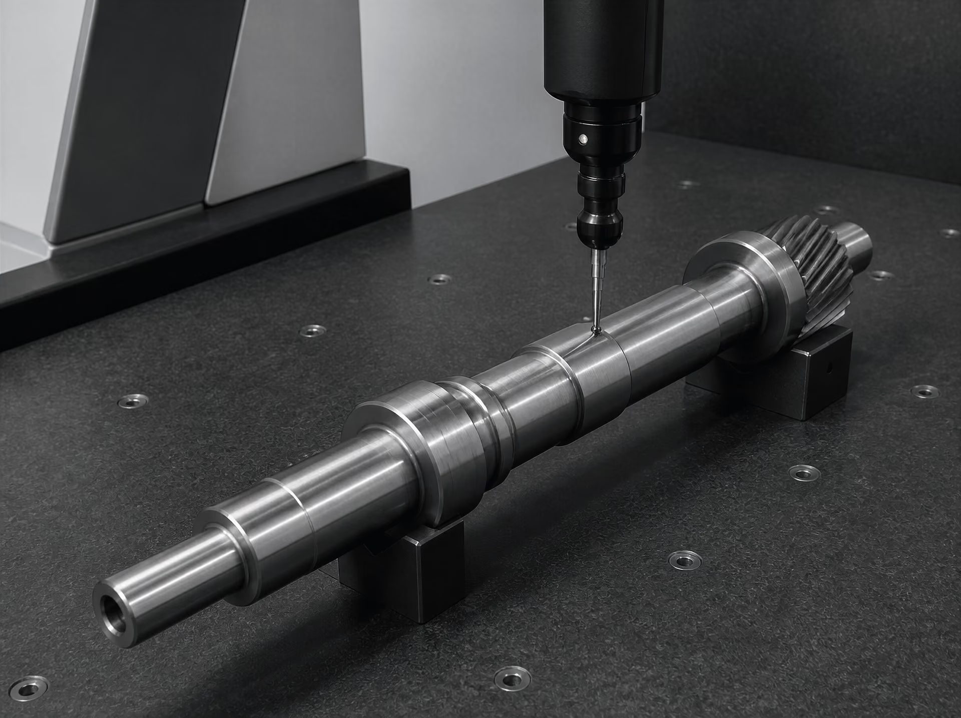
Dimensional inspection and datum selection
Inspection sequence
- Baseline Measure and record the untreated component, orientation, material condition, and datums.
- Post-treatment measurement Compare dimensions after quenching and tempering using the same reference strategy.
- Machining-stage measurement Inspect after roughing and after significant stock removal to identify stress release.
- Stress characterization Use a method whose depth and direction match the suspected stress gradient.
A meaningful dimensional inspection begins before heating. The untreated component should be measured, marked, and photographed, with its material condition and orientation recorded. A useful record includes the steel designation, lot or heat number, prior machining condition, surface treatment, fixture orientation, furnace cycle, transfer time, quenchant temperature and agitation, tempering cycle, and the time between treatment and inspection. The National Institute of Standards and Technology materials-data archive, in Metallurgy of Heat Treatment, warns that unrelieved quenching stresses can produce warpage during machining because removing material changes the residual-stress balance. A “before” record is therefore not optional when final grinding or rough machining follows quenching.
Datum selection controls the meaning of every later result. Datums should be tied to functional surfaces or stable geometric features, not simply to the most convenient edge. A large face may itself bow during quenching; using it as a perfect plane can hide that bow by forcing the coordinate system to follow the defect. For a shaft, the pre-treatment rotational axis, bearing journals, and a designated end face may define the reference frame. For a plate, a controlled plane and two orthogonal edges may be appropriate, provided those features are not expected to transform unevenly. Fixtures should constrain the component only enough to locate it. Excessive clamping during measurement can flatten a warped part and report the fixture condition rather than the free-state geometry.
Coordinate-measuring machines can map hole locations, profile deviation, parallelism, perpendicularity, flatness, and changes in axis position. A point cloud is more informative than a few maximum readings because it reveals whether distortion is global bending, local edge lift, ovality, twist, or a change concentrated around a thick-to-thin transition. The same coordinate system and probing strategy should be used before and after treatment. Temperature compensation matters: a steel component measured at different temperatures can show apparent dimensional change from thermal expansion alone.
Round parts require roundness and cylindricity checks at several axial stations. Measuring only one diameter can miss lobing or a bowed axis. Straightness should be checked along multiple generators and, where relevant, along the neutral or functional axis. A ring may retain its mean diameter while becoming oval; a gear may retain tooth-to-tooth spacing at one radius while its rim develops runout. Section-based comparison is useful for complex parts: compare transverse profiles through thin walls, hubs, ribs, fillets, and heavy sections, then compare matching sections before and after treatment. The pattern often points toward a thermal gradient or transformation mismatch.
Inspection should distinguish free-state distortion from distortion caused by release, cutting, or clamping. If a component is sectioned for metallography or stress measurement, its dimensions should be recorded before the cut and after each release step. A casting history may also matter. U.S. Department of Energy and University of Iowa reports connect heating and quenching stresses in steel castings with distortion, cracking, rework, weld repair, dimensional error, and reduced service performance; the Iowa work specifically includes casting history when predicting final dimensions and stresses.
Residual-stress measurement methods
| Method | Sampling depth or character | Main limitation |
|---|---|---|
| X-ray diffraction | Near-surface lattice strain | Does not by itself describe the core stress field |
| Hole-drilling | Incremental shallow depth profile | Semi-destructive and model-dependent |
| Contour measurement or sectioning | Stress release through a cut | Destructive and sensitive to cutting effects |
| Neutron diffraction | Greater internal penetration | Requires specialized access and reference-lattice data |
X-ray diffraction (XRD) measures near-surface lattice strain by observing shifts in diffraction peaks. With suitable elastic constants and an appropriate diffraction plane, those strains are converted into stress. The method is generally surface-sensitive, so it is valuable for carburized layers, ground surfaces, and quenched skins but cannot by itself describe the stress field at the centre of a thick section. Surface roughness, crystallographic texture, retained austenite, decarburization, and the selected radiation can alter the result. Measurements should be taken at locations chosen from the dimensional map: convex and concave sides of a bend, near fillets, at thin and thick sections, and along both principal directions.
Hole-drilling is a semi-destructive method. A small hole is introduced incrementally while strain gauges or optical methods detect the local elastic relaxation. An inverse calculation estimates the original stress as a function of depth. It samples more deeply than ordinary XRD but remains a near-surface technique, and the calculation assumes a defined geometry, elastic response, and sufficiently known stress variation. A hole near an edge, fillet, weld repair, or steep hardness gradient may violate those assumptions. The hole itself also interrupts the part, so its location must be selected where the resulting damage is acceptable.
Contour measurement, sectioning, and related destructive methods reveal stress by allowing a constrained body to relax. In contour methods, a component is cut along a plane, the newly exposed surface is measured, and an elastic model reconstructs the normal stress that produced the displacement. Sectioning can expose bending and opening movements directly, but the cut releases a three-dimensional stress field and may require corrections for cutting distortion, plasticity, and measurement noise. These methods are powerful for thick sections and welds, yet they do not provide a non-destructive production check.
Neutron diffraction can measure lattice strain at substantially greater depths than XRD because neutrons penetrate many steels more deeply. It can map internal stresses through a section without cutting the component, subject to access, gauge-volume, texture, phase, and reference-lattice requirements. It is especially useful when surface measurements and machining response suggest a buried stress gradient. Results from neutron diffraction, XRD, and hole-drilling should not be expected to match at the same nominal location unless their sampled volumes and depths are comparable.
Separating process error from measurement error
A disagreement between two inspections does not automatically prove that the heat-treatment process changed. Measurement uncertainty must be estimated separately from process variation. Repeat the same measurement without moving the component, then remove and refit it and repeat again. The difference separates instrument repeatability from datum relocation and operator or fixturing effects. Calibrated artefacts, traceable temperature measurement, probe qualification, and a documented alignment routine establish whether the coordinate system is stable.
Surface condition is a frequent source of false interpretation. Scale, oxide, decarburized material, grinding burns, shot-peened layers, and roughness can affect both dimensional probing and diffraction. Measure before and after cleaning under a defined procedure, and record any stock removal. If grinding follows quenching, inspect the surface before grinding and after each significant machining stage. A change in runout after stock removal may be released residual stress rather than a new quench defect, while a change in XRD stress may reflect removal of a stressed case.
Symmetry supplies an important diagnostic. Equivalent points on opposite sides of a nominally symmetric component should be compared, but they should not be averaged blindly. A symmetric process should produce a symmetric result; a persistent one-sided difference may indicate uneven quenchant flow, fixture contact, furnace loading, or a pre-existing machining error. Stress gradients also make single-point readings unreliable. Map several depths, orientations, and geometric zones, then compare the pattern with hardness, microstructure, retained-austenite content, and the recorded thermal cycle. Worcester Polytechnic Institute describes quench distortion as a coupled problem involving heat transfer, phase transformation, stress, strain, and microstructural evolution. The inspection system has to be equally disciplined about separating those effects from errors introduced by the measurement itself.
13. Modeling and Simulation of Heat-Treatment Distortion
Heat-treatment simulation is not a quench-rate calculator with a distortion correction added afterward. A credible model predicts the coupled evolution of temperature, phase fractions, strain, stress, and geometry while the steel is heated, held, quenched, tempered, and sometimes machined. Distortion is the change in shape or dimensions; residual stress is the internal stress remaining after external loads and temperature gradients have disappeared. They are different results of the same process history. A part can have substantial residual stress with little visible distortion, or obvious warpage after stresses are released by machining.
ASM International identifies thermal, transformation, and hardening residual stresses as distinct contributors in quenched and tempered steels. Thermal stress arises from constrained expansion and contraction. Transformation stress develops when regions transform at different temperatures and change volume at different times. Hardening stress is associated with the mechanical response of the evolving microstructure, including changes in yield strength and plastic flow. A simulation that omits any one of these mechanisms may still produce a smooth temperature curve, but its predicted dimensions can be wrong.
Thermal, metallurgical, and mechanical coupling
The thermal field is the starting point, not the whole answer. The solver must calculate heat conduction through the steel, radiation and convection at exposed surfaces, contact conduction at fixtures, and heat removal into the quench fluid. Surface heat transfer is usually expressed through a temperature-dependent boundary condition or heat-transfer coefficient. That coefficient changes during boiling, nucleate boiling, transition boiling, and liquid or vapor convection. It also varies with agitation, part orientation, quenchant temperature, fluid chemistry, and local surface condition.
The 2022 review, “Residual Stress and Distortion during Quench Hardening of Steels,” in the Journal of Materials Engineering and Performance, stresses that heat transfer, phase transformation, geometry, section thickness, quenchant selection, and quench severity interact. A uniform bath temperature does not create a uniform cooling history if one face is shielded, a bore traps vapor, or a thick hub cools more slowly than a thin rim. The International Journal of Materials and Product Technology articles in Parts I and II likewise identify nonuniform thermal gradients as a principal source of quench distortion and connect residual stress with quenchant conditions, surface and case hardening, and final grinding.
The metallurgical model converts temperature and composition into phase evolution. Austenite may transform to ferrite, pearlite, bainite, martensite, or retained austenite, depending on the local cooling path and hardenability. Each transformation can produce a transformation strain, including a volumetric component and, in some models, an orientation-dependent component. The constitutive model then combines thermal strain, transformation strain, elastic strain, and plastic strain:
\[ \boldsymbol{\varepsilon}_{total}=\boldsymbol{\varepsilon}_{elastic} + \boldsymbol{\varepsilon}_{plastic} + \boldsymbol{\varepsilon}_{thermal} + \boldsymbol{\varepsilon}_{transformation}. \]
This decomposition is a modeling framework rather than a claim that the strains occur independently. They interact through the stress state and the temperature-dependent yield strength. A martensitic region may form while the surrounding austenite is still hot and compliant; later cooling can reverse the local stress pattern. Transformation-induced plasticity may also occur when stress assists transformation or transformation strain promotes plastic flow.
Mechanical coupling must therefore include temperature- and phase-dependent elastic modulus, yield stress, hardening behavior, Poisson’s ratio, transformation strain, and, where necessary, creep or viscoplastic response. Constraints from fixtures, press dies, cores, or neighboring sections need explicit representation. A free bar, a clamped ring, and a gear supported on a fixture do not have the same predicted distortion even if they share the same steel and quench bath.
Material data and transformation kinetics
Material data determines whether the simulation describes a particular grade or only a generic steel. Required inputs commonly include chemical composition, density, thermal conductivity, specific heat, emissivity, phase-transformation temperatures, latent heat, phase fractions, transformation kinetics, transformation strains, and mechanical properties for each relevant phase. Hardenability data, such as a Jominy profile or calibrated continuous-cooling-transformation behavior, can help establish whether a section forms martensite or a mixture of bainite and pearlite.
Kinetics must match the thermal cycle. Isothermal transformation data alone may not predict a continuously cooled forging or casting. Models based on time-temperature-transformation diagrams, continuous-cooling-transformation diagrams, Koistinen–Marburger-type martensite relations, or calibrated phase-field and finite-element routines each carry assumptions about nucleation, incubation, composition, and prior austenite grain structure. Carbon gradients from carburizing, nitrogen gradients from nitriding, and segregation from casting require spatially varying inputs rather than one composition assigned to every element.
The National Institute of Standards and Technology materials-data archive provides a useful source of heat-treatment background, but archive data still needs checking against the actual grade, section size, surface condition, and equipment. Published values may have been measured with different specimen geometries or cooling rates. A model calibrated for an oil quench should not be transferred untested to polymer solution, water, gas, or an interrupted quench. The quench boundary is part of the material-process data set.
Calibration should compare predicted temperatures, phase fractions, hardness, dimensions, and stresses with measurements from the specified process. Thermocouples, infrared measurements where practical, dilatometry, hardness traverses, metallographic phase counts, coordinate-measuring-machine scans, and X-ray or neutron diffraction can test different portions of the model. Distortion calibration should include multiple features: bore diameter, face flatness, runout, length, and angular change. Matching one final dimension can conceal compensating errors in heat transfer and transformation strain.
Mesh sensitivity matters because thin walls, sharp fillets, keyways, holes, case-depth transitions, and contact regions create steep gradients. Refining the mesh until the predicted final dimension changes only slightly is more meaningful than selecting a visually fine mesh once. Boundary assumptions deserve equal scrutiny. Perfectly symmetric cooling, perfectly rigid fixtures, constant heat-transfer coefficients, and frictionless supports can produce an orderly result that the furnace never creates. Sensitivity studies should vary mesh density, surface coefficients, fixture stiffness, friction, initial temperature, and phase-kinetic parameters to identify which uncertainties control the result.
Casting history and prediction of final dimensions
Casting history and prior processing can materially affect predicted final dimensions and residual stresses.Limited evidence
For cast steel, the initial condition is already a thermal and mechanical history. Solidification produces segregation, dendrite structure, porosity, residual stress, and nonuniform grain structure. Cooling after shakeout, riser removal, rough machining, weld repair, and stress relief can alter the stress field before hardening begins. The U.S. Department of Energy reports that thermal and residual stresses in steel castings can contribute to distortion, cracking, rework, weld repair, dimensional errors, and reduced service performance. A model that starts with a stress-free, compositionally uniform block at room temperature has discarded the evidence that controls much of the later response.
The University of Iowa report makes the same point in prediction terms: casting history must be included when estimating final dimensions and residual stresses. That can require a sequential workflow. A casting simulation first predicts solidification, cooling, shrinkage, and residual stress; the resulting temperature, phase, composition, and stress fields then become the starting state for austenitizing and quenching. Rough machining may be modeled next by removing elements or changing constraints, followed by another equilibrium calculation. This sequence captures stress redistribution that a single heat-treatment step cannot.
The final predicted geometry is consequently process-specific. It depends on furnace loading, austenitizing time, transfer delay, quench-fluid movement, fixture contact, tempering, cooling between operations, and material history. Simulation does not produce an abstract distortion value belonging to “steel” independently of those conditions. It predicts the response of a defined geometry, grade, starting state, equipment setup, and process schedule.
That distinction also explains why simulation should support process trials rather than replace measurement. The Worcester Polytechnic Institute report describes quench distortion as a coupled problem involving heat transfer, phase transformation, stress, strain, and microstructural change. The model is credible when it reproduces measured behavior across more than one part or condition, exposes the dominant sensitivities, and shows where residual stress will be released during machining. ASM’s heat-treatment design guidance therefore treats minimizing distortion and undesirable residual stress as primary design criteria, not as post-process corrections.
14. Process and Design Strategies for Controlling Distortion
Distortion control should be organized around reducing incompatible strain, not around promising zero dimensional change. During heating and quenching, different regions of a part expand, contract, transform, and yield at different times. ASM International identifies thermal, transformation, and hardening residual stresses as separate contributors, although they develop together in the actual component. The 2022 review in the Journal of Materials Engineering and Performance likewise describes quench distortion as an interaction among heat transfer, phase transformation, geometry, section thickness, quenchant selection, and quench severity.
A sound process therefore limits differences between neighboring regions. It does not merely select a faster quenchant or apply a larger machining allowance.
Designing for uniform heating and cooling
Geometry is the first process variable. Thick hubs connected to thin webs, abrupt shoulders, sharp keyways, blind holes, and unequal wall sections create different heating and cooling rates. They also produce local constraint: one region attempts to contract while another remains hot and expanded. The resulting stress may cause plastic deformation before martensite forms, or may be released later when residual stress is redistributed.
Simplifying the shape reduces these incompatibilities. Use gradual section transitions, generous fillets, and more nearly uniform wall thickness where the functional design permits. Avoid sudden changes in cross-section near bearing seats, gear teeth, or locating surfaces. A transition that is modest in the drawing can have a large effect during quenching because the thinner region may reach the martensite-start temperature while the thicker region is still undergoing thermal contraction. The International Journal of Materials and Product Technology identifies nonuniform thermal gradients during quenching as a principal source of quench distortion.
Heating must also be uniform through the load. Parts should be spaced so furnace atmosphere can circulate around them, rather than packed tightly in contact. Heavy baskets, stacked components, and shielded surfaces can delay heating locally. Preheating is useful when a large temperature difference would otherwise develop between the surface and core, especially for thick, complex, or highly alloyed parts. A staged cycle can reduce thermal shock, but preheating does not remove the need to control the austenitizing temperature and hold time. Excessive exposure can enlarge austenite grains, increase oxidation or decarburization, and alter the final transformation response.
Cooling uniformity matters as much as furnace uniformity. A quenchant should reach all relevant surfaces at a similar rate, with controlled temperature, agitation, and cleanliness. Vapour blankets, stagnant pockets, blocked passages, and uneven spray patterns create local cooling histories. The result may be a hard martensitic surface beside a region containing bainite, pearlite, or retained austenite, accompanied by different volume changes and different residual-stress states. Quench agitation should remove vapour and deliver repeatable heat transfer without forcing a thin feature to bend under fluid or handling loads.
Machining allowances should reflect this behavior. Critical datums can be left with sufficient material for finish operations after quenching and tempering, while unnecessary stock should not be added indiscriminately because it increases thermal mass and may increase section differences. The final grinding operation also deserves attention: the IJMPT study on quenched steel connects residual stress with quenchant conditions, surface and case hardening, and final grinding.
Choosing hardenability and quench conditions
Steel chemistry determines how quickly a section must cool to avoid diffusional products and obtain the required microstructure. Hardenability, not simply nominal hardness, should guide the choice. AISI 4140, for example, generally has greater hardenability than a plain-carbon steel of comparable carbon content because chromium and molybdenum delay transformation; AISI 52100 is selected for high-carbon bearing applications but requires close control of austenitizing and quenching because its carbide population and section size affect transformation behavior. The correct grade depends on the required hardness profile, toughness, wear resistance, dimensions, and service stresses.
Selecting a steel with adequate hardenability can permit a less severe quench. That reduces the temperature difference between the surface and core and lowers the thermal stress needed to produce the target structure. A very severe quench may produce high surface hardness, but it can also increase distortion, cracking risk, and residual stress without improving the required core properties. Conversely, insufficient severity can leave soft zones or excessive bainite and pearlite. The decision is a metallurgical compromise, not a general preference for oil, water, polymer, gas, or salt.
Quenchant concentration, temperature, movement, and maintenance must be specified as process variables. Polymer solutions can change cooling behavior as concentration and agitation change; oil viscosity and temperature affect circulation and heat transfer; gas quenching depends on pressure, velocity, and part exposure. Salt or staged quenching may reduce the temperature range over which severe thermal gradients develop, but the cycle must still provide the required transformation. The 2022 JMEP review stresses that quenchant selection and quench severity cannot be separated from geometry and section thickness.
Surface and case-hardening routes require particular care. Carburizing changes near-surface carbon content and therefore transformation temperature, hardenability, and volume change. Nitriding produces a hardened compound or diffusion zone with much less bulk transformation than carburizing, but distortion can still arise from prior machining stress, heating, fixture restraint, and post-treatment grinding. Vacuum heat treatment can improve atmosphere control, yet it does not automatically produce uniform cooling if load arrangement or gas flow is poor.
Tempering should follow quenching within the specified process window. It reduces the risk that untempered martensite and quenching stress will remain available for later cracking or warpage. Where residual stress remains unacceptable, mechanical or thermal stress relief may be appropriate, provided the treatment does not compromise hardness, case depth, dimensional tolerances, or surface condition. ASM’s heat-treatment design guidance identifies minimizing distortion and undesirable residual stress as primary design criteria.
Fixtures, orientation, and process sequencing
Fixtures should restrain movement without imposing a new, concentrated load path. Rigid clamping of a part that is trying to contract can exchange free distortion for high residual stress, local yielding, or cracking. Supports should contact strong, nonfunctional regions where possible, and contact pressure should remain consistent as the part changes temperature. Thin rings, plates, and shafts may need mandrels, hanging fixtures, or guided supports, but the fixture must allow the intended thermal contraction rather than lock it completely.
Part orientation controls both gravity effects and quenchant access. Long shafts may be suspended vertically to limit sag, while flat plates may require orientation that prevents vapour pockets and allows both faces to cool similarly. Cavities, gear teeth, slots, and holes should face the flow in a way that avoids trapped vapour or stagnant fluid. Load orientation must be validated in the actual basket, because neighboring parts can shield surfaces and change local cooling rates.
Sequencing is equally important. Rough machine before heat treatment, retain controlled finishing stock, then perform finish machining or grinding after quenching and tempering when the residual-stress state is known. For large castings or forged parts, the Iowa technical report’s warning is significant: casting history affects final dimensions and residual stresses. Solidification structure, prior thermal cycles, weld repairs, and uneven stock can survive into heat treatment and alter the predicted response.
Stress relief before hardening may reduce machining and manufacturing stresses that would otherwise combine with quench stresses. A post-quench stress-relief operation can reduce warpage risk in suitable steels, but it is not a universal remedy. The NIST Metallurgy of Heat Treatment material records that unrelieved quenching stresses can cause warpage during machining when material removal disturbs the residual-stress balance. Thus, the process plan should measure critical dimensions after each major operation, not only at final inspection.
The correct combination of geometry, steel chemistry, hardenability, section size, required microstructure, quenchant, fixture, orientation, and stress-relief schedule must be established for the specific component and equipment. Modeling can help connect heat transfer, phase transformation, stress, strain, and microstructural evolution, as described by Worcester Polytechnic Institute, but plant trials and dimensional measurement remain necessary because load arrangement and material history often decide whether the predicted strain is compatible in practice.
15. Grade, Standard, and Process-Specification Considerations
Why grade designation alone does not predict distortion
A steel grade identifies composition and, in some standards, limits on mechanical properties, cleanliness, delivery condition, or hardenability. It does not prescribe the final shape of a component after heat treatment. Two parts made from the same grade can develop different dimensional changes because their geometry, section thickness, prior microstructure, and machining sequence are different.
A long, slender shaft, a thick hub, and a thin plate do not experience the same thermal history during quenching. Their surfaces cool at different rates from their cores, and corners, holes, keyways, and abrupt section changes concentrate thermal and transformation strains. A nominally uniform part can therefore contain tensile and compressive residual-stress regions that balance internally while still producing bending, ovality, or local movement when material is removed.
The material designation also does not state the steel's effective hardenability under a particular furnace and quench cycle. Alloy chemistry affects the time-temperature-transformation response, but so do austenite grain size, prior ferrite-pearlite or bainitic condition, segregation, carbide distribution, and prior cold work. A grade supplied in a normalized condition will not respond exactly like the same grade supplied quenched and tempered. Casting history may add porosity, segregation, and pre-existing stress; the University of Iowa technical work on steel castings stresses that this history must be included when predicting final dimensions and residual stresses.
The 2022 Journal of Materials Engineering and Performance review, “Residual Stress and Distortion during Quench Hardening of Steels: A Review,” describes the result as an interaction among heat transfer, phase transformation, geometry, section thickness, quenchant selection, and quench severity. That is the correct engineering frame. ASM International likewise separates thermal, transformation, and hardening residual stresses in its ASM Handbook discussion of quenched and tempered steels. These stresses are coupled to distortion: transformation strains can trigger plastic flow, while thermal gradients can alter when and where martensite, bainite, or pearlite forms.
A designation such as 42CrMo4 under EN 10083-3 or AISI 4140 under an applicable ASTM or SAE specification should therefore be recorded exactly as specified, but it should not be treated as a distortion guarantee. Informal names and trade labels can conceal differences in chemistry limits, product form, delivery condition, and required hardenability. The standard matters; so does the actual material certificate.
Through-hardening and case-hardening specifications
A through-hardening requirement should state more than “harden and temper.” It should identify the austenitizing temperature or permitted range, heating method, holding basis, transfer time, quenchant, agitation, quench temperature, tempering temperature, tempering time, and the required hardness or microstructure at defined locations. Section size must accompany the requirement because a hardness target measured near the surface says little about the center of a large section.
A high-carbon or alloy steel may form martensite through a small section but only a mixed structure at the center of a thick section. That difference changes both volume change and stress development. A quench severe enough to meet the core hardness target may increase surface-to-core temperature gradients, cracking risk, and distortion. A milder or interrupted quench may reduce gradients but fail the specified transformation range. The specification must address that trade-off rather than assigning responsibility to the grade name.
Case hardening introduces additional variables. Carburizing, carbonitriding, nitriding, and induction hardening produce a hardened layer over a different core structure, so the case depth, surface carbon or nitrogen condition, retained-austenite limit, core hardness, and transition profile should be specified. Surface and case hardening are identified in the International Journal of Materials and Product Technology literature as contributors to residual stress, alongside quenchant conditions and final grinding. A carburized gear can distort through case transformation, core transformation, tooth geometry, and carburizing-related thermal exposure even when its bulk grade is unchanged.
For induction or flame hardening, frequency, power density, scan speed, overlap, spray arrangement, and starting temperature can alter the heated zone and transformation sequence. For nitriding, the compound-layer requirement and diffusion-zone hardness may control dimensional growth differently from a martensitic case. Retained austenite also matters: later transformation during service, tempering, grinding, or storage can change dimensions after the initial quench.
ASM's heat-treatment design guidance identifies minimizing distortion and undesirable residual stress as primary design criteria, not as inspection issues to be addressed only after processing. The 2005 IJMPT discussion of nonuniform thermal gradients identifies them as a principal source of quench distortion. Geometry, fixturing, load arrangement, quenchant movement, and part orientation must consequently appear in the process specification when they affect cooling uniformity.
Recording the complete heat-treatment condition
A useful record connects the material specification to the actual thermal and mechanical history. At minimum, it should identify the standard and grade designation, product form, heat or cast number, supply condition, section size, and any stated hardenability requirement. It should then record the complete cycle: furnace type and atmosphere, loading arrangement, preheat stages, austenitizing temperature, time at temperature, transfer delay, quenchant identity and concentration, bath temperature, agitation or flow, interruption method, and tempering schedule.
The record should also define what success means. Hardness locations, core and surface microstructure, case depth, retained-austenite limit, straightness, roundness, runout, flatness, and allowable dimensional change should be measurable against stated criteria. Before-and-after inspection should use the same datums where possible, because changing datums can confuse heat-treatment movement with machining error.
Machining sequence belongs in the record. Metallurgy of Heat Treatment, archived by the National Institute of Standards and Technology, notes that unrelieved quenching stresses can cause warpage when machining removes material and disrupts the residual-stress balance. Rough machining before hardening, stress relief between operations, stock allowance for grinding, and final grinding direction can therefore change the observed result without any change in steel grade or quench recipe.
The U.S. Department of Energy reports that heating and quenching stresses in steel castings can contribute to distortion, cracking, rework, weld repair, dimensional errors, and reduced service performance. A Worcester Polytechnic Institute report similarly treats quench distortion as a coupled problem involving heat transfer, transformation, stress, strain, and microstructural evolution. Process records should preserve enough information to compare those variables from one load to the next. A grade certificate alone cannot do that.
16. A Diagnostic Framework for Distortion Failures
A distortion failure should be treated as a process-history problem, not as proof that the quenchant was too severe. The part’s final shape records several events at once: heating, thermal expansion, phase transformation, plastic strain, quenching, tempering, machining, and sometimes grinding. Residual stress and distortion are coupled, but they are not identical. A part can meet its dimensional limit while retaining a dangerous tensile stress, or it can warp after machining when the cutting operation releases a stress balance that had remained hidden.
The first task is to define the defect with measurements. Record the amount and direction of bow, the angular change associated with twist, the dimensional change between datum features, and the location and orientation of any crack. A straightedge description such as “the shaft bent” is inadequate. Measure runout at several stations, map flatness across the full surface, and identify whether the error is symmetric about the part centerline. Compare the as-quenched, tempered, rough-machined, and finish-ground conditions where those records exist. The sequence often shows when the defect appeared.
Classifying bow, twist, growth, and cracking
Bow is a curvature error, commonly produced when one side of a plate, shaft, tooth, or beam experiences a different thermal or transformation strain from the opposite side. A large diameter-to-thickness difference, an offset hole pattern, an uneven case depth, or contact with a fixture can make that imbalance directional. Bow that reverses when the part is turned over may reflect measurement support or gravity; bow that follows the same material feature in every orientation is more likely metallurgical or geometric.
Twist is different. It indicates a variation in strain around the longitudinal or circumferential direction. Helical distortion in a shaft may arise from asymmetric quench flow, interrupted contact with a fixture, nonuniform carburized depth, or torsional stress released during transformation. A part with keyways, gear teeth, splines, or unequal wall thicknesses is especially sensitive because its mass distribution changes the local cooling rate.
Growth or shrinkage must be separated into thermal, transformation, and machining components. Austenite formation generally changes volume differently from the subsequent formation of martensite, bainite, or pearlite, and the net dimensional change depends on carbon content, alloy chemistry, cooling rate, and retained austenite. A carburized SAE 8620 gear therefore cannot be assessed by the same dimensional expectation as a through-hardened AISI 4140 shaft. The relevant result is not merely “larger” or “smaller,” but the change in each controlled dimension and its relation to the microstructure.
Cracking is a separate failure class, although the same stresses that cause warpage can contribute to it. Quench cracks often follow stress concentrations, sharp corners, keyways, grinding burns, or regions with high hardness and low toughness. Intergranular or network cracking may point toward overheating, excessive grain growth, carburizing damage, or embrittlement rather than quench severity alone. Record crack origin, orientation, depth, and whether it is associated with decarburization, retained austenite, carbides, or grinding damage. Magnetic particle inspection, penetrant inspection, metallographic sections, and fracture examination should answer different parts of that question.
Tracing the thermal and transformation history
After defining the defect, map it against geometry and mass distribution. Mark thin walls, bosses, ribs, holes, teeth, blind cavities, sharp transitions, and heavy sections. These features govern heat flow and can produce local differences in the start and finish of transformation. The 2022 review by the authors of Residual Stress and Distortion during Quench Hardening of Steels: A Review in the Journal of Materials Engineering and Performance describes heat transfer, phase transformation, geometry, section thickness, quenchant selection, and quench severity as interacting variables. That interaction should guide the investigation.
Review the furnace record before changing the quench. Confirm charge temperature, soak time, atmosphere potential, furnace uniformity, thermocouple location, load mass, tray arrangement, and spacing between parts. A furnace may meet its empty-chamber uniformity requirement while a densely packed load develops substantial part-to-part and surface-to-core temperature differences. Compare parts at the top, center, and edge of the load. If only one position produces the defect, the evidence points toward loading or flow rather than a universal material response.
Then reconstruct the quench. Record transfer time, bath or polymer temperature, agitation or nozzle movement, immersion orientation, part spacing, and whether vapor blankets or trapped pockets could have formed. The International Journal of Materials and Product Technology identifies nonuniform thermal gradients as a principal source of quench distortion, while its companion discussion links residual stress to quenchant conditions, surface and case hardening, and final grinding. Cooling curves or instrumented witness parts can show whether the surface cooled rapidly while the core remained hot, or whether one side received more effective heat transfer.
Verify the result metallurgically. Hardness traverses should include the surface, subsurface, and core where section size permits. Examine prior-austenite grain size, martensite or bainite distribution, retained austenite, carbides, decarburization, case depth, and any soft bands. A hardness value within specification does not prove that transformation occurred uniformly. For a carburized gear, for example, measure case depth at several teeth and around the circumference rather than relying on one section.
Residual-stress measurement is justified when dimensional release, cracking, fatigue performance, or repeated machining movement cannot be explained by geometry and hardness alone. X-ray diffraction can characterize near-surface stress; hole-drilling gives a shallow depth profile; neutron or synchrotron methods can examine deeper regions when available. Interpret every result with its measurement depth and direction. A compressive surface value does not rule out tensile stress below the case or at a transition.
Corrective action without changing one variable blindly
Compare multiple failed and successful parts, not just one spectacular failure. Match each part to its furnace position, heat number, prior machining route, quench batch, tempering cycle, and inspection result. Review steelmaking and casting history when relevant: segregation, porosity, prior forging reduction, weld repair, or uneven stock removal can influence both heat flow and the residual-stress field. The U.S. Department of Energy and University of Iowa reports on steel castings connect heating and quenching stresses with distortion, cracking, rework, weld repair, and service performance, and stress that casting history belongs in dimensional predictions.
Corrective action should change a controlled set of variables while preserving a comparison group. Possible measures include improving load symmetry, adding supports that do not restrain transformation, changing part orientation, refining austenitizing practice, applying a suitable preheat, modifying agitation or quenchant temperature, adding an interrupted quench, or changing the tempering schedule. No option should be selected from distortion data alone; hardness, microstructure, crack inspection, and residual stress must be checked afterward.
Changing quenchant severity alone can trade bow for cracking, or reduce one dimensional error while increasing retained austenite and later growth. Slower cooling may reduce thermal gradients but permit softer transformation products; faster cooling may improve hardenability response while increasing transformation stress. As the Worcester Polytechnic Institute report explains, quench distortion couples heat transfer, phase transformation, stress, strain, and microstructural evolution. The sound diagnosis therefore follows the entire chain, then changes the process where the evidence identifies the controlling imbalance.
17. Key Distinctions and Common Misconceptions
Heat-treatment distortion and residual stress are related, but they are not interchangeable descriptions of the same condition. A part may show little measurable shape change while retaining substantial internal stress, or it may distort after machining even though the original stress was not visible at the surface. The correct assessment follows the sources of strain: thermal gradients, phase transformations, plastic deformation, geometry, section thickness, material history, and the quench process.
ASM International’s Residual Stresses and Distortion in Quenched and Tempered Steels identifies thermal, transformation, and hardening residual stresses as distinct contributors. The 2022 review “Residual Stress and Distortion during Quench Hardening of Steels,” published in the Journal of Materials Engineering and Performance, likewise treats heat transfer, phase transformation, geometry, section thickness, quenchant selection, and quench severity as interacting variables rather than isolated causes.
Distortion is not synonymous with residual stress
Distortion is a change in a part’s dimensions or geometry: a shaft bends, a ring becomes oval, a plate develops dish-shaped warpage, or a hole moves from its intended position. Residual stress is an internal stress field remaining after external loads and temperature differences have been removed. It can be tensile in one region and compressive in another, balancing across the component without producing an obvious change in overall dimensions.
The two conditions become coupled when residual stress causes plastic strain. During quenching, the surface cools and contracts before the hotter core can contract with it. If the local stress exceeds the temperature-dependent yield strength, permanent deformation remains. Later, martensitic transformation changes the balance again because martensite occupies more volume than the parent austenite. A part can therefore leave the quench with both a changed shape and a self-equilibrated stress field.
A hardness result does not resolve this distinction. A carburized AISI 8620 gear may meet its specified surface hardness while retaining a bending error, retained austenite, or a harmful subsurface stress gradient. An AISI 4140 shaft may attain the required hardness after oil quenching and tempering yet move when a keyway or allowance is machined away. Metallurgy of Heat Treatment, preserved in the National Institute of Standards and Technology materials-data archive, specifically describes warpage during machining when material removal disrupts the residual-stress balance.
Surface X-ray diffraction or hole-drilling measurements also have limits. They describe a near-surface region, not automatically the stress state through the core. Neutron diffraction, contour methods, sectioning, or validated process models may be needed when a thick forging, casting, or carburized component has a steep stress gradient. The measured surface value can even have the opposite sign from the core value.
Quenching is not the only source of dimensional change
Quenching often receives blame because its temperature changes are rapid, but dimensional change begins before the part enters the quenchant. Heating can release machining stresses, alter carbide distributions, and produce nonuniform expansion. A casting may already contain residual stress from solidification, uneven cooling, hot spots, risers, weld repairs, or rough machining. The U.S. Department of Energy and University of Iowa reports on steel castings connect these thermal and residual stresses with distortion, cracking, rework, weld repair, dimensional errors, and reduced service performance. Casting history must therefore enter any prediction of final dimensions.
Transformation strain is not limited to martensite. Pearlite, bainite, ferrite, and martensite form over different temperature ranges and have different specific volumes. Transformation plasticity can occur when a phase change proceeds under stress, allowing deformation at stresses below the ordinary yield strength. Retained austenite can later transform during tempering, refrigeration, service loading, or grinding heat, causing additional expansion or local shape change. In carburized steels such as AISI 52100 or AISI 8620, the carbon gradient changes hardenability, transformation temperatures, martensite volume fraction, and retained-austenite content from surface to core.
Geometry controls how these effects develop. A thin web cools quickly, while a heavy hub remains hot; a sharp corner concentrates heat flow and stress; a bore changes the cooling area and constraint around the section. Quench severity and uniformity matter, but so do quenchant temperature, movement, agitation, part orientation, loading density, and vapor-film behavior. The 2022 Journal of Materials Engineering and Performance review describes these interactions directly. The Worcester Polytechnic Institute report presents quench distortion as a coupled problem involving heat transfer, phase transformation, stress, strain, and microstructural evolution.
Machining and grinding can add a later stage of dimensional change. Unequal stock removal exposes or redistributes stress, while grinding can create a shallow thermally affected layer and transformation-related stress if heat is not controlled. The International Journal of Materials and Product Technology Parts I and II identify nonuniform thermal gradients as a principal source of quench distortion and discuss quenchant conditions, surface and case hardening, retained austenite, and final grinding.
Stress relief does not guarantee dimensional stability
Tempering reduces some quenching stresses and changes the martensitic structure, but it does not erase every stress component or guarantee that dimensions will remain fixed. The result depends on tempering temperature, time, heating and cooling uniformity, section thickness, alloy chemistry, prior transformation, and the amount of retained austenite. A low-temperature temper may leave substantial stress; a higher-temperature treatment may trigger additional recovery, carbide precipitation, or transformation of unstable austenite.
Mechanical stress relief has a similar limitation. Vibratory treatment, stretching, or controlled thermal cycling can redistribute stress without correcting an unsuitable geometry, an uneven microstructure, or a casting defect. Stress relief may also reveal movement that was previously restrained.
ASM International’s Basic Principles and Design Guidelines for Heat Treating of Steel identifies minimizing distortion and undesirable residual stresses as primary design criteria, not as outcomes that automatically follow from meeting hardness. Dimensional stability requires process control and verification: measure before and after heat treatment, inspect critical form features, account for machining sequence, examine retained austenite where relevant, and select stress measurements that represent the part’s depth and geometry. A hardness profile is useful evidence of transformation, but it is not evidence that the entire stress field or final shape is acceptable.
18. Reference Tables and Practical Checklist
Heat-treatment records should be read as a chain of causes, not as isolated furnace and quench values. ASM International separates thermal, transformation, and hardening residual stresses, while the 2022 Journal of Materials Engineering and Performance review describes heat transfer, phase transformation, geometry, section thickness, quenchant selection, and quench severity as interacting variables. A part may therefore meet a hardness target and still move during machining, grinding, or service.
Mechanism-to-symptom table
| Mechanism or condition | Likely observation | What to check before assigning cause |
|---|---|---|
| Unequal surface cooling, interrupted agitation, or different local section thickness | Bowing, twist, ovality, taper, or nonuniform warpage after quenching | Part orientation, rack loading, quenchant flow, vapor-film behavior, sharp transitions, holes, and thin-to-thick section changes |
| Thermal contraction occurring before the core has cooled | Tensile surface stress, compressive core stress, dimensional change, or localized yielding | Temperature history through the section, heat-transfer coefficients, and whether the part was restrained |
| Transformation strain from austenite-to-martensite, bainite, or pearlite formation | Growth, shrinkage, bore-size change, length change, or shape change that does not follow thermal contraction alone | Steel grade, carbon and alloy content, hardenability, transformation sequence, cooling rate, and transformation start temperatures |
| Different transformation times in the surface and core | Bending, distortion around shoulders, residual-stress gradients, or delayed movement during tempering | Section thickness, case depth, core microstructure, retained austenite, and temperature uniformity |
| High quench severity or excessive temperature difference | Quench cracks, corner cracks, grinding cracks, or sudden failure during inspection | Quenchant type, temperature, concentration, movement, transfer time, part cleanliness, and corner radii |
| Residual-stress redistribution during material removal | A machined face moves, a bore closes or opens, or a previously straight part bends | Material removed from each side, rough-machining allowance, stress-relief treatment, and the order of operations |
| Retained austenite transforming after quench | Delayed dimensional growth, hardness drift, or movement during tempering, subzero treatment, or service | Final quench temperature, alloy content, tempering schedule, retained-austenite measurement, and elapsed time |
| Localized grinding heat or excessive stock removal | Temper burn, tensile surface stress, grinding cracks, or dimensional taper | Wheel specification, dressing, coolant delivery, contact time, spark-out, and inspection for burn |
| Casting, forging, welding, or prior machining history | Distortion that varies between nominally identical parts | Starting microstructure, segregation, inclusions, prior stress relief, straightening, and material certificates |
This table is a diagnostic aid, not a substitute for metallography or a measured thermal history. Nonuniform cooling most directly points toward warpage, transformation strain toward growth or shape change, and residual-stress redistribution toward machining movement. Excessive thermal or transformation stress raises cracking risk, but cracking also depends on defects, geometry, surface condition, and the steel’s fracture sensitivity.
Process-record checklist
Process-record essentials
- Material Record the exact designation, product form, heat or cast number, chemistry, and prior condition.
- Geometry Record section thickness, transitions, holes, fillets, datums, and machining allowance.
- Heating Record furnace, load arrangement, atmosphere, preheat stages, ramp, and austenitizing condition.
- Quenching Record medium, temperature, concentration or viscosity, agitation, orientation, and transfer delay.
- Finishing Record tempering, machining stock removal, grinding conditions, and inspection stages.
Record the material condition before selecting a heat-treatment explanation. Identify the designation exactly as supplied, such as AISI 4140, ASTM A681 D2, or ASTM A295 52100, and record the applicable product standard, heat number, chemical analysis, prior annealed or normalized condition, grain size, segregation, inclusions, and prior cold work. A nominal grade alone is insufficient when comparing results from different suppliers or standards.
For geometry, preserve the drawing revision and measure overall dimensions, section thicknesses, length-to-diameter ratios, wall thickness, holes, keyways, threads, fillets, grooves, sharp corners, asymmetry, datum scheme, and machining allowance. Note whether the part was forged, rolled, cast, welded, or assembled before heat treatment. The University of Iowa technical report on steel castings shows why casting history must remain in a final-dimension and residual-stress assessment.
Heating records should include furnace identification, calibration status, load mass, loading pattern, support points, atmosphere or vacuum level, preheat stages, ramp rates, furnace recovery time, and part-temperature measurements where available. For austenitizing, record the target temperature, time at temperature, estimated or measured core equalization, carbon potential where applicable, atmosphere chemistry, surface condition, and whether carburizing, carbonitriding, nitriding, or vacuum processing preceded the quench.
Quenching records need more than the name of the medium. Record oil, water, polymer, brine, gas, or salt-bath composition; quenchant temperature; concentration or viscosity; agitation rate and direction; flow uniformity; transfer delay; load arrangement; immersion orientation; and any interruption or delay. The International Journal of Materials and Product Technology papers identify quenchant condition, quench severity, surface and case hardening, and final grinding as relevant to residual stress.
For tempering, record transfer time from quench, tempering temperature, duration at part temperature, number of cycles, furnace uniformity, cooling method, and any cryogenic or stabilization treatment. Measure hardness by location rather than relying only on one surface reading. Include dimensional measurements before heat treatment, after quench, after temper, after rough machining, after finish machining, and after grinding.
Machining records should identify datum changes, stock removed by operation, clamping forces, fixturing distortion, tool path, and the time between roughing and finishing. Grinding records should include wheel type, dressing interval, infeed, traverse speed, coolant, spark-out, and surface-temperature or burn checks. Inspection should cover hardness mapping, dimensional datums, straightness, roundness, runout, surface cracks, magnetic-particle or penetrant results, retained austenite where relevant, and residual-stress measurements when the risk justifies them.
Simulation inputs must state steel chemistry or grade, phase-transformation data, temperature-dependent properties, latent heat, elastic-plastic constitutive data, transformation strain, transformation kinetics, hardenability, initial microstructure, contact conditions, quenchant heat-transfer behavior, agitation, fixture restraint, mesh sensitivity, and the actual furnace and load geometry. A model that omits transformation strain can predict cooling while missing the principal source of shape change.
Questions for interpreting published data
Ask first what steel and product condition were tested. “Tool steel” may mean ASTM A681 D2, AISI H13, or another material with different hardenability and transformation behavior. Was the specimen a thin coupon, a ring, a gear, a casting, or a forged bar? Section thickness and geometry can change the temperature gradient enough to reverse the apparent effect of a quench setting.
Next ask whether the reported temperature is furnace temperature, surface temperature, or core temperature. Was quenchant agitation measured or merely described as “moderate”? Were concentration, viscosity, bath temperature, transfer time, and load arrangement controlled? Without those details, a numerical distortion value is not portable.
Check the measurement method and datum scheme. A reported change in length may include elastic springback, fixture release, retained-austenite transformation, or a measurement reference that differs from the production drawing. Determine whether the result was taken after quench, after tempering, after machining, or after grinding.
Finally, separate evidence from recommendation. A result in the 2022 review Residual Stress and Distortion during Quench Hardening of Steels supports coupled-process reasoning; it does not establish a universal quench severity or allowable distortion. No numerical distortion limit or universal process setting should be transferred between components without validating the steel grade, standard, geometry, equipment, and heat-treatment history.
Compact reference: nonuniform cooling → warpage; transformation strain → growth or shape change; residual-stress redistribution → machining movement; excessive thermal or transformation stress → cracking risk. These links are supported by ASM International, the 2022 Journal of Materials Engineering and Performance review, the Worcester Polytechnic Institute report on coupled heat transfer and microstructural change, the National Institute of Standards and Technology materials-data archive, and the International Journal of Materials and Product Technology studies.
References
- [1]Residual Stress and Distortion during Quench Hardening of Steels: A Review. Journal of Materials Engineering and Performance, 2022. https://doi.org/10.1007/s11665-022-06667-x
- [2]Residual Stresses in Quenched Steel: Parts I and II. International Journal of Materials and Product Technology, 2005. https://doi.org/10.1504/IJMPT.2005.007941; https://doi.org/10.1504/IJMPT.2005.007942
- [3]Distortion and Residual Stress. Worcester Polytechnic Institute report, 2021. https://bpb-us-w2.wpmucdn.com/wp.wpi.edu/dist/3/125/files/2021/06/Distortion-and-Residual-Stress.pdf
- [4]Metallurgy of Heat Treatment. National Institute of Standards and Technology materials-data archive. https://materialsdata.nist.gov/bitstream/handle/11115/189/Metallurgy%20of%20Heat%20Treatment.pdf