



What Heat Treatment Means in Steel
Heat treatment is a planned sequence of heating, holding, and cooling operations applied to steel so that its internal structure and resulting properties change in a controlled way. The furnace temperature is only one part of that sequence. The complete treatment includes the starting condition of the material, the rate at which it reaches temperature, the time spent at temperature, the surrounding atmosphere, the way heat moves through the section, and the path by which the steel cools.
What a treatment can change
- Structure Phase constitution, phase morphology, defect structure, and grain structure
- Mechanical response Hardness, strength, toughness, and ductility
- Manufacturing response Machinability, residual stress, and dimensional stability
- Surface performance A hard wear-resistant surface over a tougher core
That distinction separates metallurgical heat treatment from simply heating steel and letting it cool. A treatment may be designed to alter phase constitution, phase morphology, defect structure, hardness, strength, toughness, ductility, machinability, dimensional stability, or surface properties. It may also relieve residual stress, refine grains, prepare steel for machining, or produce a hard wear-resistant surface over a tougher core.[1] Steel Heat Treating—Fundamentals and Processes. ASM International. ASM Handbook Volume 4A, 2024.
ASM Handbook Volume 4A, Steel Heat Treating—Fundamentals and Processes, covers austenitizing, quenching, annealing, tempering, austempering, martempering, surface hardening, hardness, hardenability, distortion, and related processes (ASM International, 2024). Those subjects are connected by one principle: a steel’s response depends on its composition and thermal history together.

Thermal cycles and metallurgical change[2] Steel Metallurgy & Heat Treatment course outline. ASTM International. ASTM International course outline, 2024.
Steel contains phases whose stability changes with temperature and composition. Ferrite is a relatively soft body-centered cubic iron phase with limited carbon solubility. Austenite is face-centered cubic and can dissolve much more carbon. Cementite, or iron carbide, is hard and brittle. Depending on carbon content, cooling rate, and alloy additions, these constituents can form pearlite, bainite, or martensite. The ASTM International Steel Metallurgy & Heat Treatment course outline identifies ferrite, austenite, cementite, pearlite, martensite, and bainite as central phases and structures in steel processing (ASTM International, 2024).
During austenitizing, steel is heated into a temperature range where some or all of its original ferrite, pearlite, or cementite transforms to austenite. Holding allows carbon to dissolve and temperature differences to diminish, but excessive holding can enlarge austenite grains, increase oxidation, and worsen later toughness or distortion. The required temperature and time depend on grade, prior microstructure, section thickness, furnace circulation, and the desired transformation.
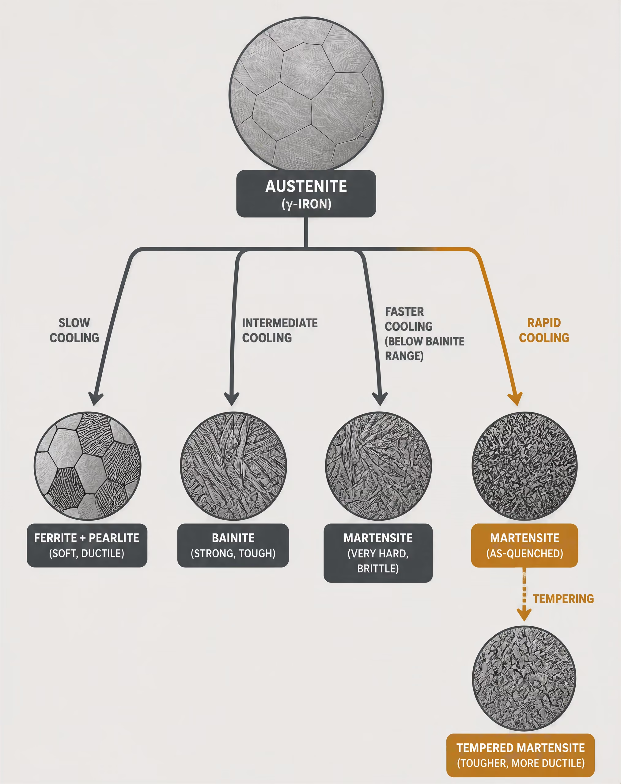
Cooling then determines what the austenite becomes. Slow cooling can permit diffusion-controlled formation of ferrite and pearlite. Intermediate cooling may produce bainite. Rapid cooling can suppress diffusion long enough for austenite to transform to martensite, a supersaturated and highly strained structure. Martensite provides high hardness, but untempered martensite can contain substantial residual stress and may be too brittle for service. Tempering reheats quenched steel below the austenite transformation range, allowing controlled carbon redistribution and reducing stress while changing hardness and toughness.
| Treatment | Typical cooling or transformation path | Primary purpose |
|---|---|---|
| Annealing | Slow furnace cooling | Softening, ductility, stress reduction, or machinability |
| Normalizing | Air cooling from the austenitic range | Finer, stronger structure than full annealing |
| Quenching and tempering | Rapid cooling followed by reheating below the austenite range | Balance of strength, hardness, and toughness |
| Austempering | Isothermal bainite formation | Controlled bainitic structure |
| Martempering | Temperature equalization before martensite forms | Reduced distortion risk |
The principal treatments therefore represent different thermal paths rather than interchangeable recipes. Annealing generally uses slow cooling to soften steel, improve ductility, reduce residual stress, or improve machinability. Normalizing uses air cooling from the austenitic range and often produces a finer, stronger structure than full annealing. Quenching followed by tempering seeks a selected balance of strength, hardness, and toughness. Austempering forms bainite through transformation at an intermediate temperature, while martempering reduces the temperature difference between the surface and core before martensite forms, lowering distortion risk without removing the need for tempering.
Flame hardening and induction hardening heat only a surface layer rapidly, then quench it. The result can be a martensitic case with a comparatively tough interior, but case depth, carbon content, geometry, power input, and quench timing must all be controlled. ISO 683-1:2016 specifies delivery requirements for non-alloy steels intended primarily for quenching and tempering, austempering, flame hardening, induction hardening, and, in some cases, normalized conditions. The standard does not make one cycle suitable for every grade or component.
Properties versus microstructure
Steel properties depend on microstructure and thermal history rather than furnace temperature alone. Strong evidence
Mechanical properties are consequences of structure, not direct consequences of furnace temperature. Two steels at the same nominal temperature can have different hardness or toughness because they contain different carbon levels, alloying elements, grain sizes, precipitates, inclusion populations, or residual stresses. Even within one grade, a forged bar, a cold-worked sheet, and a previously quenched-and-tempered part do not begin the treatment from the same metallurgical condition.
Hardenability The ability of a steel section to develop a hardened structure through its depth under specified austenitizing and cooling conditions; it is distinct from the maximum hardness attainable.
Key terms in composition and response
- Maximum hardness
- The greatest hardness obtainable when the relevant region becomes sufficiently martensitic; it is governed largely by carbon content.
- Hardenability
- The depth to which a steel can develop a hardened structure under a particular cooling condition.
- Retained austenite
- Austenite that remains after cooling below the martensite-finish temperature.
- Carbon equivalent
- A compositional index used to estimate transformation or weldability effects from carbon and alloying elements.
Carbon strongly affects the amount and hardness of martensite, while chromium, molybdenum, manganese, nickel, and other alloying elements alter transformation temperatures and delay diffusion-controlled reactions. Boron, when properly controlled, can increase hardenability in suitable steels. Hardenability is not the same as maximum hardness. Maximum hardness is governed largely by carbon content; hardenability describes how deeply a steel can develop a hardened structure under a particular cooling condition.
Microstructure also explains why hardness alone cannot define a successful treatment. A high hardness value may indicate martensite, but it does not reveal whether the part contains quench cracks, excessive retained austenite, coarse prior-austenite grains, or damaging tensile stresses. A lower hardness may be intentional where impact toughness, fatigue resistance, machinability, or dimensional stability matters more.
The iron–iron-carbide phase diagram describes equilibrium or near-equilibrium phase relationships. It helps identify transformation ranges and carbon solubility, but it does not predict the full result of a practical quench. Time-temperature-transformation diagrams describe transformations during isothermal holding; continuous-heating and continuous-cooling transformation diagrams describe paths more like those used in furnaces and production equipment. ASM’s 2024 treatment chapter specifically distinguishes these diagrams and addresses distortion and residual-stress control. The difference matters because transformations require time, and industrial cooling is rarely instantaneous or perfectly uniform.
Why temperature alone is not enough
A stated temperature such as 850 °C describes a furnace set point, not the complete thermal condition of a component. A thin 10 mm plate may reach that temperature quickly and uniformly. A large gear tooth, thick shaft, or weld repair may have a hot surface and a cooler core for a substantial part of the cycle. If the surface transforms or expands before the interior, stresses develop. Quenching can then add thermal contraction and transformation strain, producing distortion or cracking even when the furnace temperature was correct.
Heating rate changes the response as well. Rapid heating can leave a section thermally uneven and may bypass transformations that would occur during slower heating. It can also increase thermal stress. Slow heating may encourage unwanted grain growth or permit surface reactions before the target temperature is reached. Holding time must be long enough for the coldest region to reach the required condition, not merely long enough for the furnace display to show the set point.
Atmosphere is another control variable. Oxygen can produce scale and decarburization; carbon-bearing atmospheres can alter surface carbon potential. Either condition changes the surface hardness and dimensions even if the core receives the intended cycle. Salt baths, vacuum furnaces, protective gases, and air furnaces therefore produce different surface outcomes.
Cooling severity, agitation, quenchant temperature, part orientation, and geometry determine the actual cooling curve. Sharp corners cool differently from broad faces, and holes or thin webs can create local temperature gradients. Prior cold work, segregation, weld heat-affected zones, and earlier tempering also alter nucleation sites and transformation kinetics.[3] Fundamentals of the Heat Treating of Steel. ASM International. ASM technical monograph, 2024.[4] ISO 17663:2023. International Organization for Standardization. International standard, 2023.
ISO 17663:2023 places heat treatment associated with welding and allied processes within a quality-requirements framework covering work in workshops or on site, mainly for ferritic steels and related welded or formed components. That context is important: the thermal cycle must be specified, monitored, and verified, particularly where stress relief, hydrogen control, interpass heating, or local post-weld treatment affects service performance. Heat treatment is therefore a controlled history of the whole component—not a single number on a furnace controller.
Steel Composition and the Iron–Carbon System
Pure iron and carbon solubility
Steel heat treatment begins with a deceptively simple system: iron containing carbon. The simplicity ends when temperature, composition, and cooling rate are considered together. Pure iron changes crystal structure as temperature rises. Below 912 °C, it is primarily ferrite, or α-iron, with a body-centred cubic (BCC) lattice. Between 912 and 1394 °C, it becomes austenite, or γ-iron, with a face-centred cubic (FCC) lattice. From 1394 °C to its melting point near 1538 °C, it is δ-ferrite, another BCC form.
Carbon occupies interstitial sites in these lattices, but the available space differs sharply. Ferrite dissolves very little carbon: its maximum equilibrium solubility is about 0.022 wt% C at 727 °C, and its room-temperature solubility is closer to 0.008 wt% C. Austenite can contain far more, reaching approximately 2.14 wt% C at 1147 °C in the metastable iron–iron-carbide system. This difference is central to hardening. During austenitizing, carbon enters the FCC lattice and may also dissolve from cementite. If the austenite is then cooled rapidly enough, carbon cannot diffuse out in the ordinary way. The lattice changes toward BCC form, but the trapped carbon produces martensite, a supersaturated and highly strained phase.
Carbon therefore does more than increase hardness as a direct solute. It changes which phases are stable, the temperatures at which transformations begin, the amount of carbide that can form, and the response to cooling. At low concentrations, ferrite and pearlite may form readily during slow cooling. At higher concentrations, the balance shifts toward greater pearlite or cementite content. Under rapid cooling, the same carbon may remain in martensite instead.
The carbon content of a nominal grade is not the whole thermal history. Section thickness, prior grain size, heating rate, austenitizing temperature, holding time, quench medium, surface condition, and temperature uniformity can change the resulting microstructure. ASM International’s 2024 treatment of steel fundamentals places the iron–carbon system beside austenitizing, transformation diagrams, hardness, hardenability, quenching, tempering, and residual-stress control for this reason: composition supplies the possibilities, while the thermal cycle selects among them.
The iron–iron-carbide phase diagram
| Diagram | Thermal path represented | Primary use |
|---|---|---|
| Iron–iron-carbide | Equilibrium or near-equilibrium composition-temperature relationships | Phase stability and carbon solubility |
| TTT | Isothermal holding | Transformation start and finish during constant-temperature holding |
| CCT | Continuous cooling | Transformation prediction for practical quenching and furnace cycles |
| CHT | Continuous heating | Transformation behavior during heating at a specified rate |
The diagram commonly called the iron–carbon phase diagram is more precisely the metastable iron–iron-carbide, or Fe–Fe₃C, diagram. Cementite, Fe₃C, contains 6.67 wt% carbon. It is not the final equilibrium state of carbon in every circumstance; graphite is thermodynamically more stable than cementite under some conditions, especially in certain cast irons and silicon-containing compositions. Yet the Fe–Fe₃C diagram describes the transformations of many steels with useful accuracy because cementite forms readily and may persist for practical times.
Its principal invariant reaction for ordinary carbon steels is the eutectoid transformation near 727 °C:
austenite → ferrite + cementite.
Eutectoid transformation A solid-state reaction in which austenite transforms into ferrite and cementite near 727 °C in the metastable iron–iron-carbide system.
At the eutectoid composition, approximately 0.76 wt% C, this reaction produces pearlite, a layered mixture of ferrite and cementite. Steels below about 0.76 wt% C are termed hypoeutectoid in this system; on slow cooling, proeutectoid ferrite forms before the remaining austenite becomes pearlite. Steels above the eutectoid composition and below the cast-iron range are hypereutectoid; proeutectoid cementite forms before the residual austenite transforms to pearlite. The boundary values are diagram conventions and may vary slightly among references, but the sequence is the important point.
The diagram also identifies the eutectic reaction at approximately 4.3 wt% C and 1147 °C, where liquid transforms to austenite plus cementite in the metastable system. Ordinary steels lie well below this carbon level, whereas cast irons commonly approach or exceed it. The liquidus, solidus, ferrite, austenite, cementite, and two-phase fields show which constituents can coexist at equilibrium for a specified composition and temperature.
They do not, however, tell an engineer what a part will contain after an industrial quench. An equilibrium diagram assumes sufficient time for diffusion and does not encode the clock. It cannot predict the start of martensite, the formation of bainite, the spacing of pearlite, or the depth to which a section hardens. Those questions require time–temperature–transformation (TTT) diagrams for isothermal conditions and continuous-heating or continuous-cooling transformation (CCT) diagrams for changing temperature. ASM’s 2024 chapter on basic heat-treatment principles explicitly treats these diagrams separately from the iron–carbon diagram, along with distortion and residual stresses.
Cooling rate can change the final structure without changing the steel's carbon content. Strong evidence
A steel cooled slowly may approach the phase relationships shown by the equilibrium or metastable diagram. A steel cooled through the nose of a transformation curve may form pearlite or bainite; cooled faster still, it may reach the martensite-start temperature before diffusional transformation occurs. The final structure can therefore be ferrite–pearlite, bainite, martensite, retained austenite, or a mixture, even when the carbon content is unchanged.
Carbon classification and alloying effects
Carbon classification provides a first description, not a complete heat-treatment specification. Low-carbon steels are often described as containing less than about 0.25 wt% C, medium-carbon steels as roughly 0.25–0.60 wt% C, and high-carbon steels as approximately 0.60–1.00 wt% C or more. These ranges are practical groupings rather than universal standard boundaries. A designation such as AISI 1045 identifies a nominal medium-carbon steel, while ISO 683-1:2016 covers non-alloy steels intended primarily for quenching and tempering, austempering, flame hardening, induction hardening, and, in some cases, normalized conditions. The designation alone does not replace the specified chemical limits and heat-treatment requirements.
Increasing carbon generally raises the attainable as-quenched hardness because martensite contains more trapped carbon. It also lowers the martensite-start temperature, increases the risk of retained austenite, and can increase quench cracking and distortion. Carbon-rich steels may require tighter control of austenitizing temperature because excessive dissolution or grain growth can damage toughness. At lower carbon levels, martensite may be relatively soft unless alloying and cooling conditions provide additional strengthening.
Alloying elements alter the diagram and the transformation kinetics. Manganese and nickel generally stabilize austenite and depress transformation temperatures; manganese also delays ferrite and pearlite formation, increasing hardenability. Chromium, molybdenum, and tungsten retard diffusional transformations and can promote deeper hardening in thicker sections. Chromium, molybdenum, vanadium, and niobium can form stable alloy carbides, while titanium forms especially stable titanium carbonitride. These particles may restrict austenite grain growth, but they may also require higher austenitizing temperatures or longer holding times for partial dissolution.
Silicon strengthens ferrite and tends to suppress cementite formation, which affects bainitic and tempering reactions. Boron, when present in minute controlled quantities and protected from combination with oxygen and nitrogen, can markedly increase hardenability by delaying ferrite nucleation at prior-austenite grain boundaries. Nickel generally improves toughness and does not form a carbide in the same manner as chromium or molybdenum.
Alloying also changes tempering response. Molybdenum can reduce temper embrittlement and support secondary hardening; chromium, vanadium, and tungsten may produce secondary carbide precipitation during high-temperature tempering. A quenched-and-tempered alloy steel can therefore respond very differently from a plain-carbon steel at the same carbon content and nominal tempering temperature. The 1984 reference Steel and Its Heat Treatment treats carbon, alloy, boron, microalloyed, and dual-phase steels through their TTT diagrams, hardenability, temper brittleness, and treatment response rather than carbon content alone.
Composition sets phase stability. Time and temperature determine whether the available transformations can occur. Section geometry and residual-stress management determine whether the resulting part survives the process. That interaction, not a carbon number by itself, is the foundation for selecting a heat-treatment cycle.
The Principal Phases and Microconstituents
Steel heat treatment changes properties by changing which phases form, how much of each is present, and how those regions are arranged. The ASTM International course outline identifies ferrite, austenite, cementite, pearlite, martensite, and bainite among the key constituents of steel metallurgy. ASM International separates the same subject into equilibrium relationships, transformation kinetics, hardenability, quenching, tempering, and stress control. That distinction matters because the iron–iron-carbide diagram indicates which phases are stable or metastable at a given composition and temperature, whereas TTT and CCT diagrams indicate whether a real thermal cycle provides enough time for those phases or transformation products to form.
A phase has a distinct crystal structure and chemical composition range. A microconstituent may contain more than one phase in a characteristic arrangement. Technical literature does not always maintain this distinction: “pearlite phase” and “bainite phase” appear frequently in engineering writing, even though pearlite and bainite are better described as transformation microconstituents. The loose wording is understandable because each has a recognizable transformation range, morphology, and property response.

Ferrite, austenite, and cementite
Ferrite is the body-centered cubic (BCC) form of iron, normally designated α-ferrite below the A1 transformation temperature in plain-carbon steel. Its carbon solubility is very low. At 727 °C, the eutectoid temperature commonly used for the iron–iron-carbide diagram, ferrite can dissolve only about 0.022 wt% carbon; at lower temperatures its equilibrium solubility falls further. Alloying elements alter this value and can change ferrite stability, but ferrite generally remains a relatively soft, ductile constituent compared with martensite or carbide-rich structures.
That does not make ferrite mechanically insignificant. A ferritic matrix can absorb plastic strain and resist brittle cracking, supporting ductility and toughness when grain size, inclusion content, and surrounding constituents are controlled. Its low hardness usually limits abrasive-wear resistance, although a fine-grained ferritic structure may perform better than a coarse one under contact or cyclic loading. Ferrite also contributes to dimensional response through its thermal expansion, elastic modulus, and transformation history. Uneven ferrite formation across a section can produce local differences in strength and residual stress.
Austenite is the face-centered cubic (FCC) form of iron, designated γ-iron. Its carbon solubility is much higher than that of ferrite: the iron–iron-carbide diagram places the maximum near 2.14 wt% carbon at approximately 1147 °C. Austenite is therefore the central parent phase for many steel heat treatments. During austenitizing, ferrite and cementite dissolve to an extent governed by composition, temperature, time, and the prior microstructure. Complete dissolution is not always intended; undissolved alloy carbides may be necessary for grain-size control or wear performance in alloy steels.
Austenite is generally more ductile at austenitizing temperatures than the products formed during cooling, but its room-temperature behavior depends on whether it is stable. Carbon, manganese, nickel, chromium, and other alloying elements can lower transformation temperatures or delay decomposition. Section size and cooling rate then determine whether austenite transforms to pearlite, bainite, martensite, or a mixture. Austenite grain growth during excessive heating can reduce toughness after cooling, even if the final hardness appears acceptable.
Cementite is iron carbide, Fe₃C. It is a hard, relatively brittle compound containing 6.67 wt% carbon in the metastable iron–iron-carbide system. Cementite commonly occurs as plates or particles within pearlite, as particles associated with bainitic ferrite, or as spheroidized particles in an annealed structure. Its hardness can improve resistance to abrasion and indentation, but a continuous or coarse cementite network can reduce ductility and fracture toughness. Carbide shape is as important as carbide quantity: rounded particles generally interrupt crack paths less severely than thin films or interconnected grain-boundary carbides.
The word “equilibrium” requires care here. Cementite is metastable relative to graphite, yet it is the practical carbide reference for most carbon and low-alloy steel diagrams and heat-treatment calculations. Alloying additions may stabilize other carbides, such as chromium-rich carbides, so Fe₃C alone cannot describe every tool steel or high-alloy steel.
Pearlite and bainite
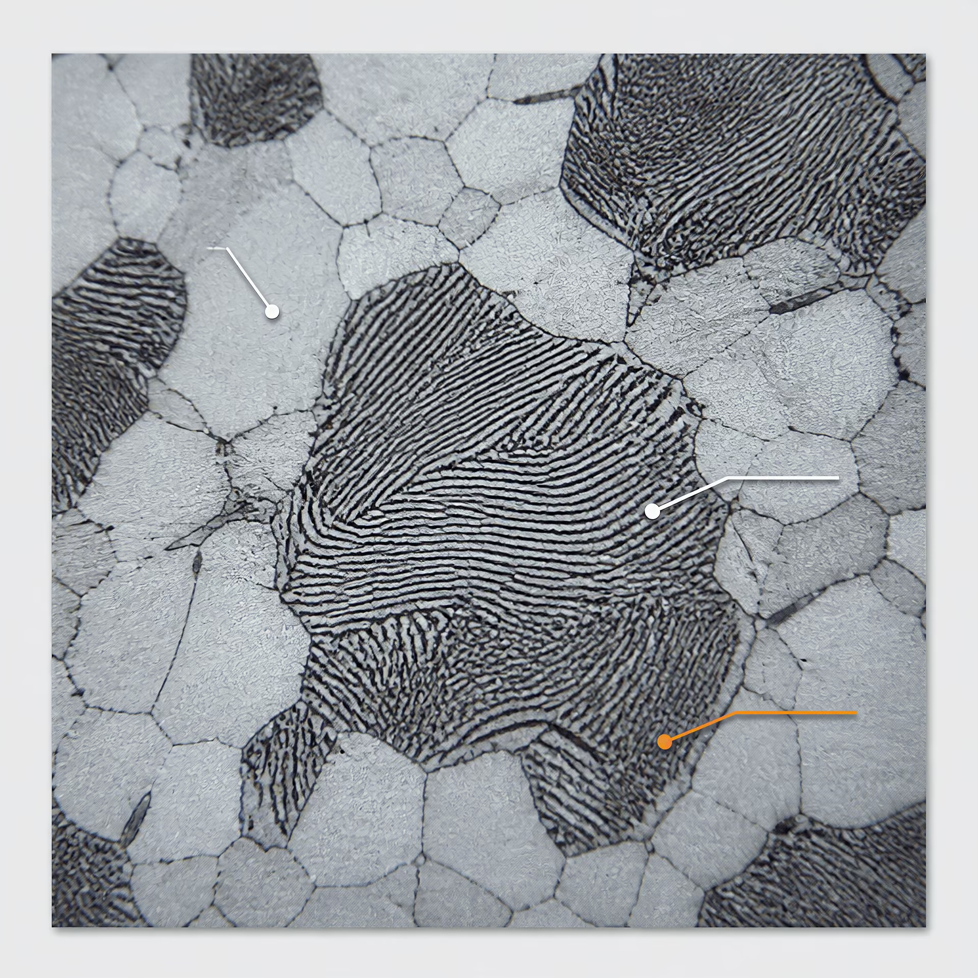
Pearlite forms when austenite decomposes cooperatively into alternating ferrite and cementite. In a conventional coarse-pearlite colony, the two phases appear as lamellae; at lower transformation temperatures, the interlamellar spacing becomes finer. Pearlite is therefore a two-phase microconstituent, not a single crystallographic phase. Its hardness rises as the lamellar spacing decreases because fine cementite barriers restrict dislocation motion. Coarse pearlite generally offers greater ductility and machinability than fine pearlite, while fine pearlite can provide a useful combination of strength, wear resistance, and moderate toughness.
Pearlite formation is diffusion-controlled. Carbon must redistribute from regions becoming ferrite into cementite, so the transformation requires time at a suitable temperature. A slow furnace cool promotes relatively coarse pearlite, while normalizing produces finer pearlite through faster air cooling and a finer prior-austenite grain structure. Neither response is universal: alloy content, carbon level, section thickness, and cooling conditions determine the actual colony size and fraction. Pearlite may also contribute to dimensional change because transformation from austenite involves a change in specific volume, and nonuniform cooling can leave residual stress.
Bainite forms from austenite at temperatures below the pearlite range and above the temperature at which martensite begins to form, although the boundaries are not fixed constants for every steel. It consists mainly of ferritic regions containing carbon-enriched areas and carbide particles. Upper bainite typically forms at higher transformation temperatures, with carbides between ferritic laths or plates; lower bainite forms at lower temperatures, with finer carbides within or closely associated with the ferrite. Exact morphology depends on carbon content, alloying, transformation temperature, and cooling path.
Bainite is also a microconstituent rather than a single phase. Its hardness commonly exceeds that of coarse pearlite and may approach or overlap the lower range of tempered martensite, but no single hardness should be assigned without specifying composition and condition. Bainitic structures can provide useful strength and wear resistance while retaining more toughness than untempered martensite. Austempering is designed to form a controlled bainitic structure, yet incomplete transformation can leave retained austenite. Distortion may be lower than with a direct quench in some geometries because the transformation occurs more uniformly, but thermal gradients and transformation stresses remain significant.
Martensite and retained austenite
Martensite forms when austenite cools rapidly enough to suppress the diffusion-controlled formation of pearlite and bainite. It is a diffusionless, displacive transformation product: carbon does not have time to partition into equilibrium cementite during the transformation, so it remains trapped in a supersaturated iron lattice. In carbon steel, the resulting structure is commonly described as body-centered tetragonal (BCT), although tetragonality depends strongly on carbon content and may be small in low-carbon martensite. Martensite can appear as laths in low- and medium-carbon steels or as plates in higher-carbon steels.
Fresh, untempered martensite is hard because its supersaturation, lattice strain, high dislocation density, and transformation substructure obstruct plastic deformation. That hardness can improve resistance to indentation and abrasive wear, but untempered martensite often has limited toughness and may be vulnerable to cracking, especially when carbon content, prior-austenite grain size, quench severity, and residual stress are high. Tempering permits controlled carbide precipitation and stress relief, reducing hardness in exchange for improved ductility and fracture resistance. The selected tempering condition must match the service requirement rather than treating maximum hardness as the sole objective.
Not all austenite necessarily transforms during quenching. Austenite remaining below the martensite-finish temperature is called retained austenite. Its amount depends on carbon and alloy content, austenitizing conditions, cooling rate, and the temperatures Ms and Mf. Retained austenite can improve toughness in some carefully controlled structures, but it is also dimensionally unstable. It may transform to martensite during service, subzero treatment, grinding, impact, or tempering, causing delayed expansion, hardness change, or distortion. Its transformation can also generate local stress and initiate cracking when surrounding martensite constrains the volume change.
For this reason, hardness readings alone do not establish whether a quenched steel has the intended microstructure. A specification may require control of retained austenite, grain size, decarburization, or distortion in addition to hardness. ISO 683-1:2016 addresses non-alloy steels intended mainly for quenching and tempering, austempering, flame hardening, induction hardening, and certain normalized conditions. ISO 17663:2023 places heat treatment associated with welding and formed components within a quality-requirements framework, mainly for ferritic steels. Both standards reflect the practical point: phase selection and transformation control must be tied to composition, geometry, thermal history, and the required mechanical and dimensional response.
Austenitizing: The Starting Point for Many Treatments
Austenitizing sequence
- Heat Raise the component into the required austenite-forming range.
- Equalize Allow the coldest significant region to reach the required condition.
- Dissolve selectively Redistribute carbon and, where intended, dissolve part of the carbide population.
- Control grain size Avoid unnecessary temperature or holding time that promotes austenite grain growth.
- Transfer promptly Begin the specified cooling path without an uncontrolled delay.
Austenitizing is the controlled heating of steel into the temperature range where austenite forms, followed by sufficient time at temperature for the required transformation and chemical redistribution. It is the starting stage for many quench-and-temper, martempering, austempering, flame-hardening, and induction-hardening cycles. Without austenite, the subsequent cooling step cannot produce the intended martensite or bainite structure.
The purpose is not simply to make the steel hot. The purpose is to create austenite with the right carbon content, alloying-element distribution, grain size, and spatial uniformity before cooling changes the transformation path. ASTM International’s 2024 steel-metallurgy course outline places austenite alongside ferrite, cementite, pearlite, martensite, and bainite as a central part of the phase-and-process framework. ASM International likewise treats austenitizing as one element within a larger system that includes transformation diagrams, hardenability, quenching, distortion, and residual-stress control.
Heating into the austenite field
In plain-carbon steel, austenitizing begins above the lower critical temperature, where ferrite and pearlite transform toward austenite. The exact temperature depends on carbon content, prior microstructure, heating rate, and alloy additions. A hypoeutectoid steel, such as a typical medium-carbon grade, must usually be heated above the upper critical temperature so that ferrite dissolves and the structure becomes predominantly austenitic. A hypereutectoid steel is often heated between the lower critical temperature and the cementite solvus when some undissolved cementite is intentionally retained.
The iron–iron-carbide diagram describes equilibrium phase stability, but a furnace cycle is not an equilibrium experiment. Heating rate shifts the observed transformation temperatures, and alloying elements may delay austenite formation or carbide dissolution. Chromium, molybdenum, vanadium, tungsten, and titanium can form stable carbides that require higher temperatures or longer holds to dissolve. Nickel and manganese alter transformation temperatures and hardenability without behaving like carbide-forming elements in the same way. Carbon is especially important: it must enter austenite in a controlled amount because its concentration affects martensite start temperature, hardness, retained austenite, and dimensional change.
Austenitizing therefore precedes quenching because quenching transforms the austenite present at the instant cooling begins. If ferrite, pearlite, or undissolved carbides remain beyond the specified amount, the final structure may contain soft regions or a carbon distribution that differs from the design assumption. If the steel is heated too far, however, the remedy is not automatically greater hardness. Excessive temperature can enlarge austenite grains, increase oxidation and decarburization, promote distortion, and dissolve carbides that were intended to restrict grain growth or provide wear resistance.
The same principle applies to surface treatments. In induction or flame hardening, only a near-surface layer may reach the austenite field. The heated depth, peak temperature, and time above the critical range determine the hardened case. A short, intense cycle can preserve a fine grain size, but it also creates steep thermal gradients and demands accurate control of power, travel speed, coupling, and cooling.
Dissolution, grain growth, and homogenization
When ferrite and pearlite transform, cementite dissolves and carbon diffuses into the new austenite. The process is not instantaneous. A part may show the correct furnace temperature while its center is still below the transformation range, especially when the section is thick, the load is dense, or the furnace circulation is poor. Holding time should therefore be based on the time required for the coldest significant region of the component to reach temperature, not merely on the moment when the furnace display reaches its setpoint.
Dissolution has competing effects. Enough time and temperature are needed to remove unwanted pearlite or ferrite and to distribute carbon so that austenite can transform as intended during cooling. In alloy steels, some carbides may need partial dissolution to supply carbon and alloying elements to austenite. Complete dissolution may be undesirable. Retained alloy carbides can limit austenite grain growth, contribute to wear resistance, and control the carbon level of the matrix.
Grain growth accelerates when austenite is held at unnecessarily high temperature. Coarse prior-austenite grains reduce toughness and can increase the severity of quench cracking or fracture sensitivity, even when hardness meets a nominal target. They also alter transformation kinetics and can change the depth and uniformity of hardening. Fine-grained austenite is not produced by a single universal holding time; it results from matching temperature, heating rate, starting condition, alloy chemistry, and section size.
Prior processing matters. Normalized, annealed, forged, cold-worked, and welded steel may enter the furnace with different carbide distributions, grain sizes, and residual stresses. A forged 42CrMo4 component and a thin sheet of the same nominal grade will not respond identically to the same schedule. ISO 683-1:2016 addresses non-alloy steels intended mainly for quenching and tempering, austempering, flame hardening, induction hardening, and, in some cases, normalized conditions; the grade designation and specified delivery condition remain essential inputs to the cycle.
Austenitizing can also homogenize local chemistry, but only within practical limits. Segregation from casting, banding from rolling, weld-metal variation, and surface contamination may persist if diffusion distances are large. Longer holding may reduce some gradients while causing grain growth and surface damage. Heat treatment cannot erase every prior-processing defect.
Time, temperature, and atmosphere control
A furnace setpoint is only one control variable. The actual thermal cycle includes heating rate, load arrangement, part temperature, temperature uniformity, hold duration, transfer time to the quench, and the atmosphere surrounding the steel. Geometry governs all of them. Thin edges heat rapidly and may overheat before a thick hub reaches the target temperature; holes, keyways, threads, and abrupt section changes create local thermal and stress concentrations. Fixturing can shadow surfaces from radiant heat or restrict circulation.
Thermocouples placed near the furnace wall may report a stable temperature while the component center remains colder. Production practice therefore uses qualified furnace surveys, load thermocouples, representative test pieces, or validated heat-transfer models where necessary. ISO 17663:2023 sets quality requirements for heat treatment in air or controlled atmospheres performed in workshops or on site, mainly for ferritic steels and related welded or formed components. Its scope reflects the practical issue: repeatable results require documented equipment, monitoring, calibration, and acceptance criteria.
Atmosphere control protects the surface chemistry. Oxidizing furnace gases produce scale, while decarburizing conditions remove carbon from the surface. A decarburized layer may lower surface hardness after quenching even when the core composition and hardness are correct. Vacuum, inert gas, salt, or controlled endothermic atmospheres can reduce these effects, but each introduces its own process controls and safety requirements. Surface condition must be checked by hardness traverses, metallography, dimensional inspection, or chemical-depth measurement when the application demands it.
Time at temperature should be long enough for the required transformation and temperature equalization, but no longer. Cooling must begin promptly when the specified austenite condition is reached, since transfer delays can alter the thermal history, especially in high-hardenability steels or large components. The final result comes from the entire time–temperature path, not from a number written on a furnace controller. That distinction is where repeatable austenitizing begins.
Transformation Diagrams and Heat-Treatment Kinetics
A heat-treatment schedule cannot be selected from temperature alone. The steel must first be austenitized, then taken through a particular time–temperature path that determines whether austenite becomes ferrite, pearlite, bainite, or martensite. Carbon content, alloy additions, prior grain size, section thickness, heating rate, and the condition of the starting structure all affect that path. Transformation diagrams provide a way to connect these variables with observable events: the beginning of transformation, the rate at which it proceeds, and the point at which it is substantially complete.
The iron–iron-carbide phase diagram describes equilibrium or near-equilibrium phase stability. It does not predict the result of a rapid quench. TTT and CCT diagrams address that missing question by showing how transformation depends on time as well as temperature. ASM International’s 2024 treatment of steel fundamentals places these diagrams alongside austenitizing, hardenability, quenching, annealing, tempering, and residual-stress control because none of those operations can be specified reliably without considering transformation kinetics.

Time–temperature–transformation diagrams
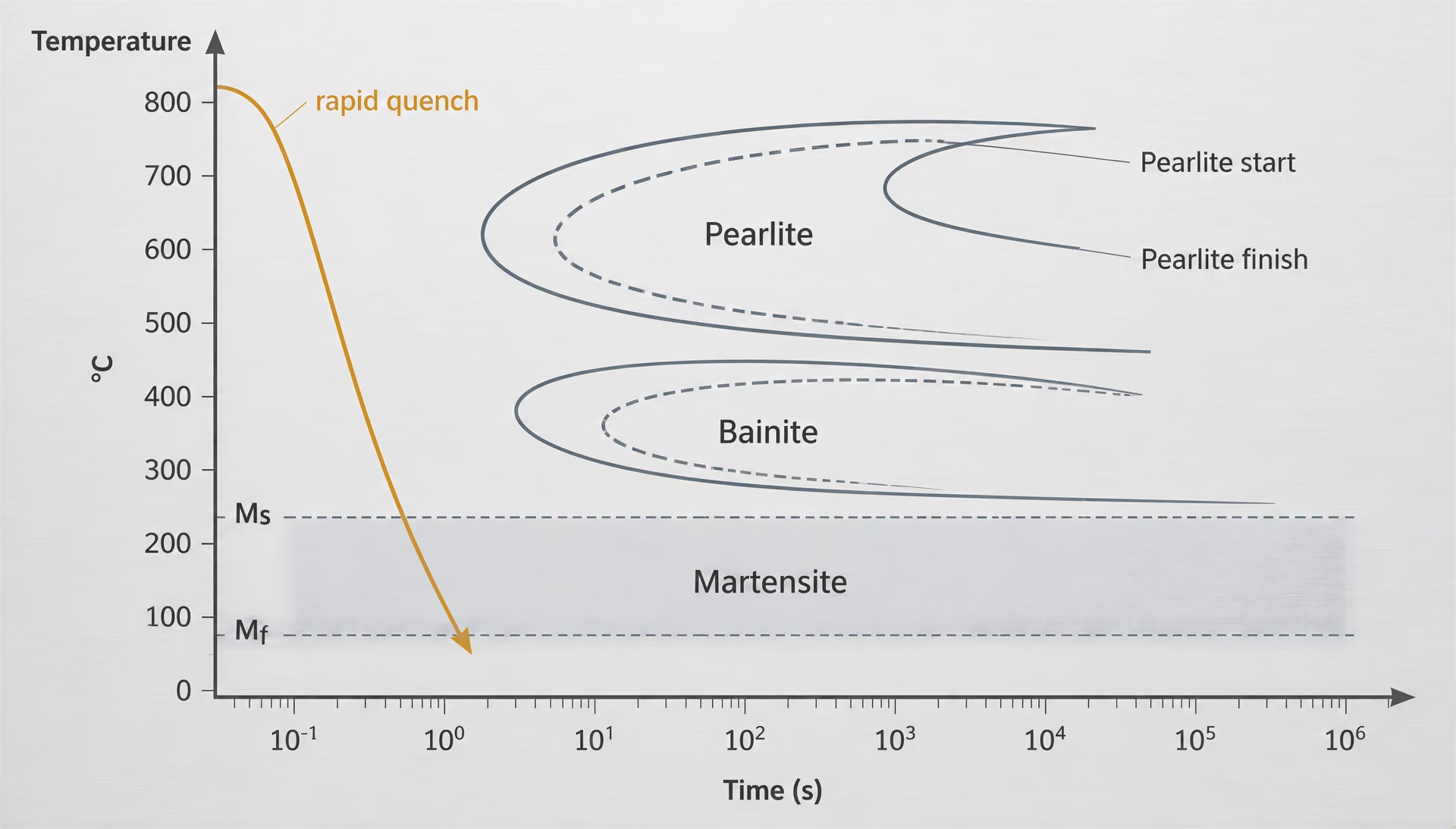
A time–temperature–transformation diagram, commonly called a TTT diagram or isothermal transformation diagram, is generated by heating specimens into the austenite region, rapidly transferring them to selected constant temperatures, holding them there, and measuring when transformation begins and ends. Time is plotted on a logarithmic horizontal axis, while temperature is plotted vertically. The resulting start and finish curves often form a characteristic C shape for pearlitic and bainitic reactions.
The start curve marks the approximate incubation period before a detectable fraction of austenite has transformed. The finish curve indicates when the selected transformation is substantially complete according to the test method. Between the curves, ferrite, pearlite, or bainite develops progressively; the diagram is not saying that the entire specimen changes phase at one instant. A horizontal line at a chosen temperature therefore intersects the start curve after an incubation time and reaches the finish curve after a longer holding period.
At temperatures just below the eutectoid range, austenite may form coarse pearlite, with relatively widely spaced ferrite and cementite. At lower temperatures, the interlamellar spacing decreases and pearlite becomes finer. A still lower temperature range can produce bainite, whose ferrite and carbide arrangement differs from pearlite. The exact boundaries depend on steel composition and test conditions. Alloying elements such as chromium, molybdenum, nickel, and manganese generally retard diffusion-controlled reactions by changing phase stability and substitutional diffusion rates, though their effects are not identical in every grade.
| Diagram or route | Key condition | Typical transformation or purpose |
|---|---|---|
| TTT | Constant-temperature holding | Pearlite or bainite transformation kinetics |
| CCT | Continuous cooling | Practical furnace and quench paths |
| Austempering | Hold above Ms and below the pearlite range | Isothermal bainite formation |
| Martempering | Hold near Ms for temperature equalization | Reduced thermal gradient before martensite forms |
A TTT diagram is especially useful for understanding isothermal treatments such as austempering. Austenite is cooled rapidly to a selected bainitic temperature, held until the desired transformation occurs, and then cooled to room temperature. The diagram helps determine whether the cooling path avoids pearlite and whether the hold is long enough to transform the required amount of austenite. It can also show why a hold that seems adequate for one composition fails for another.
The martensite-start temperature, designated , is treated differently. Martensite is a diffusionless transformation: carbon does not have time to partition into cementite while the lattice changes from austenite to a supersaturated body-centered tetragonal structure. Martensite begins when the steel is cooled below its composition-dependent , and the amount formed generally increases as temperature falls toward the martensite-finish temperature, . The reaction is not controlled by an incubation period in the same manner as pearlite formation. If the quench stops above , martensite does not begin; if it stops between and , some austenite may remain untransformed.
Continuous-heating and continuous-cooling diagrams
Industrial furnaces and quenching systems rarely reproduce the abrupt temperature changes used to construct a TTT diagram. A component heats continuously, may develop temperature gradients through its section, and then cools continuously in air, oil, polymer, water, salt, or a controlled gas. Continuous-heating-transformation (CHT) diagrams describe transformation during heating at a specified rate, while continuous-cooling-transformation (CCT) diagrams describe transformation during uninterrupted cooling.
A CCT diagram usually contains several cooling curves, each representing a different cooling rate. A slow curve may cross the ferrite and pearlite start regions, producing diffusional products before it reaches the bainite or martensite range. A faster curve can bypass those regions and enter the martensite field. The cooling rate required to avoid transformation before is the critical cooling rate for the particular specimen and austenitizing condition, not a universal value for a steel family.
The curve’s intersection with transformation-start and transformation-finish boundaries gives a practical prediction of the products formed. For example, a cooling path for an AISI 1045 specimen may pass through ferrite–pearlite regions that a comparable path through an AISI 4140 specimen avoids, because chromium, molybdenum, and manganese shift the transformation reactions to longer times. The two grades therefore cannot share one generic CCT diagram, even if both are quenched and tempered.
CCT diagrams are generally more useful than TTT diagrams for normalizing, air cooling, direct quenching, and production furnace cycles. They can indicate whether the surface and center of a thick part will follow different paths. The center cools more slowly because heat must travel through the surrounding material, so it may form pearlite or bainite while the surface reaches martensite. This is the basis of hardenability: not simply the maximum hardness obtainable at the surface, but the depth to which a specified structure or hardness can be produced under a defined quench.
Neither diagram is a universal map. A diagram identified for AISI 4140, for example, may have been produced using a stated carbon range, austenitizing temperature, holding time, prior grain size, specimen geometry, and cooling medium. Altering any of these can move transformation behavior. A finer prior-austenite grain size supplies more nucleation sites and can accelerate some diffusional transformations; excessive grain growth can delay them. A commercial heat-treatment cycle must therefore be checked against the actual heat, dimensions, furnace uniformity, and quench conditions.
Nucleation, growth, and transformation-rate effects
Diffusion-controlled transformation requires both nucleation and growth. Nucleation creates small regions of a new phase, while growth carries atoms across the interface and enlarges those regions. At temperatures close to the equilibrium transformation temperature, the driving force may be too small for rapid nucleation. At much lower temperatures, diffusion becomes slow. Transformation is often fastest at an intermediate temperature, which explains the nose of the C-shaped start curve.
Incubation is the period before enough stable nuclei form for transformation to be detected. It is not wasted time in a general process sense; it reflects the competition between thermodynamic driving force, interfacial energy, and atomic mobility. Holding austenite near the nose of a TTT diagram can therefore consume very little time before pearlite begins, whereas a hold at a higher temperature may require much longer incubation.
Growth rate also controls the resulting structure. Faster growth at higher transformation temperatures tends to produce coarser pearlite, while lower-temperature transformation yields finer spacing and usually higher strength. Bainite forms through a different combination of ferrite growth and carbon redistribution, and its morphology changes with temperature. Martensite bypasses ordinary diffusion-controlled growth, but it generates high dislocation density, lattice strain, and residual stress; tempering is commonly required to reduce those effects and adjust hardness and toughness.
Laboratory diagrams isolate variables in small specimens. Production components do not. A forged shaft may enter the furnace with segregation, scale, residual stress, and a nonuniform prior structure. Its surface may heat and cool faster than its core, while corners, holes, and sharp transitions alter heat flow. ISO 17663:2023 therefore treats heat treatment associated with welding and allied processes as a quality-controlled operation performed in workshops or on site, including attention to thermal records and process conditions. ISO 683-1:2016, meanwhile, sets delivery requirements for non-alloy steels intended primarily for quenching and tempering, austempering, flame hardening, induction hardening, and selected normalized conditions.
Transformation diagrams guide the route, but they do not replace measurement. Thermocouples, hardness surveys, metallographic examination, and records of furnace and quench conditions are needed to confirm that the intended path was actually followed. The meaningful question is not whether a steel was “heated and cooled,” but which transformations occurred, where they occurred, and how their timing created the final balance of hardness, toughness, distortion, and residual stress.
Annealing and Normalizing Treatments
| Treatment | Heating condition | Cooling condition | Typical result |
|---|---|---|---|
| Full annealing | Into the austenite region | Slow furnace cooling | Soft, comparatively coarse ferrite–pearlite structure |
| Spheroidizing | At or just below Ac1, often repeatedly | Slow controlled cooling | Rounded cementite particles in ferrite |
| Process annealing | Below Ac1 | Controlled cooling | Recrystallized, softer low-carbon steel |
| Normalizing | Into the austenite region | Still-air cooling | Finer and often stronger ferrite–pearlite structure |
Annealing is not one fixed heating-and-cooling recipe. It is a family of thermal cycles selected to change hardness, ductility, machinability, residual stress, grain structure, or the condition left by an earlier process. The required cycle depends on carbon content, alloy additions, section size, prior deformation, heating rate, holding time, furnace temperature uniformity, and the intended cooling path. A treatment that softens a thin low-carbon sheet may be unsuitable for a thick medium-carbon forging, even when both are described as “annealed.”
The phase changes behind these treatments are usually discussed with the iron–iron-carbide diagram, but that diagram gives equilibrium relationships rather than the time required for transformation. Heating and cooling rates shift the actual response. Continuous-heating and continuous-cooling transformation diagrams, along with time–temperature–transformation diagrams, show when austenite forms and when it decomposes into ferrite, pearlite, bainite, or other products. ASM International’s 2024 treatment of steel heat treatment specifically places annealing, austenitizing, transformation diagrams, hardness, and residual-stress control within the same process framework.
Full annealing and related softening cycles
Full annealing generally consists of heating steel into the austenite region, holding long enough for the section to reach a suitable condition, and cooling slowly in the furnace. For a hypoeutectoid steel, the austenitizing temperature is normally above the upper critical temperature, Ac3, so the original ferrite and pearlite dissolve sufficiently to form austenite. For a hypereutectoid steel, the cycle is usually selected above Ac1 but below Acm, leaving some proeutectoid cementite rather than dissolving every carbide. Exact practice varies with grade and section size.
During slow furnace cooling, austenite transforms comparatively close to equilibrium. Hypoeutectoid compositions produce proeutectoid ferrite followed by pearlite; eutectoid steel transforms mainly to pearlite; hypereutectoid steel forms pearlite with proeutectoid cementite. The resulting structure is usually softer and coarser than the structure produced by air cooling. Coarser pearlite has greater interlamellar spacing, which reduces resistance to cutting and deformation but also lowers strength and hardness.
The objective is often softening before machining or cold forming. Full annealing can reduce cutting forces, lessen tool wear, and make hardness more uniform through a large forging or casting. It can also replace a nonuniform cast structure or an overheated prior structure with a more predictable ferrite–pearlite arrangement. It does not automatically remove every defect: segregation, excessive grain growth, decarburization, and carbide networks may remain or become more apparent if temperature and holding time are poorly controlled.
A thick section complicates the result. Its surface follows the furnace temperature more quickly than its core, while the core cools more slowly and may transform at a different temperature. The outside can therefore contain finer pearlite than the center, or can experience different ferrite formation, even when the furnace cycle is recorded correctly. Temperature measurement must represent the workpiece, not merely the furnace atmosphere.
Spheroidizing is another softening cycle, particularly important for high-carbon steels and tool steels that must be machined before hardening. Extended holding just below Ac1, or repeated heating through Ac1 followed by slow cooling, encourages cementite to form rounded particles in a ferritic matrix. Spheroidized carbides generally make high-carbon steel easier to machine than a fine lamellar pearlite structure and provide a useful starting condition for subsequent austenitizing. The cycle can be lengthy because cementite must change shape by diffusion; a short furnace soak cannot produce the same result.
Isothermal annealing offers closer control than ordinary furnace cooling. The steel is cooled from the austenitizing range to a selected temperature in the pearlite transformation range, held until transformation is substantially complete, and then cooled to room temperature. The hold can produce a more uniform structure and shorten the total cycle for some grades, but it requires controlled equipment and a composition-specific transformation schedule.
Process annealing and stress relief
Process annealing is usually a subcritical treatment applied to low-carbon or low-alloy steel after cold working. The material is heated below Ac1, often in a range selected to permit recrystallization without forming austenite, then held and cooled at a controlled rate. New, relatively strain-free ferrite grains replace the elongated and distorted grains produced by rolling, drawing, bending, or pressing. Hardness falls, ductility returns, and the steel becomes more capable of undergoing another forming operation.
The temperature must be high enough for recrystallization but not so high that unwanted grain growth occurs. Prior reduction matters: heavily cold-worked steel has more stored energy and may recrystallize more readily than lightly deformed material. Carbon content and alloying elements also affect recrystallization kinetics. A cycle suitable for a low-carbon sheet cannot be transferred directly to a higher-carbon or alloyed grade.
Stress-relief annealing addresses a different problem. Residual stresses arise from welding, machining, uneven cooling, casting, forming, or local heating. A subcritical hold allows limited diffusion and plastic accommodation to reduce stress without deliberately transforming the matrix. The treatment can reduce distortion during later machining and lower the risk of cracking or dimensional movement, but it does not make residual stress vanish uniformly. Sharp geometry, weld restraint, temperature gradients, and unequal section thickness still matter.
Stress relief after welding requires attention to the weld metal, heat-affected zone, base metal, and component restraints. ISO 17663:2023 gives quality requirements for heat treatment in air or controlled atmospheres, in workshops or on site, mainly for ferritic steels and related welded or formed components. Its relevance is practical: furnace calibration, thermocouple placement, heating and cooling rates, support conditions, and records can affect the result as much as the nominal temperature.
Normalizing and grain refinement
Normalizing usually means heating steel into the austenite region, holding for transformation readiness, and cooling in still air rather than inside a furnace. Air cooling is faster than furnace cooling, so austenite transforms at a lower temperature and produces finer ferrite and pearlite in many carbon and low-alloy steels. The normalized condition is commonly stronger and harder than the fully annealed condition, while retaining useful ductility.
The word “refinement” needs qualification. Normalizing can refine coarse grains produced by forging, casting, welding thermal cycles, or excessive heating, but it cannot correct every form of segregation or eliminate a continuous carbide network. Grain refinement depends on the austenite grain size established during heating. Excessive temperature or holding time can grow austenite grains before air cooling, undermining the intended result.
Carbon content changes both transformation temperature and final proportions. Increasing carbon generally increases the pearlite fraction up to the eutectoid composition and raises hardness after normalizing. A low-carbon grade may remain predominantly ferritic with relatively little pearlite; a medium-carbon grade develops more pearlite and higher strength; a hypereutectoid grade may form pearlite plus proeutectoid cementite. Alloying elements can delay transformation and alter the ferrite–pearlite balance, so some steels may form bainite or other products under air cooling if the section is thin or the cooling rate is sufficiently high.
Section size reverses that situation. A thin part loses heat rapidly and may normalize to a finer structure, while the core of a heavy section cools slowly and may approach an annealed condition. Geometry, contact with fixtures, furnace loading, and air movement add further variation. Normalizing is therefore a defined cooling practice, not simply a label for any steel cooled outside a furnace. ISO 683-1:2016 recognizes non-alloy steels supplied for several heat-treatment conditions, including, in some cases, normalized conditions; the specified grade and delivery condition still govern the acceptable microstructure and properties.
Quenching, Hardening, and Hardenability
[5] Basic Principles and Design Guidelines for Heat Treatment. ASM International. ASM Handbook chapter, 2024.
Quenching is not simply rapid cooling after heating. It is a planned attempt to move an austenitized steel through temperature ranges fast enough to suppress diffusional transformations, such as pearlite and proeutectoid ferrite, while producing martensite or another specified hardened structure. The result depends on composition, austenite grain size, section geometry, temperature uniformity, the cooling curve, and the stresses generated during transformation. ASM Handbook Volume 4A treats these variables together with austenitizing, hardness, hardenability, quenching, tempering, austempering, martempering, and surface hardening (ASM International, 2024).
Quenching and martensitic transformation
Before quenching, steel is heated into austenite-forming conditions. For hypoeutectoid steels, this normally means heating above the upper critical temperature so ferrite and pearlite dissolve sufficiently into austenite. In a eutectoid steel, the pearlitic mixture must transform to austenite; in hypereutectoid steel, the treatment may retain some proeutectoid cementite depending on the specified temperature. Holding time must allow the section to reach a suitable and reasonably uniform condition, but excessive time or temperature can enlarge austenite grains, increase oxidation, and worsen distortion.
Austenite can dissolve substantially more carbon than ferrite. During slow or moderate cooling, carbon has time to diffuse, allowing ferrite, cementite, or pearlite to form. Rapid cooling removes that time. If the cooling path avoids the pearlite and bainite transformation regions on a time-temperature-transformation diagram, the austenite reaches the martensite-start temperature, Ms. Martensite then forms by a diffusionless shear transformation as carbon remains trapped in a supersaturated body-centered tetragonal structure. Further cooling produces additional martensite until the martensite-finish temperature, Mf, is approached.
Martensite raises hardness because its distorted lattice resists dislocation movement. Carbon content strongly affects that response: higher dissolved carbon generally increases the hardness of as-quenched martensite and lowers Ms and Mf. A steel may therefore retain some untransformed austenite after room-temperature cooling, particularly when carbon and alloy content are high or the section does not reach a sufficiently low temperature. Retained austenite can later transform during service, machining, subzero treatment, or tempering, changing dimensions and stresses.
The centre of a large part cools more slowly than its surface. That difference can allow pearlite or bainite to form in the interior even when the surface becomes martensitic. Quenching also creates thermal gradients: the surface contracts first, while the hot core resists that contraction. Transformation strain adds another source of stress because austenite-to-martensite transformation involves a volume increase. Cracking is the extreme result, but distortion, residual stress, and dimensional change are more common. The desired structure must therefore be judged across the section, not from a surface hardness reading alone.
Tempering normally follows quenching. It reduces quench stresses and changes supersaturated martensite into tempered martensite through controlled precipitation and recovery reactions. The selected tempering temperature and time determine the balance among hardness, strength, toughness, and dimensional stability. A quenched part that is left untempered may have high hardness but poor resistance to cracking or impact.
Hardness versus hardenability
Hardness is a measured resistance to localized deformation. Rockwell C, Vickers, and Brinell tests report what happens at a particular test location under a defined load, indenter, and procedure. A surface hardness value does not state how deeply the part hardened, whether the core is martensitic, or whether the result came from quenching, carburizing, induction hardening, or another treatment.
Hardenability is different. It is the ability of a steel section to develop a hardened structure through its depth under specified austenitizing and quenching conditions. It describes transformation response, not a single hardness number. Two steels can reach similar maximum surface hardness when fully martensitic, yet differ greatly in the depth at which that hardness is maintained. Carbon largely determines the maximum hardness of martensite; alloying elements such as manganese, chromium, molybdenum, and nickel generally delay diffusional transformations and increase hardenability. Boron can have a strong effect in very small controlled additions when it remains effective at austenite grain boundaries.
Jominy end-quench test A standardized test in which one end of an austenitized specimen is water-quenched and hardness is measured at distances from the quenched end to characterize hardenability.
The Jominy end-quench test expresses hardenability as a hardness profile along a standardized specimen. Water impinges on one end, creating a range of cooling rates along its length. Hardness measured at fixed distances reveals how far the steel can form martensite under that test condition. The curve is not a direct guarantee for every component. A thick gear, a thin plate, and a complex casting have different thermal histories, even when made from the same heat of steel.
Section size is decisive because heat must travel from the interior to the cooling surface. A small diameter may cool rapidly throughout, while a heavy section may develop martensite only near its exterior. Geometry changes the situation further: holes, sharp corners, keyways, thin webs, and abrupt thickness transitions concentrate heat flow and stress. Austenite grain size also affects hardenability. Coarser grains provide fewer nucleation sites for ferrite and pearlite, often delaying those transformations, but excessive grain growth reduces toughness and can increase distortion or cracking.
Hardenability should not be confused with “hardness after any quench.” A high-carbon steel can be very hard at the surface yet show limited depth of hardening. Conversely, a medium-carbon alloy steel may have lower maximum martensitic hardness but develop that structure farther into a large section. The treatment specification must state the steel grade, austenitizing temperature, holding conditions, quenchant, agitation, part geometry, and acceptance locations.
Cooling media and severity
Variables that change quench severity
- Medium Water, brine, oil, polymer, gas, or an interrupted route provides a different cooling response.
- Agitation Fluid movement breaks up vapour films and renews cooler fluid at the surface.
- Condition Temperature, concentration, contamination, degradation, and bath volume alter cooling.
- Geometry Corners, holes, webs, and thick sections create local cooling differences.
- Orientation Part placement changes fluid access and the resulting cooling curve.
Water, brine, oil, polymer solutions, gas, and interrupted cooling are classes of cooling practice, not interchangeable recipes. Their performance depends on temperature, concentration, agitation, contamination, bath volume, part loading, and surface condition. Even the same nominal quenchant can produce different cooling curves in different equipment.
Water usually provides strong cooling in the high-temperature range, but vapour-film formation can temporarily insulate a hot surface. As the vapour blanket collapses, cooling may become severe and uneven. Brine reduces vapour-film persistence and can cool more aggressively, increasing the risk of distortion and cracking. These media may be unsuitable for intricate shapes or steels with high hardenability when a less severe quench can achieve the required structure.
Oil generally cools less violently than water or brine and can reduce thermal shock, although oil type, temperature, agitation, oxidation, and contamination change its behaviour. Polymer solutions occupy a broad range: concentration and circulation can be adjusted to alter cooling severity, but control is required because concentration drift changes the process. Gas quenching, including pressurized inert gas, can provide cleaner and more uniform cooling, yet its severity may be insufficient for a large section or a low-hardenability grade.
Cooling severity concerns the relationship between the quenchant and the part surface, not merely the name of the medium. Agitation breaks up vapour films and renews cooler fluid at the surface. Excessive or uneven agitation can produce nonuniform hardness and distortion. A quenchant in poor condition may contain water, degraded polymer, sludge, or excessive oxidation products; its cooling curve then departs from the qualified process.
Interrupted cooling changes the path deliberately. In martempering, the part is cooled rapidly to a temperature above or near Ms, held long enough for temperature equalization without permitting significant bainite or pearlite formation, and then cooled through the martensite range. This reduces the difference between surface and core temperatures and can lower distortion, but it does not remove transformation stress. Austempering instead transfers the austenitized steel to a bath where bainite forms isothermally, producing a specified hardened structure without requiring ordinary martensitic quenching.
ASM’s 2024 treatment of transformation diagrams and residual-stress control makes the central point clear: the quench must be designed from the steel’s continuous-cooling behaviour and the part’s thermal history. ISO 683-1:2016 covers non-alloy steels intended primarily for quenching and tempering, austempering, flame hardening, induction hardening, and some normalized conditions. For welded or formed ferritic-steel components, ISO 17663:2023 places heat treatment within a quality-controlled process that may occur in a workshop or on site. Neither standard makes one cooling medium universally suitable. The correct choice is the one that produces the required structure and properties while keeping hardness variation, distortion, residual stress, and cracking within specified limits.
Tempering and the Control of Quenched Steel
Why as-quenched martensite is rarely the final condition
Quenching can produce martensite, but martensite is a condition created by suppressing diffusion, not a stable endpoint for most engineering components. During quenching, austenite transforms into a supersaturated, distorted body-centred tetragonal structure in which carbon has little time to redistribute. The result can be very high hardness and strength, yet also substantial residual stress, low ductility, poor fracture resistance, and dimensional instability.
The problem is not simply that the steel is “too hard.” Different regions of a component cool at different rates. The surface may transform before the core, while corners and holes impose local restraints. Thermal contraction, transformation strain, retained austenite, and the volume change associated with martensite formation can combine to produce tensile stresses, distortion, or quench cracking. A large section may also contain a mixture of martensite, bainite, pearlite, and retained austenite rather than a single uniform structure. Carbon content, alloying additions, hardenability, section size, quenching medium, agitation, and geometry all affect that outcome.[6] Steel and Its Heat Treatment. Elsevier. Technical reference, 1984.
Tempering is the controlled reheating of quenched steel to a temperature below the relevant transformation range, commonly below the temperature at which new austenite would form. The steel is held long enough for selected diffusion and precipitation reactions to occur, then cooled under controlled conditions. This treatment reduces brittleness and residual stress while adjusting hardness, tensile strength, toughness, wear resistance, and dimensional stability.
As ASM International explains in its 2024 heat-treatment material, steel tempering must be considered alongside austenitizing, transformation diagrams, hardness and hardenability, quenching, distortion, and residual-stress control. That relationship matters. Tempering cannot repair an unsuitable austenitizing practice or an uncontrolled quench; it modifies the structure that the earlier stages have created.
Tempering reactions and property balance
Tempering begins with the redistribution of carbon trapped in martensite. At the earliest stage, carbon moves over short distances and may form transition carbides while the tetragonal distortion of martensite decreases. The matrix becomes less supersaturated, and some of the stress associated with the as-quenched lattice is relieved. This can produce a modest reduction in hardness while improving resistance to cracking.
With further tempering, transition structures give way to more stable carbide arrangements. In plain-carbon steels, cementite becomes the principal carbide, developing within a ferritic matrix as the martensitic structure loses its extreme supersaturation. In alloy steels, chromium, molybdenum, vanadium, tungsten, or other carbide-forming elements can alter precipitation reactions and may produce alloy carbides at suitable thermal histories. These reactions are not instantaneous. Temperature determines which reactions are possible and how rapidly they proceed; time determines how far they advance.
The property balance therefore depends on the full time-temperature history, not on a nominal furnace setting alone. Higher tempering temperatures generally accelerate carbon redistribution and carbide coarsening, causing a larger reduction in hardness and strength but often a useful increase in toughness and ductility. Lower temperatures preserve more hardness while relieving less stress and leaving more of the quenched structure chemically and mechanically unstable. The actual response depends on carbon level, alloy content, prior austenite grain size, martensite morphology, retained austenite, and the size of the component.
Retained austenite deserves particular attention. It may transform during tempering or later service, producing a dimensional change that is unacceptable in precision parts. A tempering schedule can be designed to reduce this risk, but the result depends on the steel grade and the amount and stability of retained austenite. Some components require more than one tempering cycle, with cooling between cycles, so that newly transformed constituents receive a subsequent temper. Repeat cycles may also improve dimensional stability where the first cycle reveals or induces additional transformation.
Time at temperature must be sufficient for the coldest or least-heated region of the load, not merely for the furnace display to reach its set point. Thick sections, tightly packed loads, and parts with large differences in mass can develop temperature gradients. Heating uniformity is consequently a metallurgical variable. A surface that reaches the intended temperature early may overtemper while the core is still approaching it. Furnace calibration, load arrangement, part spacing, atmosphere control, and monitoring at representative locations are part of the treatment, especially when strength or dimensional tolerances are specified.
The distinction between equilibrium and transformation behavior remains useful here. The iron–iron-carbide diagram indicates equilibrium phase relationships, while tempering depends on kinetic reactions that occur during a finite thermal cycle. ASM’s 2024 discussion of steel heat treatment separates these equilibrium concepts from time-temperature-transformation and continuous-heating or continuous-cooling behavior. Tempering is another kinetic process: two schedules reaching the same nominal temperature can produce different structures if their heating rates, holding times, cooling rates, or prior quench conditions differ.
ISO 683-1:2016 addresses technical delivery requirements for non-alloy steels intended primarily for quenching and tempering, among other conditions. For welded or formed ferritic-steel components, ISO 17663:2023 places heat treatment within a quality-control framework covering work performed in workshops or on site, in air or controlled atmospheres. Neither standard makes one tempering cycle suitable for every grade or geometry. The specified steel, product form, section size, and required properties still govern the procedure.
Temper embrittlement and temperature control
Temper embrittlement is a recognized failure mode rather than an incidental loss of hardness. The technical reference Steel and Its Heat Treatment (Elsevier, 1984) identifies temper brittleness among the central topics in steel heat treatment. In susceptible alloy steels, embrittlement can develop after exposure to certain tempering and cooling histories, particularly when impurity elements segregate to prior-austenite grain boundaries. Phosphorus, tin, antimony, and arsenic are commonly associated with this mechanism, while alloy composition and prior processing affect sensitivity.
The danger is a reduction in impact toughness without a proportionate change in conventional tensile properties. A part may retain an apparently acceptable hardness while becoming more prone to intergranular fracture under impact or at lower service temperatures. The temperature interval and severity are not universal values: they depend on steel chemistry, segregation, austenite grain structure, holding time, and cooling practice. A prescription detached from the grade and specification can therefore be misleading.
Control may involve selecting a less susceptible composition, limiting harmful residual elements, avoiding unsuitable exposure, and applying the specified cooling practice after tempering. In some alloy steels, rapid cooling through the susceptible region after tempering is required; in others, the governing specification may require a different procedure or impact-toughness verification. The correct response is determined by the material standard, component function, and test requirements.
Temperature measurement must represent the steel, not only the furnace atmosphere. Thermocouple placement, furnace uniformity surveys, load size, and transfer time all affect the actual cycle. A delayed transfer or uneven cooling can alter carbide precipitation and embrittlement risk even when the recorded set point appears correct. Tempering is therefore a control problem: composition establishes the possible reactions, quenching establishes the starting structure, and the subsequent time-temperature path determines the balance between hardness, toughness, stress relief, and stability.
Austempering and Martempering
| Process | Hold location | Transformation intended | Main benefit |
|---|---|---|---|
| Austempering | Above Ms and below the pearlite range | Bainite | Controlled bainitic structure and potentially lower distortion |
| Martempering | Near or just above Ms | Martensite during subsequent cooling | Reduced surface-to-core temperature difference before martensite forms |
| Direct quenching | Through the transformation range without an equalizing hold | Usually martensite where cooling is sufficient | Simple route, but greater thermal-gradient risk |
Austempering and martempering are controlled alternatives to a direct quench followed by tempering. Neither is simply a different bath choice. Each imposes a distinct time–temperature path on austenite, and the result depends on whether the steel can avoid pearlite, reach the required transformation range, and remain sufficiently uniform through the section. Carbon content, alloying additions, prior austenite grain size, geometry, and bath capacity all influence that outcome.
The distinction is central. Austempering aims to transform austenite isothermally into bainite before the part is cooled to room temperature. Martempering interrupts the quench near the martensite-start temperature, allowing temperature differences to diminish before martensite forms; the martensitic transformation then occurs during further cooling, followed by tempering. ASM Handbook Volume 4A, published by ASM International in 2024, treats both as separate processes within the wider study of austenitizing, hardenability, quenching, tempering, and residual-stress control.
Isothermal transformation routes
For austempering, the steel is first heated above its critical range to produce austenite. It is then transferred rapidly into a bath held above the martensite-start temperature, , but below the pearlite transformation range. The bath temperature is commonly selected within roughly 250 to 400 °C, although the useful interval varies substantially with grade and the required bainite morphology. The part remains at that temperature until the intended fraction of austenite has transformed to bainite, after which it is cooled to ambient temperature.
This route avoids the direct passage through the pearlite region and, when the transformation is completed, avoids the formation of fresh martensite on final cooling. Bainite consists of ferritic regions formed by a displacive component of transformation together with carbon-enriched retained austenite or carbide, depending on temperature, composition, and terminology applied to the structure. Upper bainite generally forms at higher austempering temperatures; lower bainite forms at lower temperatures and commonly contains finer ferrite and more finely distributed carbide.
A TTT diagram makes the process appear straightforward: bypass the nose, enter the bainite field, hold until transformation finishes, and cool. Actual production is less forgiving. The required transfer time must be shorter than the time available before pearlite begins, while the bath must extract heat rapidly enough to bring the entire section to a nearly uniform temperature. A thick gear tooth, spring, or bearing component may have a surface already transforming while its core is still cooling toward the bath temperature. If the core does not complete the same route, the final structure becomes mixed.
Austempering therefore depends strongly on hardenability and section size. Alloying elements such as manganese, chromium, molybdenum, and nickel generally delay diffusional transformations, moving the pearlite and bainite reactions to longer times, but they also change , bainite kinetics, retained-austenite stability, and the required bath temperature. A low-carbon steel may not develop the strength expected from a higher-carbon austempered grade, while excessive carbon or alloy content can extend the transformation time or leave retained austenite after cooling.
Martempering begins with austenitizing as well, but its objective differs. The austenitized part is quenched into a bath held just above , often in a range selected for the particular grade rather than by a fixed universal temperature. It is held long enough for the surface and core to approach a similar temperature, but not long enough for significant bainite or pearlite to form. The part is then cooled through the martensite range, commonly in air or another controlled medium, and tempered.
The bath equalizes temperature; it does not normally complete an isothermal transformation. Martensite forms afterward over a range of temperatures, so martempering remains a martensitic hardening route. The subsequent tempering step reduces brittleness and adjusts hardness, toughness, and dimensional stability. Omitting that tempering step can leave high residual stress and an unacceptable cracking risk, particularly in higher-carbon steels.
Distortion and cracking considerations
A direct quench creates two major sources of stress. Thermal stress develops because the surface cools and contracts before the interior. Transformation stress develops because austenite changes into products with different specific volumes, especially when martensite forms at different times across the section. Geometry amplifies both effects: sharp corners, thin webs joined to heavy bosses, keyways, holes, and abrupt thickness changes concentrate strain.
Austempering reduces the thermal gradient after transfer because the part is brought into a relatively uniform bath temperature before bainite develops. Bainitic transformation also occurs over a more restricted and controlled interval than a severe surface-first quench to martensite. Distortion and cracking can consequently be lower, but they are not eliminated. Uneven agitation, delayed transfer, bath-temperature variation, or incomplete transformation can produce different structures in different regions. Bainite, retained austenite, martensite, and pearlite may coexist, each carrying a different dimensional and stress history.
Martempering addresses the same problem by separating rapid cooling from the martensitic transformation. Equalizing the temperature before crossing reduces the difference between surface and core when the large volume change of martensite begins. The process can lower quench cracking and dimensional change relative to a direct quench, especially in complex shapes. It cannot prevent all distortion, because martensite still forms and its transformation is not perfectly uniform. Prior cold work, nonuniform austenite, decarburization, residual forging stress, and asymmetric geometry remain active causes.
Process control must cover more than furnace setpoint. Austenitizing temperature and hold time govern grain growth and carbon distribution. Transfer time determines whether the part reaches the intended bath before pearlite or unwanted surface transformation begins. Bath temperature, circulation, contamination, load density, and salt or oil condition affect heat extraction. Temperature sensors must represent the workpiece, not only the furnace or bath. ISO 17663:2023 places quality requirements on heat treatment in air or controlled atmospheres, including workshop and site work on ferritic steels and related welded or formed components; its emphasis on procedure control is directly relevant where residual stress and dimensional accuracy matter.
When bainitic or interrupted-quench structures matter
Austempering is considered when a specified combination of strength, toughness, fatigue performance, wear resistance, and dimensional control is more important than achieving the maximum as-quenched hardness. Austempered ductile iron is a separate material system, but in steels the route may be applied to suitable springs, gears, pins, clips, and wear components when the grade and section permit complete bainitic transformation. The target structure must be stated precisely. “Bainite” alone does not identify upper versus lower bainite, retained-austenite content, carbide condition, or hardness.
Martempering is more appropriate when a martensitic structure is required but direct quenching produces unacceptable distortion or cracking. It is particularly dependent on section thickness and hardenability: a large section may cool too slowly in its core, allowing pearlite or bainite to form before the martensite route is established. A small section may cool so quickly that the equalization advantage is limited. The bath must also have enough capacity and circulation to maintain its temperature under load.
Neither treatment is universally suitable. The TTT and CCT diagrams for the exact steel, not a generic iron–carbon diagram, determine whether the route is feasible. ASTM International identifies ferrite, austenite, cementite, pearlite, martensite, and bainite as central phases in steel heat treatment, while ASM’s 2024 discussion of transformation diagrams connects those phases to time and cooling rate. ISO 683-1:2016 explicitly includes non-alloy steels intended primarily for quenching and tempering, austempering, flame hardening, induction hardening, and certain normalized conditions, but designation in that standard does not remove the need to verify kinetics, equipment limits, and inspection requirements for the actual component.
Surface Hardening and Case-Property Design
Surface hardening is not simply a method for making the outside of a steel part “hard.” It is a way of assigning different properties to different regions of the same component. The surface may be transformed into high-carbon martensite or another hard structure, while the core remains tougher, softer, or already tempered. The design target is therefore a property profile through the section, not a single hardness number.
ASM Handbook Volume 4A treats flame hardening and induction hardening within the wider group of steel surface-hardening processes. ISO 683-1:2016 also identifies steels intended primarily for quenching and tempering, austempering, flame hardening, induction hardening, and, in some cases, normalized conditions. These processes depend on the same metallurgical sequence as conventional hardening: the selected region is heated into the austenite range, held there long enough for the required transformation, and cooled rapidly enough to suppress ferrite, pearlite, or bainite formation. The result depends on composition, prior structure, temperature history, and cooling conditions.
Flame and induction hardening
Flame hardening uses a fuel-gas flame to heat a surface locally, followed by quenching with water, polymer solution, or another controlled medium. The flame may be moved across a flat face, tooth, journal, rail, cam, or other shaped region. Its heating pattern is governed by burner design, flame-to-surface distance, gas flow, traverse speed, component geometry, and the thermal conductivity of the steel. A slower scan or higher heat input generally increases the austenitized depth, but excessive input can produce grain coarsening, melting, decarburization, or excessive distortion.
Induction hardening generates heat through an alternating electromagnetic field. Electrical current induced near the surface produces heating, with the distribution controlled strongly by frequency. Higher frequency concentrates heating closer to the surface; lower frequency allows electromagnetic penetration and thermal diffusion to reach greater depth. Frequency alone does not specify case depth, however. Power, coupling between coil and component, heating time, scan speed, coil shape, current distribution, and the quench delay all alter the temperature field. A tooth-shaped component, for example, may heat unevenly because tips, roots, shoulders, and thin sections lose heat at different rates.
The heating pattern must be designed around the geometry rather than imposed on it. A sharp corner can become hotter than an adjacent broad face because heat has less volume into which it can diffuse. A bore may remain relatively cool while an outside diameter is austenitized. Interrupted scanning, overlapping induction passes, or abrupt changes in section can create bands with different hardness and residual stress. Temperature measurement is consequently difficult: an optical pyrometer may read a surface location that is not representative of the hottest edge, while a thermocouple can disturb the local heating pattern.
Prior microstructure sets the starting conditions for austenitizing. Fine pearlite, tempered martensite, ferrite-carbide mixtures, and spheroidized cementite do not dissolve at identical rates. Carbide size and distribution affect the carbon available to austenite, while alloying elements affect transformation kinetics and hardenability. In a medium-carbon steel such as C45 or SAE 1045, the attainable martensitic case is governed mainly by carbon content and cooling rate. In an alloy steel such as 42CrMo4, corresponding to ASTM A29 grade 4140 where that designation applies, alloying elements delay diffusional transformations and can support martensite at greater cooling depths. The grade designation does not remove the need to verify the actual chemistry and section response.

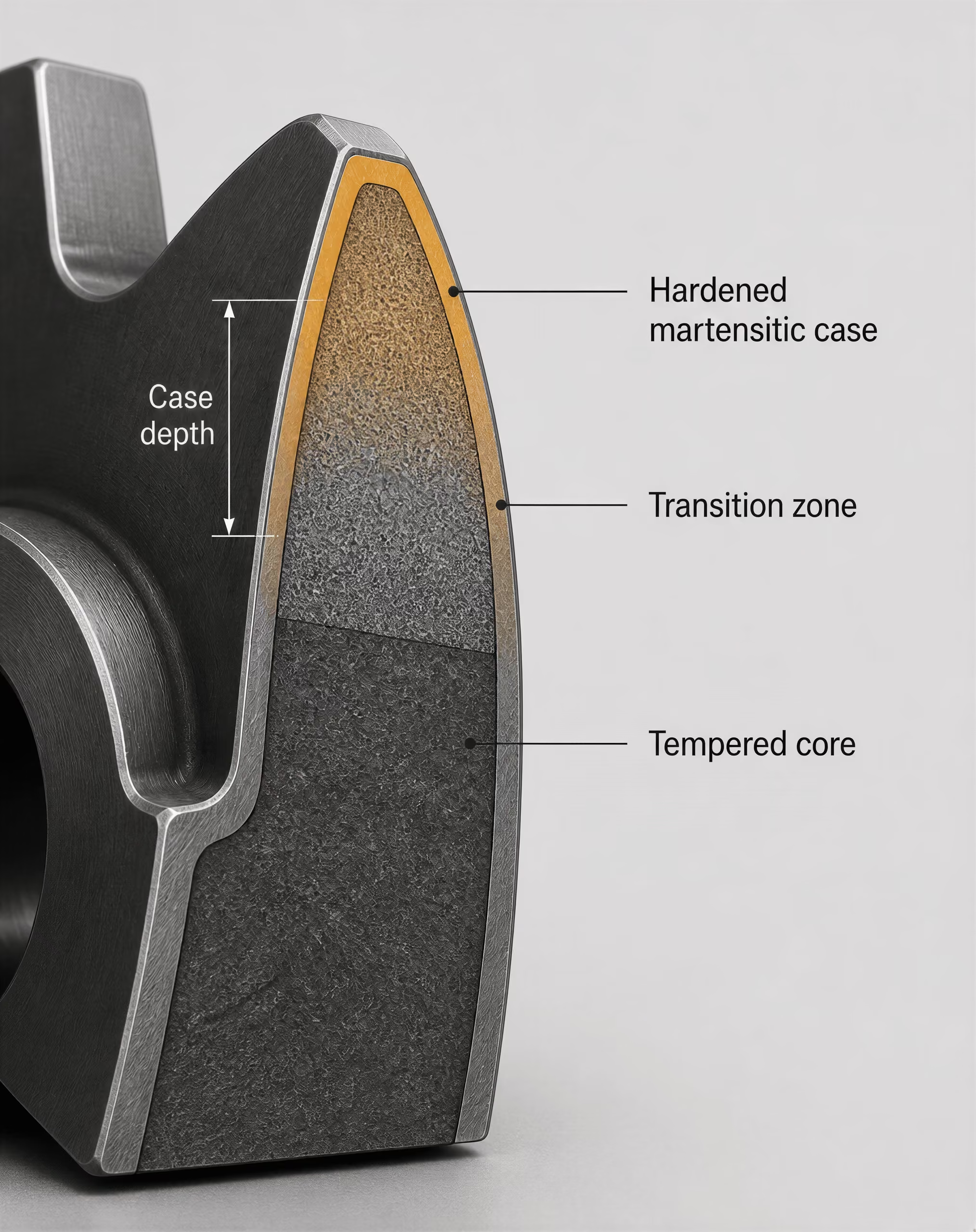
Surface versus core properties
The hardened case must be specified as a spatial profile. Surface hardness describes the first measurement location, but it does not state how far the hardened structure extends. Case depth may be defined by a metallographic boundary, a critical hardness, or an engineering criterion such as an effective case depth. Those definitions are not interchangeable. A surface reading of 60 HRC can coexist with a shallow case, a gradual transition, or a sharp hardness drop a short distance below the surface.
The core condition is equally important. A component may require a tough, tempered-martensitic core, a normalized ferrite-pearlite core, or a softer structure that can absorb strain without cracking. If a high-strength core is already present, localized heating must not temper or overheat adjacent regions. If the core has low hardenability, the quench may create a hard shell over a relatively soft interior. That may be acceptable for contact fatigue, but not for a part whose bending strength depends on the full section.
The transition zone deserves specific attention. It contains material that experienced austenitizing temperatures insufficient for complete transformation, or cooling rates too slow to form fully martensitic structure. Its hardness gradient controls strain compatibility between case and core. A steep gradient can concentrate stress; a broad gradient can reduce peak stress but may provide less wear resistance at depth. Tempering after hardening can reduce brittleness and stabilize the property profile, although it also lowers hardness. The selected cycle must account for tempering response, retained austenite, carbide precipitation, and dimensional change.
Surface hardness, effective case depth, transition-zone shape, residual stress, and distortion should therefore be evaluated together. A high compressive residual stress at the surface can improve resistance to bending fatigue, while tensile stress can promote crack initiation. The sign and magnitude depend on martensitic transformation strain, thermal contraction, section geometry, restraint, and quench timing. Hardness testing alone cannot reveal this stress state.
Thermal gradients and self-quenching
Localized hardening works because the heated layer and the cooler interior follow different thermal paths. During heating, the surface expands while the core restrains it. During cooling, the surface contracts first and may transform to martensite while the core is still hot. Martensite formation adds transformation expansion. These competing thermal and transformational strains generate residual stress and can produce bending, ovality, runout, or cracking.
Self-quenching occurs when the unheated mass of the component extracts heat from the austenitized layer rapidly enough to produce martensite without a separate external quench, or when that internal heat sink substantially assists a surface quench. It is most effective in thick sections with a cool core and high thermal conductivity. Thin sections, narrow projections, and previously hot components self-quench less strongly. External sprays are often added because self-quenching alone may not achieve the required cooling rate at every location.
The relevant cooling rate is not uniform through the case. The surface may cool rapidly by spray contact, while the case-to-core boundary cools through conduction and the core remains hot. Steel hardenability determines whether each location avoids the ferrite, pearlite, and bainite regions shown on continuous-cooling-transformation diagrams. Carbon content controls the hardness of the martensite; alloying elements shift transformation behavior; geometry controls heat flow.
Process qualification should map the actual part, not only a test coupon. Metallographic sections, hardness traverses, dimensional inspection, and residual-stress measurements can expose failures that a surface hardness check misses. ISO 17663:2023 places heat treatment performed in workshops or on site within a quality-requirements framework, mainly for ferritic steels and related welded or formed components. Its scope reinforces a practical point: temperature records, equipment control, calibration, cooling practice, and inspection belong to the treatment specification. Case-property design succeeds when the thermal cycle, microstructure, stress state, and dimensional result are treated as one connected problem.
Distortion, Residual Stress, and Cracking
Distortion is not a minor dimensional nuisance added to an otherwise successful heat treatment. It is one of the principal outcomes that must be predicted and controlled. ASM International’s 2024 chapter, “Basic Principles and Design Guidelines for Heat Treatment,” treats distortion and residual stress alongside phase transformations, rather than as afterthoughts to quenching. That emphasis is justified: a component may meet its hardness requirement yet fail because it bends, changes diameter, loses flatness, or contains tensile stresses that later initiate a crack.
Three related but different conditions must be separated. Distortion is a visible or measurable change in shape or dimensions. Residual stress is a self-equilibrating stress field remaining after external loads and thermal gradients have disappeared; it may exist without visible shape change. Quench cracking is actual fracture, usually caused when transformation and thermal stresses exceed the steel’s local strength and toughness. A part can therefore be straight but highly stressed, distorted without cracking, or cracked even when the final dimensional change appears small.

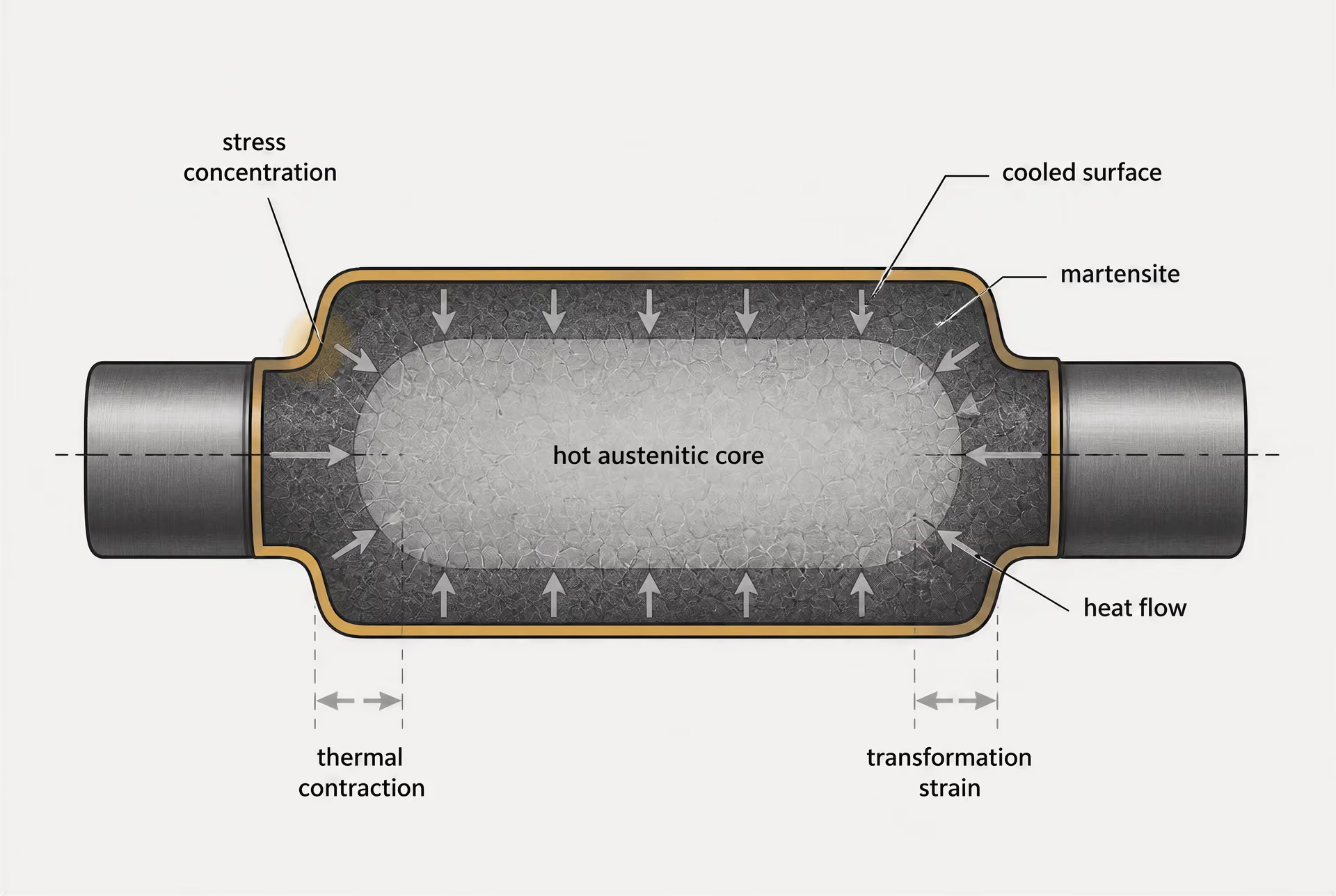
Thermal gradients and transformation strain
During heating, the surface of a steel component usually changes temperature before its core. The hotter region expands, while the colder interior restrains that expansion. If the surface reaches the austenitizing range first, its elastic and plastic response differs from that of the still-ferritic or pearlitic core. On cooling, the sequence reverses, but the stress pattern does not simply cancel because strength, thermal expansion, and phase stability are changing continuously.
Transformation strain adds a second source of dimensional change. Austenite has a different crystal structure and specific volume from ferrite, pearlite, bainite, and martensite. When austenite transforms, the component can expand or contract depending on the transformation product and carbon content. Martensite formation generally produces a volume increase, while the amount and timing of that increase depend on carbon in solution, alloy content, and the local cooling rate. A surface that reaches the martensite-start temperature while the core remains austenitic can expand against a core that is still contracting thermally. Later, the core transforms and changes the stress balance again.
The result is a moving contest between thermal contraction, transformation strain, and restraint. A thin edge may cool and transform quickly, gaining strength before the interior changes. A thick center may remain hot and relatively compliant, then transform later while the already hardened surface resists movement. Tensile residual stress at the surface is especially dangerous because cracks commonly begin there, at sharp corners, inclusions, decarburized zones, grinding marks, or other stress concentrators.
The iron–carbon diagram describes equilibrium phase relationships, but it cannot by itself predict this sequence. Transformation diagrams and actual continuous-cooling histories are required. The ASM treatment reference identifies time–temperature–transformation and continuous-heating/continuous-cooling transformation diagrams as tools for relating thermal history to phase formation. The same nominal quench can therefore produce different stress fields in a plain-carbon steel such as C45 and an alloy grade such as 42CrMo4 because hardenability changes where and when martensite forms.
Cracking requires more than a high hardness number. It depends on local tensile stress, the temperature-dependent strength and ductility of the steel, transformation timing, section geometry, surface condition, and metallurgical defects. Delayed cracking may occur after cooling when hydrogen, retained stress, and high-strength martensite act together. Tempering reduces some of the stresses and brittleness associated with as-quenched martensite, but it cannot restore material separated by a crack.
Geometry, fixturing, and quench access
Geometry controls both heat flow and mechanical restraint. Long slender shafts bend more readily than short, thick sections. A ring can change in roundness or grow in diameter. A plate with uneven thickness can dish because its two faces cool at different rates. Holes, keyways, grooves, threads, abrupt shoulders, and blind cavities disturb fluid flow and create local differences in cooling severity. A sharp re-entrant corner concentrates stress precisely where thermal and transformation strains are changing most rapidly.
Section size also determines whether the intended transformation occurs through the full thickness. A low-alloy steel may form martensite near the surface but bainite or pearlite toward the center if the core cools too slowly. That microstructural difference creates local variations in volume, hardness, strength, and subsequent tempering response. Dimensional change is then not merely a uniform scale change; it becomes a shape problem.
Fixturing can suppress one movement while forcing another. Clamping a plate flat during quenching may reduce bending during the operation, yet the released elastic energy can produce springback or twist afterward. A mandrel can preserve a bore temporarily while increasing hoop stress around it. Supports that contact only a few points may leave unsupported regions free to warp, while excessive restraint can raise cracking risk. Loads should be arranged so that parts are supported without blocking circulation or imposing unnecessary mechanical constraint.
Quench access must be considered as a geometric issue, not only a bath-selection issue. Surfaces facing one another, nested parts, blind holes, and tightly packed baskets may receive less fluid movement than exposed surfaces. Vapor blankets or trapped air can delay cooling at selected locations. Agitation must be sufficient to remove vapor and maintain a predictable cooling condition, but excessive or uneven agitation can magnify differences between orientations. The bath temperature, fluid condition, transfer time, and loading pattern all matter.
Design changes often reduce risk before a furnace cycle is selected. Generous radii replace sharp corners; thickness transitions are softened; holes and grooves are positioned to avoid severe local restraint; and machining allowances allow controlled removal of post-treatment distortion. No single geometry rule prevents every failure. A design that is safe for oil quenching may behave differently in water, polymer, salt, or gas.
Process controls for dimensional stability
Dimensional control begins with a thermal cycle that is repeatable throughout the load. Uniform furnace temperature, suitable support, controlled heating rate, and adequate soak time reduce differences between surface and core, although soaking too long can enlarge grains, increase oxidation, or worsen distortion through unnecessary exposure. Atmosphere control limits scale and decarburization, which otherwise alter surface hardness and dimensional response.
Transfer from furnace to quench must be rapid enough to preserve the specified thermal history and consistent from load to load. Load orientation should expose critical surfaces in a repeatable manner. Quench severity should match the steel’s hardenability and the required microstructure rather than being selected solely for maximum cooling rate. Suitable agitation and fluid circulation are essential, but their intensity and direction need monitoring because a nominally identical bath can cool different faces at different rates.
Staged or interrupted cooling can reduce the temperature difference between surface and core before the final transformation. Martempering, for example, holds steel near a temperature above or around the martensite-start range until temperatures equalize, then permits martensite to form more uniformly. Austempering uses a different transformation path, holding the steel to form bainite rather than cooling directly into the martensitic range. These methods can reduce distortion in suitable grades and geometries, but they do not remove the need to verify hardenability, section size, bath control, and transformation kinetics.
Tempering should follow quenching within the specified process window. For some components, a separate stress-relief treatment after rough machining or after an earlier thermal operation reduces the chance that residual stresses will be released during final machining. Stress relief is not a universal cure: it may change hardness, affect dimensional tolerances, or fail to remove stresses locked in by a severe quench.
Inspection must measure more than surface hardness. Depending on the component, dimensional checks may include length, roundness, straightness, flatness, bore size, and runout before and after treatment. Hardness traverses, metallographic examination, magnetic-particle inspection, and ultrasonic testing can reveal different classes of problems. ISO 17663:2023 places quality requirements on heat treatment in air or controlled atmospheres for ferritic steels and related welded or formed components, including work performed in workshops or on site. Its quality focus supports recorded furnace temperatures, transfer times, bath conditions, load identification, and inspection results.
Dimensional stability is therefore a design-and-process outcome. Uniform heating helps, controlled transfer helps, suitable agitation helps, and stress relief may help; none is sufficient in every case. The acceptable cycle is the one that produces the required phases and properties while keeping thermal strain, transformation strain, restraint, and residual stress within the component’s tolerance for distortion and fracture.
Heat Treatment in Welding and Fabrication
Heat treatment in fabrication begins before a furnace cycle is specified. Welding, flame cutting, forming, straightening, and local repair each impose thermal histories on steel, often over only part of a component. A weld arc may raise a narrow region above the austenitizing range while adjacent material remains relatively cool; heat then flows into the base metal, producing steep temperature gradients and uneven contraction. The resulting weld metal, fusion boundary, heat-affected zone (HAZ), and unaffected base metal can therefore have different microstructures, hardness levels, and residual stresses.
The outcome depends on composition, section thickness, restraint, joint geometry, heat input, preheat, interpass temperature, cooling conditions, and any later treatment. A recipe copied from a machined test piece cannot account for all of those variables.
Preheat, postweld heat treatment, and local thermal cycles
Preheating reduces the temperature difference between the weld region and the surrounding steel. That generally slows cooling after welding, allowing diffusible hydrogen more time to escape and reducing the likelihood of hydrogen-assisted cracking in susceptible steels. It also lowers thermal gradients and can reduce contraction-related stress. Preheat is not a universal safeguard: excessive temperature can enlarge the HAZ, alter toughness, increase distortion, or interfere with a specified welding procedure.
The relevant temperature is not simply the torch, induction coil, or arc temperature. It is the temperature of the workpiece at defined locations, including the area around the joint and, where applicable, the interpass region. Thickness, joint restraint, carbon content, alloying additions, and hardenability affect the cooling rate. A carbon-manganese steel and a low-alloy Cr-Mo steel may respond very differently to the same nominal preheat.
During welding, austenite can form in portions of the HAZ that exceed the critical transformation range. On cooling, that austenite may transform to ferrite, pearlite, bainite, or martensite, depending on the continuous-cooling path. Coarse grains may develop near the fusion boundary, while partially transformed or tempered regions occur farther away. These zones are not shown by the equilibrium iron–iron-carbide diagram alone. Time-temperature-transformation (TTT) diagrams describe isothermal behavior; continuous-heating and continuous-cooling transformation (CCT) diagrams are more useful for many real fabrication cycles.
Postweld heat treatment (PWHT) may temper hard transformation products, reduce residual stress, stabilize dimensions, and improve resistance to service damage. For a ferritic steel, the treatment can involve heating the welded component to a specified range, holding it long enough for the relevant section to reach the required condition, and cooling under controlled conditions. The actual cycle must come from the material specification, design code, welding procedure, or qualified engineering instruction. PWHT is not merely “stress relief,” because it can change hardness, toughness, strength, and microstructure.
Local PWHT is particularly sensitive to geometry. A band heated around a circumferential weld creates a moving thermal field, and the temperature outside the heated band must be controlled so that sharp thermal gradients do not introduce new stresses. Large vessels, pipelines, and field repairs may require multiple heating zones, insulation, controlled cooling, and several thermocouples. Furnace treatment can provide a more uniform environment, but loading, furnace calibration, support conditions, and the coldest part of the component still matter. A furnace does not guarantee uniform workpiece temperature.
The same principle applies to allied processes. Flame straightening deliberately creates local expansion and contraction; induction heating can harden a surface while leaving a steep transition beneath it; hot forming changes grain structure and residual stress; and thermal cutting can leave a hardened or softened edge. Each process should be treated as a defined thermal cycle rather than as an isolated temperature reading.
Ferritic steels and welded or formed components
Ferritic steels include many carbon, carbon-manganese, low-alloy, pressure-vessel, structural, and pipeline grades. Their response is governed by carbon and alloy content, prior grain size, section size, and cooling rate. The familiar phases named in the ASTM International Steel Metallurgy & Heat Treatment course—ferrite, austenite, cementite, pearlite, martensite, and bainite—are not interchangeable labels. They represent different arrangements and transformation products with different hardness, strength, toughness, and cracking behavior.
A weld can produce martensite in a rapidly cooled, hardenable HAZ even when the bulk plate remains ferritic-pearlitic. Tempering may reduce that hardness, but the result depends on the original composition and thermal exposure. Reheating a weld also affects previously deposited passes: a later pass can temper, refine, or partially transform material created by an earlier pass. In thick restrained sections, the surface and center may follow different cooling paths, so hardness and residual stress can vary through the thickness.
Formed components require the same attention. Bending, pressing, and local correction alter geometry and may produce work hardening, thinning, residual stress, or changes in grain flow. If a formed ferritic-steel part is subsequently welded, the prior forming history combines with the weld thermal cycle. Annealing, normalizing, quenching and tempering, or a specified stress-relief treatment may be appropriate in one design and damaging in another. ISO 683-1:2016 addresses technical delivery requirements for non-alloy steels intended primarily for quenching and tempering, austempering, flame hardening, induction hardening, and, in some cases, normalized conditions; it does not turn one treatment into a general instruction for fabricated assemblies.
ASM International’s 2024 ASM Handbook Volume 4A covers austenitizing, annealing, tempering, quenching, hardenability, surface hardening, austempering, martempering, hardness, and residual-stress control. Those subjects explain why a specified treatment must be tied to a grade and a component, not just to a furnace setpoint. Distortion is produced by both thermal expansion and transformation strain. Restraint determines how much of that movement becomes residual stress.
ISO 17663:2023 quality requirements
ISO 17663:2023 is the named quality-requirements standard for heat treatment connected with welding and allied processes. It covers treatment in air or controlled atmospheres, whether performed in workshops or on site, and applies mainly to ferritic steels and related welded or formed components. Its importance is procedural: the thermal cycle becomes a controlled manufacturing activity with defined responsibilities, equipment, measurements, records, and inspection.
A compliant quality system does not assume that a generic furnace program is adequate. The applicable procedure identifies the material, component, treatment purpose, heating method, temperature range, holding conditions, cooling method, and relevant measurement locations. Where the process is critical, procedure qualification demonstrates that the proposed cycle produces acceptable properties and dimensional results on representative material and geometry. Qualification may need to consider thickness, joint configuration, local heating arrangement, restraint, and the relationship between recorded air temperature and actual component temperature.
Temperature measurement is therefore a control function, not decoration on a chart. Thermocouples, sensors, recorders, and calibration status must be suitable for the process and positioned to detect significant hot and cold regions. Furnace or local-heating equipment requires control of uniformity, insulation, atmosphere where specified, heating rate, cooling rate, and protection against unintended contamination or oxidation. Local systems need particular attention to zone layout and heat loss at supports, attachments, and free edges.
Records establish what happened to the component. They can include material and weld identification, procedure revision, equipment identification, sensor locations, temperature-time charts, operator or inspector details, interruptions, repairs, and disposition of deviations. Traceability links those records to the heat number, weld number, assembly, or formed part. Inspection then compares the completed work with the applicable specification, including visual condition, dimensional checks, hardness, nondestructive examination, or mechanical testing when required by the governing design and manufacturing documents.
ISO 17663:2023 does not replace the material standard, design code, or welding procedure specification. It supplies a quality framework for controlling the treatment that those documents require. That distinction matters: successful fabrication is demonstrated by a controlled and traceable thermal history, followed by evidence that the finished component retains the required structure, properties, and dimensions.
Steel Grades, Specifications, and Standards Language
A steel designation and a heat-treatment condition identify different parts of the material record. The designation answers, “What steel grade was specified?” The condition answers, “How was that steel supplied or treated before it reached the next manufacturing operation?” Confusing those questions can turn a correct material callout into an incorrect process assumption.
A grade designation normally identifies a composition class or product category established by a standard. It does not, by itself, state that every part made from that grade has been quenched and tempered, nor does it guarantee a particular hardness after treatment. A delivery condition, by contrast, describes the state in which the material is supplied: for example, untreated, normalized, quenched and tempered, or otherwise processed under the applicable product specification. The exact permitted conditions and requirements depend on the standard, product form, and purchase specification.
Heat treatment adds a third layer. It is a controlled thermal cycle, not merely a named condition. Heating rate, austenitizing practice, holding time, cooling severity, atmosphere, temperature uniformity, part geometry, and section size all influence the resulting structure. Carbon and alloying elements affect phase stability and transformation kinetics; the same nominal grade can therefore respond differently when its dimensions, furnace loading, or cooling arrangement change.
ASM International’s 2024 ASM Handbook Volume 4A covers physical metallurgy, hardness and hardenability, quenching, annealing, tempering, austempering, martempering, austenitizing, and surface-hardening processes. Those subjects explain why a designation cannot replace a process specification. Ferrite, austenite, cementite, pearlite, martensite, and bainite form under different thermal and kinetic conditions. A steel’s designation supplies part of the starting information, while the treatment route determines which transformations are made possible and how uniformly they occur.
Non-alloy steels for quenching and tempering
Non-alloy steel is not synonymous with steel that can be processed by one universal hardening cycle. Its response depends on carbon level, prior microstructure, section thickness, heating practice, and cooling conditions. Quenching may produce martensite where the cooling rate is sufficient, while slower regions can transform into other products. Tempering then changes the as-quenched structure and relieves or redistributes stresses, but the final result still depends on the complete thermal history.
The relevant engineering question is therefore not simply whether a grade is “quenched-and-tempered steel.” It is whether the specified material, in its actual section and geometry, can achieve the required structure and properties under a defined route. Hardenability matters because hardness alone does not describe how deeply a section transforms. Distortion and residual stress matter because a component may meet a nominal hardness target yet fail dimensional or service requirements.
The equilibrium iron–iron-carbide diagram helps identify phase stability under near-equilibrium conditions, but it does not predict the result of a rapid quench by itself. Time-temperature-transformation diagrams describe isothermal transformation; continuous-heating and continuous-cooling transformation diagrams address changing temperature paths more directly. ASM’s 2024 treatment of steel heat treatment specifically connects these diagrams with austenitizing, transformation behavior, distortion, and residual-stress control. That connection is essential for non-alloy steels intended for hardening.
A normalized condition illustrates the distinction between grade and route. Normalizing can establish a different starting microstructure from an as-rolled or annealed condition, affecting subsequent austenitizing, quenching, and tempering behavior. It should be treated as a specified processing state, not as an automatic property of the designation.
Designation, delivery condition, and treatment route
A material callout should separate at least three questions: the identity of the steel, the condition in which it is delivered, and the treatment required for the component. The first may be expressed through a standard designation. The second may appear as a delivery condition in the product standard or order documentation. The third belongs in a process specification that defines how the component is heated, held, cooled, inspected, and accepted.
These records should also account for the component rather than only the furnace setpoint. A thin edge and a thick hub do not experience the same thermal history. Holes, corners, changes in section, and contact with fixtures alter heat flow and stress development. Furnace atmosphere can affect surface chemistry and scale formation; temperature uniformity and load arrangement affect whether all regions receive the intended cycle. Cooling media and agitation change heat extraction, while delayed transfer or uneven immersion can produce gradients.
The treatment name alone remains incomplete. “Quenched and tempered” identifies a sequence, but not the complete procedure. A usable process specification must establish the applicable grade and condition, equipment controls, temperature measurement, heating and holding rules, transfer requirements, cooling method, tempering practice, and inspection criteria. It may also need provisions for hardness mapping, dimensional checks, surface condition, and correction of distortion.
Standards define requirements and scope; they do not remove the need for engineering judgment about a particular component. ISO 17663:2023 provides a separate quality-requirements context for heat treatment connected with welding and allied processes. It covers treatment in air or controlled atmospheres, whether performed in workshops or on site, and applies mainly to ferritic steels and related welded or formed components. Its presence does not turn every heat-treatment operation into a welding procedure, but it shows why quality controls must follow the work being performed.
ISO 683-1:2016 in context
The exact title is ISO 683-1:2016, Heat-treatable steels, alloy steels and free-cutting steels — Part 1: Non-alloy steels for quenching and tempering. The title places non-alloy steels within a wider series while identifying the specific part covered by the document.
ISO 683-1:2016 defines technical delivery requirements within its stated scope, not a universal heat-treatment recipe. Strong evidence
According to the International Organization for Standardization, ISO 683-1:2016 specifies technical delivery requirements for non-alloy steels intended primarily for quenching and tempering, austempering, flame hardening, induction hardening, and, in some cases, normalized conditions. “Technical delivery requirements” is the important standards-language boundary. The document establishes requirements for material supplied under its scope; it does not constitute a universal recipe for every component made from a covered steel.
That distinction prevents two common errors. First, a designation covered by ISO 683-1:2016 does not prove that a finished component has received the required treatment. Second, selecting a delivery condition does not establish the complete thermal cycle needed to achieve a design objective. The component specification must still address geometry, section size, heating, holding, cooling, atmosphere, distortion control, residual stresses, and verification.
ISO 683-1:2016 is therefore a material and delivery reference within a larger control system. ASM International, ASTM International, NPTEL, and the 1984 reference Steel and Its Heat Treatment all describe heat treatment through phase transformations and time-temperature history. The standard supplies the contractual material framework; metallurgical analysis and a controlled process specification determine whether the actual part reaches the required condition.
Process Control, Verification, and Failure Analysis
Heat treatment should be verified as a controlled sequence, not judged by hardness alone. Before loading the furnace, confirm the steel grade, heat or cast number, product form, section size, and prior condition. A bar of quenched-and-tempered alloy steel is not interchangeable with a normalized carbon-steel bar, even when both carry similar carbon content. The starting ferrite-pearlite structure, prior cold work, grain size, segregation, and machining condition affect austenitizing response, transformation kinetics, distortion, and final hardness.
The process record should connect that material identity to the complete thermal history: furnace set point and measured temperature, atmosphere condition, load arrangement, heating rate where relevant, soak or hold time, transfer time, quench medium and agitation, cooling path, tempering cycle, and any post-treatment operation. ASM Handbook Volume 4A (ASM International, 2024) places hardness, hardenability, quenching, distortion, and residual-stress control within the same heat-treatment problem. That relationship matters. A part can reach a specified surface hardness and still contain an unsuitable core, excessive tensile stress, or a geometry change that prevents assembly.
ISO 683-1:2016 establishes technical delivery requirements for non-alloy steels intended primarily for quenching and tempering, austempering, flame hardening, induction hardening, and, in some cases, normalized conditions. ISO 17663:2023 addresses quality requirements for heat treatment in air or controlled atmospheres performed in workshops or on site, mainly for ferritic steels and related welded or formed components. These standards provide a quality framework; they do not turn every grade, geometry, and service condition into one universal acceptance rule. The applicable drawing, material specification, procedure, and inspection plan must define what is acceptable.
Furnace atmosphere and temperature uniformity
Temperature control begins with measurement rather than the controller display. A furnace may indicate 850 °C while the load experiences a different temperature because of sensor location, radiant gradients, damaged insulation, blocked circulation, or an overloaded working zone. Temperature-uniformity surveys and calibrated load thermocouples reveal these differences. The relevant question is not merely whether the furnace reached its set point, but whether the part reached the required temperature throughout the load and remained there for the intended time.
Load arrangement affects heating and cooling. Parts packed tightly together can shield one another from radiant heat and restrict gas or quench flow. Large cross sections heat more slowly at the center than at the surface; thin projections may overheat while the core is still below the intended austenitizing range. A holding time measured from furnace recovery may therefore be metallurgically different from a holding time measured after the load has equalized.
Atmosphere control serves two purposes: it limits chemical change at the surface and supports repeatable heat transfer. Excess oxygen or water vapour promotes oxidation and scale. A carbon potential below the steel’s equilibrium requirement can produce decarburization, removing carbon from the surface and reducing attainable hardness. Excess carbon potential can cause carburization, with a hard, brittle surface or an abnormal carbon gradient. Endothermic gas, nitrogen-methanol systems, vacuum, salt, and air each impose different monitoring needs. Dew point, oxygen potential, carbon potential, gas flow, pressure, and alarm records may be relevant, depending on the process.
Transfer from furnace to quench is another control point. Delay allows partial transformation, especially near the nose of a continuous-cooling-transformation diagram, and can produce ferrite, pearlite, or bainite before martensite formation is complete. Quench temperature, agitation, contamination, concentration, and part orientation then determine cooling severity. A quenchant that cools quickly at one location may cool slowly elsewhere because of vapour blankets, stagnant flow, or an altered fluid condition. The result is a process history, not a single cooling-rate number.
Hardness, microstructure, and dimensional checks
Verification should use several linked examinations. Hardness is a rapid screen for treatment response, but its meaning depends on location, method, surface condition, and section size. Check specified regions rather than only the most convenient surface. Compare surface and core where section thickness makes gradients likely, and remove scale or decarburized material when the inspection method requires a sound test surface. A hardness traverse can show whether induction or flame hardening produced the intended case depth, while a single reading may conceal an abrupt transition.
Microstructural examination explains hardness results that appear contradictory. After quenching, the structure may contain martensite, bainite, ferrite, pearlite, and retained austenite in proportions controlled by carbon content, alloying additions, cooling rate, and local geometry. Tempering changes martensite and relieves part of the quench stress; it does not erase every prior process error. Metallographic sections should be taken from representative or suspect locations, prepared without overheating or smearing, and interpreted with the steel grade and treatment history in view.
Surface inspection can identify oxidation, scale, decarburization, carburization, quench cracks, grinding cracks, laps, and local overheating. Decarburization commonly appears as a low-carbon ferritic layer beneath the surface. Oxidation leaves scale or intergranular attack when severe. Excessive retained austenite may accompany high carbon or alloy content, insufficient quench severity, an overly high quench temperature, or a martensite-start temperature low enough that transformation remains incomplete at room temperature. It can later transform during service, machining, or cold treatment, causing dimensional movement.
Dimensions require measurement before and after treatment at defined datums. Record length, diameter, flatness, roundness, runout, hole size, and relevant profile features according to the component drawing. Distortion is driven by unequal heating, transformation-volume changes, thermal gradients, asymmetric geometry, quench flow, machining residual stress, and restraints. Residual stresses can remain even when dimensions fall within tolerance, so distortion control and stress control are related but not identical tasks. ASM’s 2024 treatment of distortion and residual stresses is therefore directly relevant to inspection planning.
Interpreting nonconforming results
A nonconforming result is evidence of a process or material condition that requires separation and investigation, not an invitation to repeat the cycle without diagnosis. First preserve traceability: identify the furnace load, material heat, locations tested, instruments used, calibration status, and exact result. Confirm the test method and specimen location before assigning blame to metallurgy. A false low hardness reading can result from scale, decarburization, a rough surface, shallow indentation, or testing too near an edge.
Soft spots commonly arise from inadequate quench severity, poor agitation, vapour blanketing, blocked fluid flow, excessive transfer delay, insufficient austenitizing, or a section too large for the selected steel and quench. Nonuniform furnace temperature or an improperly arranged load can create the same appearance. Excessive hardness may indicate inadequate tempering, an incorrect tempering temperature, an over-carbonized surface, or a structure containing untempered martensite. It may also reflect a test taken on a thin hardened region rather than the intended bulk material.
Decarburization points toward atmosphere control, excessive exposure, scale removal, or a prior heating operation. Oxidation suggests air leakage, unsuitable furnace potential, high dew point, or prolonged exposure. Coarse grain usually follows excessive austenitizing temperature, excessive hold time, repeated heating, or local overheating; it can reduce toughness and increase distortion sensitivity. Cracking may result from severe quenching, sharp corners, grinding damage, pre-existing defects, hydrogen or surface contamination, or residual stresses that combine with transformation stress. Crack morphology and location are often more informative than hardness.
Unexpected retained austenite should prompt review of carbon and alloy content, actual austenitizing temperature, cooling rate, quench interruption, and any stabilizing effect from geometry or section thickness. Dimensional growth after treatment can support that diagnosis, but it is not proof by itself. Corrective action may involve reclassification, additional tempering, stress relief, reinspection, or rejection; the appropriate disposition depends on the governing specification and engineering assessment. The essential discipline is to change one identified process variable at a time and verify the resulting structure, properties, surface condition, and dimensions.
A Unified Framework for Selecting a Heat Treatment
Heat treatment should be selected from the required property profile and service conditions, not from a familiar temperature or a generic grade name. A controlled thermal cycle changes steel through phase transformations, but the resulting ferrite, pearlite, bainite, martensite, retained austenite, and carbides depend on composition, section size, heating rate, cooling path, and the starting condition of the material. The same nominal treatment can therefore produce useful toughness in one component and cracking, excessive distortion, or inadequate core hardness in another.
ASM International’s ASM Handbook Volume 4A identifies physical metallurgy, hardness and hardenability, quenching, annealing, tempering, austempering, martempering, austenitizing, and surface hardening as connected parts of steel heat treatment rather than isolated operations (ASM International, 2024). That connection is the basis for selecting a process.
Start with required properties and service conditions
Define the engineering target before choosing a thermal cycle. Required hardness may concern the whole section, a wear surface, or a narrow case depth. Tensile and yield strength matter, but they do not replace toughness, ductility, or fatigue resistance. A hard martensitic surface can resist abrasive wear while reducing tolerance to impact or increasing sensitivity to grinding damage. A lower-hardness bainitic or tempered-martensitic structure may carry repeated loads more reliably.
The service condition determines which compromise is acceptable. A gear tooth sees contact stress, sliding wear, bending fatigue, and often a hardness gradient from case to core. A shaft may need a tough core, a hard journal, and tight runout limits after treatment. A pressure-retaining welded component places greater emphasis on residual stress, hydrogen control, toughness, and inspection than on maximum hardness. Temperature, corrosive exposure, lubrication, impact loading, cyclic stress, and the consequences of fracture belong in the same initial assessment.
Dimensional tolerance must be specified alongside mechanical properties. A component held to a few hundredths of a millimetre cannot be treated as though distortion were a later correction. Geometry changes the thermal field: thin edges heat and cool rapidly, holes alter local stiffness, sharp corners concentrate stress, and long asymmetric sections bend as transformation strains develop. The desired surface/core gradient must also be explicit. Through-hardening, selective hardening, and stress-relieving treatments impose different thermal and mechanical demands.
The starting condition is part of the specification. Cast structure, prior cold work, normalized ferrite-pearlite, spheroidized carbides, previously tempered martensite, and a weld heat-affected zone do not respond identically. A welded component may contain hardness gradients and tensile residual stresses before the planned treatment begins. ISO 17663:2023 addresses quality requirements for heat treatment in air or controlled atmospheres, in workshops or on site, mainly for ferritic steels and related welded or formed components. Its relevance is practical: the process record, temperature measurement, atmosphere control, and inspection plan must match the component’s history and risk.
Match steel composition to transformation behavior
Carbon controls the amount of carbon available for martensite and affects the fractions and hardness of ferrite, pearlite, and cementite. Alloying elements alter transformation temperatures, carbide stability, hardenability, tempering response, and oxidation behavior. AISI 1045 and AISI 4140 cannot be assigned the same quench assumption merely because both can be quenched and tempered. The chromium-molybdenum content of AISI 4140 delays diffusional transformations and generally permits greater through-hardening than plain-carbon AISI 1045 in a comparable section. AISI 52100 adds high carbon and chromium, with carbide control becoming central to bearing performance and dimensional stability.
The iron–iron-carbide diagram helps identify equilibrium phases and carbon solubility, but it does not predict the structure formed by a real cooling cycle. Austenite can transform to pearlite or bainite if cooling intersects the relevant time-temperature region; if diffusion is suppressed sufficiently, it can transform to martensite at temperatures governed by the steel’s composition. ASM’s 2024 treatment of transformation diagrams distinguishes equilibrium concepts from time-temperature-transformation (TTT) and continuous-cooling-transformation (CCT) behavior. That distinction prevents a common error: choosing an austenitizing temperature from a phase diagram and assuming the cooling result is thereby fixed.
Use a TTT diagram to reason about isothermal holds and a CCT diagram to reason about practical cooling from austenite. The question is not simply whether a quenchant is “fast.” It is whether the cooling curve for the actual section avoids the pearlite or bainite nose where necessary, then passes through the martensitic range at a rate that limits thermal and transformation stress. A large diameter may cool slowly at its centre while a thin edge cools rapidly, producing different structures in one part. Hardenability, tested for example by the Jominy end-quench method, describes the depth to which a steel can develop hardness under a defined cooling condition; it does not guarantee a particular hardness in every geometry.
This reasoning can lead away from maximum quench severity. Quenching and tempering may provide the required strength, but martempering can reduce the temperature difference during martensite formation and thereby lower distortion risk. Austempering may produce bainite with useful toughness and reduced quench strain when the steel and section size permit the required isothermal transformation. Normalizing can refine an uneven prior structure, while annealing or spheroidizing can improve machinability before hardening. Flame and induction hardening can place high hardness at the surface while retaining a tougher core, provided the heating pattern, frequency, scan speed, and self-quenching capacity are controlled.
Balance performance, manufacturability, and risk
A technically attainable microstructure may still be a poor manufacturing choice. Consider furnace capacity, load arrangement, heating uniformity, quench agitation, quenchant contamination, atmosphere, fixturing, machining sequence, and the ability to measure temperature at representative locations. Atmosphere selection is not cosmetic: oxidation, decarburization, carburization, and scale can alter surface hardness and dimensions. A hardenability calculation is also incomplete without section thickness, corner radii, contact with fixtures, and the cooling conditions at the surface.
Residual stress and distortion must be treated as design constraints. Thermal contraction and transformation expansion occur at different times and locations, while martensite formation can lock in stresses before the core has cooled. Cracks are more likely when high stress combines with high hardness, sharp geometry, surface damage, hydrogen, or an unsuitable quench. Tempering is therefore not merely a hardness adjustment; it changes the stability and toughness of the as-quenched structure and reduces part of the quench-stress burden. Tempering temperature, time, and transfer delay require control.
Welding history can change the decision entirely. Post-weld heat treatment may reduce residual stress or temper hard zones, but it can also affect strength, dimensional accuracy, and toughness if the cycle is poorly matched to the steel. ISO 683-1:2016 covers technical delivery requirements for non-alloy steels intended primarily for quenching and tempering, austempering, flame hardening, induction hardening, and, in some cases, normalized conditions. The standard does not remove the need to qualify a treatment for a particular part.
Inspection capability sets the boundary of credible process control. Hardness surveys should address surface and core where a gradient is specified. Metallography may be needed to detect decarburization, retained austenite, untempered martensite, bainite, carbide networks, or an abnormal grain size. Dimensional checks, magnetic-particle or dye-penetrant inspection, ultrasonic testing, and residual-stress assessment may be appropriate when cracking or internal defects carry serious consequences.
Selecting a treatment
- Define the target Set service loads, property limits, surface/core requirements, and dimensional tolerances.
- Identify the starting state Confirm grade, prior microstructure, section geometry, product form, and welding history.
- Assess kinetics Use suitable TTT or CCT information for the actual steel and thermal path.
- Choose the route Select heating, atmosphere, cooling, tempering, or surface-hardening methods that can be controlled.
- Qualify and verify Check hardness, microstructure, dimensions, surface condition, and defects against the applicable specification.
The selection decision can therefore be made in sequence: define service loads and property limits; specify surface/core hardness and dimensional tolerances; identify grade, prior microstructure, section geometry, and welding history; compare TTT/CCT transformation paths; select heating, atmosphere, cooling, and tempering methods that can be controlled; then qualify the cycle through hardness, structure, dimensions, and defect inspection. If no single path meets strength, toughness, distortion, and production limits, change the steel, geometry, machining sequence, or surface-treatment strategy. Heat treatment is a coupled metallurgy-and-process problem. The controlling choice is not one temperature number, but a verified thermal history matched to the steel and the part.
References
- [1] Steel Heat Treating—Fundamentals and Processes. ASM Handbook Volume 4A, 2024. https://dl.asminternational.org/handbooks/edited-volume/18/Steel-Heat-Treating-Fundamentals-and-Processes
- [2] Steel Metallurgy & Heat Treatment course outline. ASTM International course outline, 2024. https://store.astm.org/astm-tpt-727.html
- [3] Fundamentals of the Heat Treating of Steel. ASM technical monograph, 2024. https://dl.asminternational.org/technical-books/monograph/99/chapter-abstract/2112447/Fundamentals-of-the-Heat-Treating-of-Steel
- [4] ISO 17663:2023. International standard, 2023. https://www.iso.org/standard/83142.html
- [5] Basic Principles and Design Guidelines for Heat Treatment. ASM Handbook chapter, 2024. https://dl.asminternational.org/handbooks/edited-volume/49/chapter-abstract/608501/Basic-Principles-and-Design-Guidelines-for-Heat
- [6] Steel and Its Heat Treatment. Technical reference, 1984. https://www.sciencedirect.com/book/9780408014243/steel-and-its-heat-treatment