


What Bearing Steels Must Resist
Rolling contact rather than simple sliding wear
A bearing raceway does not merely support a stationary compressive load. A rolling element repeatedly enters and leaves contact with the inner ring, outer ring, or both, while the contact zone travels through the steel at every revolution. The load is concentrated over a small, curved area, so the local pressure is high even when the bearing’s externally applied load appears modest. The contact is predominantly elastic: the raceway and rolling element deform slightly under load, form a Hertzian contact area, and recover their shapes as the contact moves away.
That repeated elastic loading separates rolling-contact service from simple sliding wear. Sliding wear is governed mainly by relative motion at an interface, friction, adhesion, abrasion, and removal of surface material. A rolling bearing can experience little macroscopic sliding and still fail through fatigue below the visible surface. Some sliding does occur, especially from spin, skew, differential curvature, or inadequate kinematics, but it is superimposed on repeated concentrated contact rather than replacing it.
The raceway and rolling element also share the load unevenly. Bearing geometry, internal clearance, misalignment, ring deformation, and load direction determine which elements carry the greatest forces. SKF’s treatment of contact geometry and load distribution therefore places stress calculation alongside material condition and lubrication. A nominally identical bearing can develop very different local stresses if mounting, shaft deflection, housing distortion, or contamination changes the load distribution.
Damage terms
- Wear
- Removal or displacement of material through surface interaction.
- Plastic deformation
- Permanent dents, ridges, or flattened regions formed when local pressure exceeds yield resistance.
- Micropitting
- Small surface-fatigue pits associated with roughness, inadequate lubricant film, and asperity stress.
- Rolling-contact fatigue
- Progressive crack initiation and growth under repeated rolling stress, often followed by spalling.
Several damage terms should not be treated as synonyms. Wear removes or displaces material through surface interaction. Plastic deformation produces dents, ridges, or permanently flattened regions when contact pressure exceeds the local yield resistance, often after debris passes through the contact. Micropitting consists of very small surface fatigue pits associated with roughness, lubricant-film deficiency, and local asperity stress. Rolling-contact fatigue is the progressive initiation and growth of cracks under repeated rolling stress; it may begin beneath the surface and later produce spalling at the raceway.
A dent from a hard particle is therefore not the same event as a fatigue spall, even though the dent can become a stress raiser that accelerates one. Similarly, a polished-looking raceway may still contain subsurface damage. Surface appearance alone cannot establish how much fatigue life remains.
High-carbon chromium bearing steel is a standard material for rolling elements and raceways, according to NTN. A familiar designation is AISI 52100, commonly corresponding to 100Cr6 in European bearing-steel practice. The designation identifies a chemistry and product class; it does not guarantee identical cleanliness, carbide distribution, heat treatment, residual stress, or service life.
Subsurface stress and material fatigue

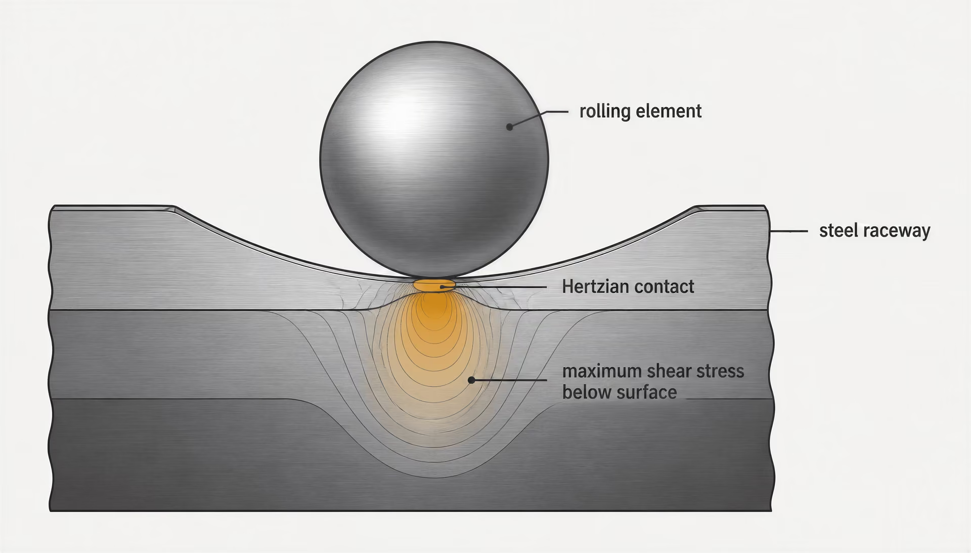
As an elastic contact passes over the raceway, the maximum shear stress is usually located below the surface rather than exactly at it. Each material volume experiences a sequence of compression, shear, and stress reversal as the rolling element approaches, passes over, and departs. Repetition can nucleate a crack at a nonmetallic inclusion, carbide cluster, pore, surface defect, or region of unfavorable microstructure. The crack may grow toward the surface until a fragment breaks away, producing a flake or spall.
Hardness alone is an incomplete predictor of rolling-contact-fatigue life. Strong evidence
[1] Bearing Steels. NASA. NASA Technical Reports Server, 1987.This is why hardness by itself is a poor predictor. Higher hardness can improve resistance to plastic indentation and may support a high load rating, but hardness does not describe the size and spacing of inclusions, the morphology of carbides, retained austenite, prior-austenite grain size, residual stresses, or the toughness available to resist crack growth. NASA reported in 1987 that bearing-steel hardness, retained austenite, grain size, and carbide size, number, and area all influence rolling-element fatigue life. Its findings also indicate that processing, including double-vacuum melting, can affect life more strongly than chemistry alone.
| Steel architecture | Hardness profile | Core condition | Typical design purpose |
|---|---|---|---|
| Through-hardened martensitic | Hard through the working section | Predominantly hardened section | High resistance to repeated contact stress |
| Through-hardened bainitic | Hard through the working section | Bainitic working structure | Hardness, toughness, and dimensional stability |
| Case-hardened | Hard surface layer | Softer, tougher core | Surface fatigue resistance with shock tolerance |
The 2011 review Steels for bearings separates the principal material families into through-hardened martensitic or bainitic steels and case-hardened steels, which have a hard surface layer over a softer core. These architectures distribute stress differently. Through-hardened steels provide high hardness through the working section; case-hardened steels can combine a fatigue-resistant surface with a tougher core that tolerates subsurface stress and shock. Neither arrangement removes the need for suitable cleanliness and heat treatment.
The ASM Handbook’s 2014 treatment of bearing steels makes the point directly: after suitable microstructure has been achieved, steel cleanliness and freedom from harmful nonmetallic inclusions are the single most important factor in obtaining high rolling-contact-fatigue life. An inclusion acts as a local mismatch in stiffness and a stress raiser. Its effect depends on size, shape, location, orientation, and distance from the maximum stressed region. Two components made to the same grade designation can therefore show different fatigue lives if their inclusion populations differ.
ASTM STP 1327 places this issue within the wider technical context of bearing life, rolling-contact fatigue, steelmaking, through-hardening, case-hardening, aerospace steels, corrosion-resistant steels, and surface modification. The material grade matters. It is not the complete fatigue model.
Why a bearing is a coupled material-and-lubrication system
Lubrication changes the stresses imposed at the contact. A sufficiently thick elastohydrodynamic film separates most opposing asperities and distributes load across a larger effective contact region. If the film becomes too thin because of low viscosity, high temperature, inadequate supply, surface roughness, or excessive speed and load, asperity interactions add local friction and stress. SKF consequently treats lubrication, contamination, contact geometry, load distribution, and stress raisers as connected parts of fatigue assessment rather than separate maintenance topics.[2] Effects of Water Contamination on Micropitting and Rolling Contact Fatigue of Bearing Steels. U.S. Department of Energy, Office of Scientific and Technical Information. OSTI, 2024.
Contamination can damage the system in two ways. A hard particle may indent a raceway, creating a permanent geometric defect that repeatedly interrupts the contact. Water can alter lubricant behavior, promote corrosion or hydrogen-related effects, and change crack initiation conditions. Experimental work reported through the U.S. Department of Energy in 2024 found that dissolved or free water increased micropitting and rolling-contact-fatigue cracking and was associated with white-etching matter at crack interfaces. A clean steel with poor lubricant control is not operating under the conditions implied by its material specification.
Bearing life calculations also require a precise statistical definition. ISO 281:2007 specifies methods for dynamic load ratings and basic rating life for rolling bearings manufactured from high-quality hardened bearing steel; BS ISO 281:2007 is the British adoption. Its basic rating life is associated with 90% reliability. Schaeffler defines L10 as the number of revolutions reached or exceeded by 90% of apparently identical bearings before the first indications of material fatigue appear. JTEKT likewise describes the basic dynamic load rating as rolling-fatigue capacity and L10 as the 90%-reliability life for bearings made from specified bearing steels or equivalent materials.
That figure is not a promise that every bearing will run until the same revolution count, nor does it describe every failure mode. Adjusted life calculations introduce factors for lubrication, contamination, reliability, and fatigue-limit load. Seal damage, electrical erosion, false brinelling, corrosion, mounting error, and overload may end service before classic subsurface fatigue does.
The central engineering fact follows: a grade designation can establish a starting material category, but it cannot by itself predict service life. Rolling-contact fatigue is the response of a coupled system—steelmaking, microstructure, heat treatment, geometry, load distribution, lubrication, contamination, and operating history—observed through a statistical definition of bearing life.
How ISO 281 Defines Bearing Life
ISO 281:2007 is a calculation standard for rolling bearings, not a promise that an individual bearing will operate for a specified number of hours. Its British adoption, BS ISO 281:2007, has the same role. The standard provides methods for calculating dynamic load ratings and rating life for bearings manufactured from high-quality hardened bearing steel or equivalent materials under defined operating conditions.
That distinction matters because calculated life is often presented as though it were a material guarantee. It is not. A bearing can fail before its calculated life because of contamination, inadequate lubrication, mounting damage, electrical erosion, excessive misalignment, manufacturing variation or an inclusion that becomes a fatigue origin. It can also run far beyond the calculated value. ISO 281 describes a statistical population, not the certain service duration of one ring and rolling-element set.
The calculation therefore links material capability with contact loading and operating conditions. Steel cleanliness, microstructure, residual stress, retained austenite, carbide morphology and surface condition establish part of that capability; contact geometry, load distribution, lubricant film and contaminants determine how much of it is available in service.
Dynamic load rating and basic rating life
Basic dynamic load rating A calculated measure of a bearing's rolling-contact-fatigue capacity under the conditions defined by the rating method; it is not the maximum static load.
The basic dynamic load rating, normally designated C, is a calculated measure of a bearing’s rolling-contact fatigue capacity. It is not the maximum load that the bearing can carry without deformation, nor is it a simple tensile-strength value for the steel. In the ISO framework, C is related to the constant load and direction that a group of apparently identical bearings can sustain for a basic rating life of one million revolutions.
Equivalent dynamic load A calculated load, commonly designated P, that combines relevant radial and axial loading for the bearing-life equation.
The applied load is converted into a bearing-specific equivalent dynamic load, usually designated P, so that radial and axial components can be assessed together. For a bearing under predominantly rolling-contact fatigue, the basic rating-life relationship is commonly expressed as:
where is expressed in millions of revolutions and depends on the rolling-element type: for ball bearings and for roller bearings in the standard life relationship. Manufacturers’ catalogues apply the appropriate ISO equations, load factors and internal geometry to particular bearing designs.
The exponent makes load control especially important. A modest increase in equivalent load can produce a much larger reduction in calculated life, even though the steel chemistry and nominal hardness have not changed. Conversely, increasing hardness does not automatically produce the corresponding increase in life if a bearing contains harmful nonmetallic inclusions or operates with a damaged lubricant film.[3] Bearing Steels. ASM International. ASM Handbook, 2014.
This is why bearing steel cannot be judged by hardness alone. The 2014 ASM Handbook identifies steel cleanliness and freedom from harmful nonmetallic inclusions as the single most important factor, after suitable microstructure, in achieving high rolling-contact-fatigue life. The 2011 review Steels for bearings separates the principal material families into through-hardened martensitic or bainitic steels and case-hardened steels with a hard surface layer over a softer core. Both designs can provide the required contact strength, but inclusions and processing defects can still initiate subsurface fatigue.
NASA reported in 1987 that hardness, retained austenite, grain size, and carbide size, number and area influence rolling-element fatigue life. Its findings also show why processing history matters: methods such as double-vacuum melting can affect fatigue performance more strongly than a small change in nominal alloy chemistry. High-carbon chromium bearing steel remains a standard material for rolling elements and raceways, as NTN states, but the designation of the alloy does not by itself establish the life of a finished bearing.
The meaning of L10 and 90% reliability
ISO 281 basic rating life is associated with 90% reliability. Strong evidence
[4] ISO 281:2007 Rolling bearings — Dynamic load ratings and rating life. International Organization for Standardization. International Standard, 2007.ISO 281 defines the basic rating life as the life associated with 90% reliability. This life is designated L10, although the notation can mislead readers who interpret “10” as a ten-percent service limit. It is not a failure deadline.
- Reliability basis
- 90%
- Population
- Apparently identical bearings
- Event
- First indications of material fatigue
- Interpretation
- 90% reach or exceed L10
Schaeffler defines L10 as the number of revolutions reached or exceeded by 90% of apparently identical bearings before the first indications of material fatigue appear. JTEKT gives the same statistical meaning and states that its basic dynamic load rating represents rolling-fatigue capacity for bearings made from specified bearing steels or equivalent materials. Thus, in a population tested under the assumptions of the calculation, ten percent may show the first material-fatigue indications before L10, while ninety percent reach or exceed it.
“First indications” is also significant. The event is the onset of rolling-contact fatigue, such as subsurface crack development or the resulting flaking, not necessarily complete seizure, fracture or loss of all load-carrying ability. A bearing that has reached L10 is not automatically unusable, and a bearing that has not reached L10 is not immune from failure through another mechanism.
Nor is L10 the average life. Bearing-life distributions are scattered, so the arithmetic mean can be substantially higher than the 90%-reliability life and can be distorted by a small number of long-running bearings. L10 is used because it gives a defined lower-tail population measure that engineers can apply consistently. Reliability calculations above 90% require a separate reliability adjustment; they should not be inferred by simply multiplying L10 by a chosen percentage.
The statistic also assumes a population of apparently identical bearings operating under the relevant load, speed, lubrication and material conditions. Real production bearings are never perfectly identical, and real machines rarely maintain constant conditions. The calculated figure therefore has meaning only alongside its assumptions.
Basic life versus adjusted rating life
Basic rating life uses the ISO reference conditions and is principally a load-and-fatigue calculation. Adjusted rating life extends that calculation by accounting for factors that can raise or reduce fatigue life under the actual application. ISO 281 includes the effects of reliability, lubrication, contamination and the fatigue-limit load. These influences are not interchangeable with hardness and are not safely represented by an unsupported universal correction factor.
Lubrication affects the separation between contacting asperities and therefore the severity of local stress concentrations. A sufficient elastohydrodynamic film can reduce damaging surface interaction; a thin or degraded film can promote micropitting and accelerate crack initiation. Contamination introduces indentations and stress raisers, while water can alter both the lubricant and the steel surface. A 2024 U.S. Department of Energy report found that dissolved or free water increased micropitting and rolling-contact-fatigue cracking and was associated with white-etching matter at crack interfaces.
Contamination adjustment also depends on the type, size, concentration and distribution of particles, as well as bearing size and contact conditions. It cannot be reduced to the statement that a bearing is “clean” because its steel met a material specification. Internal cleanliness remains important: the ASM Handbook’s assessment places harmful inclusions immediately after microstructure in importance for high fatigue life.
The fatigue-limit load, commonly associated with Pu, represents the load below which subsurface fatigue is treated differently in the adjusted-life model. It does not mean that any load below Pu guarantees indefinite operation. Surface distress, wear, corrosion, electrical damage, false brinelling and lubricant failure can occur without the classic subsurface fatigue process assumed by the basic rating equation.
Adjusted rating life is therefore a model of a bearing system: steelmaking and heat treatment, bearing geometry, applied load, lubrication, contamination and required reliability all enter the result. ISO 281 supplies a disciplined calculation method. It does not replace failure analysis, cleanliness control, lubricant monitoring or sound bearing design, and it cannot turn a nominal hardness value into a guarantee of service life.
The Principal Families of Bearing Steel
The review Steels for bearings (2011) and ASTM STP 1327 place bearing steels into two principal families: through-hardened steels, which are martensitic or bainitic throughout the working section, and case-hardened steels, which have a hard surface layer over a tougher, softer core. This is a metallurgical classification, not a ranking. The correct choice depends on contact stress, section size, shock loading, geometry, manufacturing route and the required damage tolerance.
Bearing life cannot be inferred from nominal hardness alone. ISO 281:2007 calculates dynamic load ratings and basic rating life for rolling bearings made from high-quality hardened bearing steel, with basic rating life defined at 90% reliability. The designation L10 therefore means that 90% of apparently identical bearings are expected to reach or exceed the stated number of revolutions before the first indications of material fatigue; it does not mean that every bearing will fail at that point. Schaeffler and JTEKT use this same definition. Adjusted life can account for lubrication, contamination, reliability and fatigue-limit load, all of which can move actual performance away from a simple material-based estimate.
Through-hardened martensitic steels
| Feature | Through-hardened steel | Case-hardened steel |
|---|---|---|
| Carbon distribution | Designed for the working section | Enriched near the surface |
| Hard region | Extends through the useful section | Concentrated in the case |
| Core | Hardened working structure | Lower-carbon, tougher structure |
| Main processing route | Austenitizing, quenching, tempering, or bainitic transformation | Carburizing or carbonitriding followed by hardening and tempering |
A through-hardened steel is not merely a hard steel. After austenitizing and quenching, the intended cross-section transforms to martensite, followed by tempering to establish the required hardness, dimensional stability and residual-stress condition. “Through” describes the depth of the hardened structure; it does not require every atom of the part to have identical carbon content or identical hardness. In a bearing ring or rolling element, the relevant region must retain a suitable tempered-martensitic structure under the operating contact.
| Designation system | Designation | Material description |
|---|---|---|
| AISI | 52100 | High-carbon chromium bearing steel |
| SAE | 52100 | High-carbon chromium bearing steel |
| European | 100Cr6 / 1.3505 | High-carbon chromium bearing steel |
| JIS | SUJ2 | High-carbon chromium bearing steel |
The familiar high-carbon chromium grade AISI 52100, also designated SAE J404 52100, EN ISO 683-17 100Cr6 and JIS G 4805 SUJ2, is the standard example. NTN identifies high-carbon chromium bearing steel as a standard material for rolling elements and raceways. Its approximately 1% carbon and 1.5% chromium support high hardness, wear resistance and carbide formation, but the grade name does not guarantee fatigue life. Carbide size, distribution and dissolution during heat treatment matter. Excessive or poorly distributed carbides can act as local stress raisers or leave compositional variation after austenitizing.
Hardenability The ability of a steel section to develop the intended hardened transformation structure at a given cooling rate.
Hardenability determines how far from the quenched surface the steel can develop the intended martensitic structure at a given cooling rate. In a small ball, a conventional high-carbon chromium steel may harden through most of the section readily; in a large ring, cooling conditions and section thickness can produce different transformation products or hardness gradients. That distinction matters because rolling-contact fatigue is driven by a subsurface, cyclic shear-stress field, not by the surface hardness number alone.
Retained austenite is another controlled variable. Some retained austenite can accommodate transformation strains and contribute to dimensional stability when properly selected, while excessive or unstable retained austenite may transform during service, changing dimensions and generating local stresses. NASA’s 1987 review identifies hardness, retained austenite, grain size, and carbide size, number and area as factors affecting rolling-element fatigue life. Fine prior-austenite grains and a controlled carbide population generally reduce dangerous local variations, but “more hardness” remains an incomplete design rule.
The ASM Handbook (2014) gives cleanliness and freedom from harmful nonmetallic inclusions its strongest warning: after suitable microstructure, cleanliness is the single most important factor in achieving high rolling-contact-fatigue life. An inclusion can initiate a crack below the raceway even when hardness, chemistry and measured case depth appear correct. Vacuum processing, electroslag remelting where appropriate, forging practice, reduction ratio and inspection can therefore influence life more than a small adjustment in alloy content. The materials study context in ASTM STP 1327 includes steelmaking, cleanliness, rolling-contact fatigue and through-hardening for this reason.
Bainitic steels form the second through-hardened branch. Their transformation route differs: instead of quenching directly to predominantly martensite and tempering, the steel is cooled and held within a bainitic transformation range, or processed through a controlled heat-treatment schedule that produces a bainitic matrix. Bainite can offer a useful combination of hardness, toughness, dimensional stability and residual stress, particularly in large sections where direct quenching may create unwanted gradients. Its performance still depends on carbide morphology, prior austenite grain size, retained austenite, inclusion content and the exact transformation schedule. “Bainitic” is not a substitute for specifying the structure and processing condition.
Case-hardened steels with a softer core
Case-hardened steels place the highest carbon content, and therefore the highest attainable hardness, near the working surface. Carburizing or carbonitriding enriches the outer layer before quenching; the case transforms to hard martensite, often with controlled retained austenite, while the lower-carbon interior develops a tougher, lower-hardness core. Common engineering examples include EN ISO 683-3 20MnCr5 and SAE J404 8620, although the applicable designation and heat-treatment specification must be stated for the component rather than assumed from a family label.

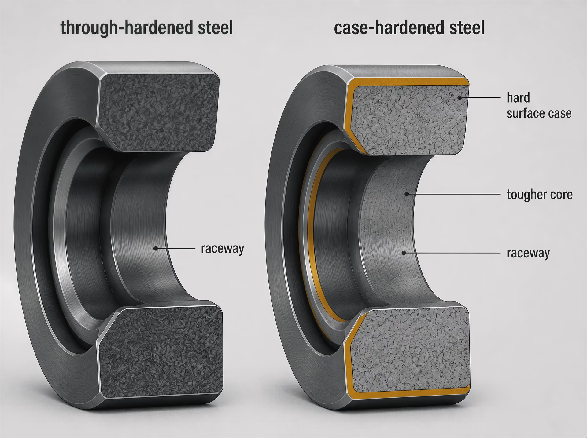
The surface layer must resist plastic deformation, wear and rolling-contact fatigue. Its depth must also extend beyond the zone where damaging contact stresses are concentrated, with a transition that does not create a sharp weakness. The core has a different assignment: it must support the case, absorb shock, resist fracture and tolerate stresses from press fits, impact or misalignment. A case-hardened bearing can therefore accept a harder working surface without making the entire section as brittle as a fully high-carbon, high-hardness structure might become.
Core toughness is especially important for large rings, heavily loaded components and applications exposed to impact or edge loading. Yet a tough core cannot compensate for a contaminated case, inadequate case depth, excessive retained austenite or grinding damage. Carbon gradients, quench severity, distortion and residual stresses must be controlled together. The case is also not automatically superior in rolling fatigue: if the contact stress penetrates deeply, if the transition is poorly designed, or if an inclusion lies in the critical subsurface region, the intended advantage can disappear.
The two families also respond differently to hardenability. In a through-hardened grade, hardenability controls whether the working section develops the required martensitic structure throughout. In a case-hardened grade, it controls the transformation of both the enriched case and the low-carbon core, while carburizing controls carbon depth and gradient. Surface hardness can be similar between the families, but their subsurface stress response and fracture behavior are not the same.
Finally, neither family operates in isolation from the bearing system. SKF relates fatigue damage to contact geometry, load distribution, lubrication and stress raisers. The 2024 U.S. Department of Energy study on water contamination found that dissolved or free water increased micropitting and rolling-contact-fatigue cracking and was associated with white-etching matter at crack interfaces. Material capability sets a ceiling; cleanliness, processing, assembly, lubricant condition and contamination determine how much of that capability is reached.
High-Carbon Chromium Bearing Steel and Common Designations
The role of high carbon and chromium
High-carbon chromium steel is a material family used for many rolling-bearing rings and rolling elements, but its designation does not by itself predict bearing life. NTN identifies high-carbon chromium bearing steel as a standard material for rolling elements and raceways in its 2020 bearing documentation. That statement describes a recognized material category, not a claim that one grade is used for every bearing, load case, or operating environment. Through-hardened martensitic and bainitic steels form one major bearing-steel class; case-hardened steels, with a hard surface layer over a tougher core, form another, as described in the 2011 review Steels for bearings.
Carbon supplies the hardening response needed for a through-hardened bearing steel. During austenitizing and quenching, sufficient carbon permits formation of high-carbon martensite, while undissolved and precipitated carbides contribute to wear resistance and contact-strength capability. The amount and distribution matter. Excessive carbide segregation, coarse carbide particles, or an unsuitable carbide network can create local stress concentrations rather than improve fatigue performance.
Chromium serves several related purposes. It increases hardenability, allowing a bearing section to transform more uniformly during quenching, and it participates in chromium-rich carbide formation. It also supports the dimensional stability and wear resistance expected from the heat-treated structure. Yet chromium content is not a substitute for a controlled process. Austenitizing temperature, holding time, cooling rate, tempering, retained austenite, prior-austenite grain size, and carbide morphology all alter the resulting structure.
The familiar grade AISI 52100 illustrates this relationship. Its nominal chemistry is commonly given near 0.98–1.10% carbon and 1.30–1.60% chromium, with manganese and silicon present in smaller specified ranges, but those numbers do not define the complete bearing material. NASA’s 1987 report identified hardness, retained austenite, grain size, and carbide size, number, and area as factors affecting rolling-element fatigue life. NASA also reported that processing, including double-vacuum melting, could influence life more strongly than chemistry alone.
Clean steel is particularly important. The ASM Handbook, in its 2014 treatment of bearing steels, identifies cleanliness and freedom from harmful nonmetallic inclusions as the single most important factor after suitable microstructure in achieving high rolling-contact-fatigue life. An inclusion can act as a stress raiser below the raceway or rolling surface, initiating a crack that later propagates under repeated Hertzian contact. Inclusion size, composition, shape, location, and bonding to the surrounding steel all matter; a simple total oxygen number cannot describe every relevant risk.[6] Load Carrying Capacity and Life. Schaeffler. Schaeffler Knowledge Center, 2024.
This is why nominal hardness must not be confused with calculated life. ISO 281:2007 provides methods for dynamic load rating and basic rating life for rolling bearings manufactured from high-quality hardened bearing steel. Its basic rating life is associated with 90% reliability. Schaeffler defines L10 similarly: the number of revolutions reached or exceeded by 90% of apparently identical bearings before the first indications of material fatigue. JTEKT describes the basic dynamic load rating as rolling-fatigue capacity and applies L10 to bearings made from specified bearing steels or equivalent materials.
Actual performance also depends on contact geometry, load distribution, lubrication, contamination, and surface condition. Water contamination is a direct example: research reported through the U.S. Department of Energy in 2024 found that dissolved or free water in lubricant increased micropitting and rolling-contact-fatigue cracking and was associated with white-etching matter at crack interfaces. A grade name cannot account for that operating condition.
AISI, SAE, EN and equivalent designations
AISI 52100 and SAE 52100 are widely encountered designations for a high-carbon chromium bearing steel. In many engineering documents, the two numerical designations are treated as referring to the same nominal grade family. That shorthand is useful only when the cited specification actually supports it. AISI and SAE publications, purchasing specifications, national adoptions, and manufacturer data sheets may impose different requirements for chemistry, product form, quality class, testing, or manufacturing route.
The European designation is commonly written 100Cr6, with material number 1.3505, in the relevant European bearing-steel standards. A citation should identify the standard and edition, such as EN ISO 683-17:2014, rather than presenting “100Cr6” as a free-floating universal synonym. The international standard is written ISO 683-17, with the applicable year and title checked against the document being cited. British adoption may appear as BS ISO 683-17, again with its publication year and national-document details.
Other national systems use different designations. JIS G 4805 SUJ2 is a Japanese designation frequently associated with high-carbon chromium bearing steel. ASTM documents may specify high-carbon anti-friction bearing steel through ASTM A295/A295M, but an ASTM product specification is not automatically a one-to-one grade designation equivalent to AISI 52100 or EN ISO 683-17 100Cr6. It may define chemical limits, product requirements, or quality provisions in a different manner.
Manufacturer documents can add another layer. NTN, SKF, Schaeffler, JTEKT, and other bearing organizations may identify material families, internal material codes, heat-treatment conditions, or enhanced-cleanliness variants. Such a designation may describe a controlled bearing product without being a formal replacement for AISI 52100, SAE 52100, 100Cr6, 1.3505, or SUJ2. The exact spelling, capitalization, spacing, material number, standard number, and revision should be retained when a source is cited.
Why designation equivalence requires verification
Chemical equivalence is only the first check. Two steels can fall within similar carbon and chromium ranges while differing in sulfur, phosphorus, residual elements, oxygen content, inclusion limits, segregation control, and permissible manufacturing route. Those differences can affect rolling-contact-fatigue behavior even when a laboratory chemistry certificate appears close.
Heat treatment creates another dividing line. “52100” does not state the austenitizing temperature, quench medium, subzero treatment, tempering schedule, hardness profile, retained-austenite content, or dimensional-stability requirement. Nor does “100Cr6” alone reveal whether the product is annealed bar, through-hardened ring stock, finished bearing raceway material, or a specially processed variant. A case-hardened bearing may use a different grade entirely because its surface and core require different carbon levels and transformation behavior.
Cleanliness and inclusion morphology require separate verification. Vacuum melting, electroslag remelting, double-vacuum processing, remelting practice, reduction ratio, forging, rolling, and inspection rules can produce meaningful differences among materials carrying similar grade names. The relevant question is not merely whether a composition matches; it is whether the specified steel has comparable inclusion control, microstructure, heat treatment, and product quality.
Performance equivalence is still narrower. ISO 281 life calculations rely on defined bearing and material assumptions, while adjusted life can incorporate lubrication, contamination, reliability, and fatigue-limit effects. A nominally equivalent steel does not guarantee the same L10 result, adjusted rating life, or resistance to micropitting. Therefore an article should not casually replace an AISI or SAE designation with an EN, ISO, JIS, ASTM, or manufacturer designation. Check the cited standard, edition, product form, supplementary quality requirements, and heat-treatment condition first. Only then can “equivalent” mean more than similar chemistry.
Cleanliness: The Metallurgical Variable That Popular Summaries Understate
Nominal hardness is easy to measure, so it often becomes the headline property of a bearing steel. Rolling-contact fatigue is less convenient. A bearing raceway may have the specified hardness and a familiar alloy composition yet fail early because a microscopic nonmetallic inclusion creates a local crack-initiation site. The material’s fatigue capability is therefore a product of steelmaking, melting practice, deformation, heat treatment, contact loading and lubrication—not a hardness number considered in isolation.
After suitable microstructure has been achieved, cleanliness and freedom from harmful nonmetallic inclusions are the most important factor in high rolling-contact-fatigue life. Strong evidence
The ASM Handbook makes this hierarchy explicit. Its 2014 treatment of bearing steels identifies suitable microstructure first, followed by steel cleanliness and freedom from harmful nonmetallic inclusions, as the most important factors in achieving high rolling-contact-fatigue life. That statement is stronger than the usual claim that “clean steel lasts longer.” It places harmful inclusions near the center of bearing design and production, after the required matrix structure has been achieved.
This material capability should not be confused with calculated bearing life. ISO 281:2007 specifies methods for dynamic load ratings and basic rating life for rolling bearings made from high-quality hardened bearing steel; its basic rating life is associated with 90% reliability. In the terminology used by Schaeffler in 2024, is the number of revolutions reached or exceeded by 90% of apparently identical bearings before the first indications of material fatigue. JTEKT gives the same 90% basis for basic rating life. These definitions describe a statistical population, not a guarantee for one bearing, and they do not erase the effects of an unusually damaging inclusion, contaminated lubricant or an unfavorable local stress field.
Nonmetallic inclusions as stress raisers

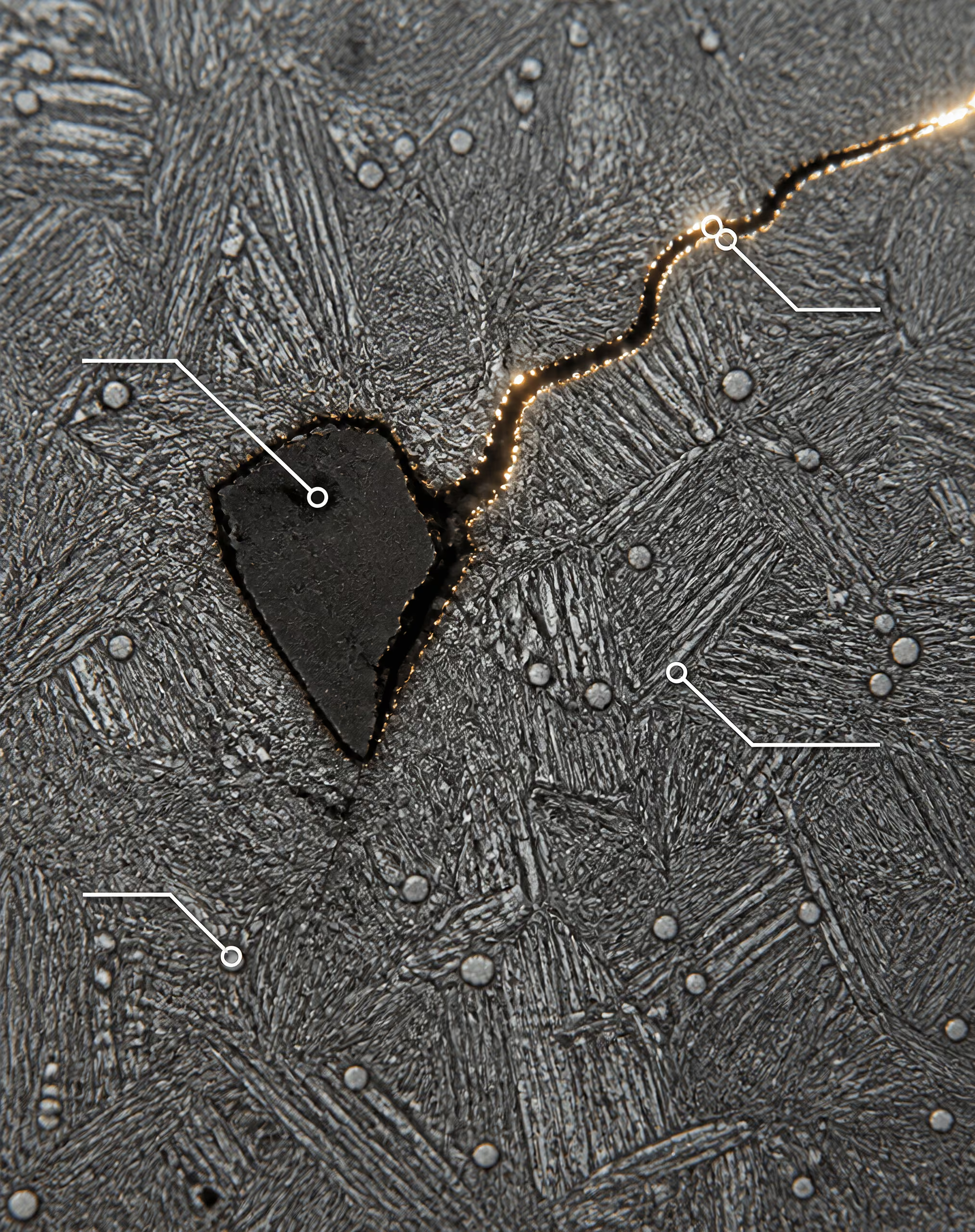
Nonmetallic inclusion A nonmetallic particle embedded in steel, such as an oxide, sulfide, silicate, aluminate, or complex inclusion, that may disturb the local stress field.
A rolling contact repeatedly compresses and shears a near-surface volume of steel. The nominal Hertzian stress is calculated from geometry, load and contact dimensions, but the steel does not experience that stress as a perfectly uniform continuum. An inclusion interrupts the metallic matrix. Its elastic modulus, shape, bonding to the surrounding steel and resistance to deformation differ from those of the martensitic, bainitic or case-hardened matrix around it.
That mismatch changes the local stress field. Tensile and shear stresses can concentrate at an inclusion boundary, especially at a sharp corner, an elongated end or a poorly bonded interface. Repeated passage of the contact then promotes a subsurface crack or a crack that reaches the raceway. Once a small crack forms, cyclic loading can extend it until a piece of the raceway or rolling element separates. The visible pit is late evidence; the metallurgical event began at a much smaller scale.
The principal material families described in the 2011 review Steels for bearings are through-hardened martensitic or bainitic steels and case-hardened steels having a hardened surface layer over a softer core. Both families can suffer inclusion-initiated rolling-contact fatigue. Case hardening changes the hardness and residual-stress profile with depth, while through-hardening produces a different matrix and core condition, but neither structure makes a harmful inclusion harmless.
Inclusions also interact with the operating system. SKF’s explanation of rolling-bearing fatigue links life to contact geometry, load distribution, lubrication and stress raisers. A raceway with an inclusion-derived depression can disturb the lubricant film, increase local pressure and generate further surface distress. Poor lubrication does not create the original inclusion, but it can reduce the time between initiation and visible damage. Water contamination provides another route to damage: experimental work reported through the U.S. Department of Energy’s Office of Scientific and Technical Information in 2024 found that dissolved or free water increased micropitting and rolling-contact-fatigue cracking and was associated with white-etching matter at crack interfaces.
Inclusion chemistry, size and morphology
“Cleanliness” is not a single chemical label. It describes the population of nonmetallic particles and the probability that a damaging particle lies in a highly stressed volume. Oxide inclusions commonly arise from deoxidation products, reoxidation or entrained slag. Sulfide inclusions form from sulfur-bearing reactions and may be relatively soft and deformable during rolling. Silicates, aluminates, spinels and complex calcium-bearing inclusions represent other possible populations, depending on steel chemistry, refractory interaction and ladle treatment.
Their effects differ. A hard, angular oxide or aluminate can behave as a severe stress raiser because it resists deformation and presents sharp geometrical features. A manganese sulfide inclusion may deform into a stringer during hot working, producing direction-dependent properties and an elongated interface. A complex inclusion may contain a hard core and a modified outer phase, so its fatigue behavior cannot be inferred from the nominal sulfur or oxygen content alone.
Size matters, but size by itself is not sufficient. A larger inclusion generally disturbs more matrix and presents a greater potential crack-initiation site. Location matters too: a particle positioned within the maximum orthogonal shear-stress region can be more damaging than a larger particle outside the principal stressed volume. Shape, aspect ratio, clustering, orientation, interfacial bonding and the surrounding carbide structure all alter the local result. Two heats with similar average oxygen values can consequently show different rolling-contact-fatigue performance if their largest inclusions, inclusion distributions or deformation histories differ.
The matrix remains important. NASA’s 1987 report on rolling-element fatigue identified hardness, retained austenite, grain size, and carbide size, number and area as factors influencing life. Excessive or poorly distributed carbides can affect crack paths and local stress; retained austenite can transform under service loading; grain size and matrix strength affect cyclic deformation. Cleanliness should therefore be read as a decisive variable within a microstructural system, not as a replacement for heat-treatment control.
Vacuum processing and steelmaking route
Steelmaking route determines how inclusions are generated, modified, removed or retained. Electroslag remelting, vacuum arc remelting and other secondary-melting practices can reduce particular inclusion populations and improve segregation control, but the result depends on the full process chain: melting, refining, casting, remelting, forging or rolling, heat treatment and inspection. A vacuum label is not a substitute for measured inclusion characterization.
NASA’s 1987 findings are especially important because they challenge chemistry-only explanations. The report found that processing such as double-vacuum melting could influence rolling-element fatigue life more strongly than chemistry alone. Double-vacuum routes commonly combine vacuum induction melting with vacuum arc remelting, reducing exposure to atmospheric reoxidation and improving control of dissolved gases and inclusion populations. The implication is direct: two steels with similar nominal alloy percentages can have different fatigue lives when their melting and refining histories produce different cleanliness levels or particle distributions.
ASTM STP 1327 places this issue alongside bearing life, rolling-contact fatigue, steelmaking, through-hardening, case-hardening, aerospace steels, corrosion-resistant steels and surface modification. That broader context matters because cleanliness is carried into the finished component. Forging can break up or elongate inclusions; machining can expose a subsurface particle; heat treatment can change the matrix surrounding it. Bearing life emerges from the resulting component under its actual contact stress, lubricant condition and contamination level. Chemistry sets possibilities. Clean steelmaking determines how many of those possibilities survive as fatigue-critical defects.
Microstructure After Heat Treatment
Heat treatment determines far more than the final hardness recorded on a test coupon. It establishes the phases that carry the rolling contact, the stresses left by quenching, the stability of the component during service, and the size and distribution of carbides that can either support wear resistance or initiate fatigue damage. A bearing raceway may therefore meet a nominal hardness specification yet perform poorly if its martensite is too brittle, its retained austenite transforms during operation, or its carbide population contains large, poorly distributed particles.
The principal material classes are through-hardened martensitic or bainitic steels, and case-hardened steels in which a hard surface layer is supported by a softer core, as described in the 2011 review Steels for bearings. High-carbon chromium bearing steel is a standard material for rolling elements and raceways according to NTN (2020). A familiar designation is SAE 52100, also written AISI 52100 in many engineering references; its performance depends on the complete melting, forging, rolling, heat-treatment and finishing route rather than on the designation alone.
Martensite, bainite and tempered structures
Quenched martensite provides high hardness because carbon is trapped in a supersaturated iron lattice. That hardness raises resistance to the repeated shear and compressive stresses generated below a raceway or rolling-element contact. It is not sufficient by itself. Untempered martensite has high internal stress and limited fracture tolerance, so it is normally tempered to reduce quench stress and adjust the balance between hardness and toughness.
Tempering precipitates carbon from martensite and changes its tetragonality, strength and fracture response. A properly tempered structure can resist plastic deformation under the contact while tolerating local stress concentrations better than untempered martensite. Excessive tempering, however, lowers hardness and can increase the depth of plastic deformation produced by each pass of the contact. Repeated deformation then accumulates around inclusions, carbide interfaces, grinding damage or other discontinuities.
Bainitic bearing steels follow a different transformation path. Depending on transformation temperature and processing, bainite can provide a useful combination of hardness, toughness and dimensional stability, with lower quench distortion than a fully martensitic route. Its fatigue response still depends on the fineness and uniformity of the bainitic structure, carbide condition and residual stress. “Bainitic” is not a single performance class: coarse or uneven transformation products do not carry contact stress in the same way as a fine, carefully controlled structure.
Case-hardened grades place a high-carbon, hard surface over a lower-carbon core. The case resists contact deformation, while the core can absorb some impact and bending stresses. Carbon potential, case depth, retained austenite, carbide precipitation and core transformation must be matched to the applied stress field. A case that is too shallow leaves high subsurface stress in softer material; a case that is too hard or poorly supported can become sensitive to cracking.
Residual stress adds another layer. Compressive residual stress near the working surface can delay crack opening, whereas tensile residual stress assists crack initiation and propagation. Quenching, carburizing, grinding and finishing can all alter this field. The useful residual-stress profile is therefore a process outcome, not a guaranteed consequence of high hardness.
Retained austenite and dimensional stability
Retained austenite Austenite that does not transform during quenching and remains as a metastable phase in the heat-treated steel.
Retained austenite is the austenite that remains after quenching instead of transforming to martensite. In a bearing steel, some retained austenite can improve toughness and accommodate local strain, but it is metastable. Contact pressure, cyclic shear, temperature and time may transform it into fresh martensite or other products during service.
That transformation can produce dimensional change and local stress. In precision bearings, even a small change in raceway geometry alters contact conformity, load distribution and lubrication-film thickness. The resulting change in peak stress may shorten fatigue life despite an initially acceptable hardness value. Transformation can also create fresh, relatively untempered martensite, which may become a crack-sensitive region unless subsequent tempering and service conditions control its response.
The opposite condition is also troublesome. If retained austenite is reduced too far or transformed too abruptly, the structure may lose some strain accommodation and become more brittle. Cryogenic treatment, stabilization tempering and tightly controlled quenching are used in some processing routes, but their effects depend on carbon content, alloying, section size and prior austenite condition. There is no universal retained-austenite percentage that defines a safe bearing.
NASA’s 1987 review of rolling-element fatigue identifies hardness and retained austenite among the variables affecting life, together with grain size and carbide size, number and area. That finding matters because retained austenite changes both the initial mechanical response and the structure encountered after millions of contact cycles. A hardness measurement made immediately after tempering does not describe the whole service history.
Lubrication and contamination can expose these weaknesses. The U.S. Department of Energy’s 2024 summary of experimental work reports that dissolved or free water increased micropitting and rolling-contact-fatigue cracking, with white-etching matter associated with crack interfaces. The lubricant controls the contact stress state at the surface, while the heat-treated structure controls how subsurface stresses are accommodated. Neither material nor lubricant can be assessed in isolation.
Grain size and carbide population
Prior-austenite grain size affects the scale of the transformation products formed during cooling. Fine prior-austenite grains generally provide shorter paths for crack propagation and can support a more uniform martensitic or bainitic structure. Coarse grains may concentrate transformation strain and create larger regions with similar crystallographic orientation, allowing fatigue cracks to develop or advance with less interruption. Grain refinement does not remove the need for cleanliness or correct tempering; it changes one part of the crack-initiation and crack-growth problem.
Carbides supply carbon and chromium-rich hard phases that contribute to wear resistance and maintain hardness. Their population must be judged by more than average size. NASA (1987) specifically reported effects from carbide size, carbide number and carbide area. Carbide area describes the fraction of the microstructure occupied by carbides; carbide number describes how many particles are present; size describes their scale and, critically, the upper tail of that distribution.
Fine, numerous and reasonably uniform carbides can support hardness without producing large isolated defects. Excessive carbide area can reduce the continuity of the load-bearing matrix. Large particles, carbide stringers left by working, or clusters aligned by rolling can act as local stress concentrators. The matrix and carbide have different elastic and plastic responses, so repeated contact can generate high interfacial stress. A crack may initiate at a carbide, at a carbide cluster, or at an inclusion adjacent to one.
Insufficient carbon or inadequate carbide formation creates the opposite problem: the steel may lack the hardness and wear resistance needed to withstand repeated contact without accumulating plastic strain. Increasing carbon or carbide content is not a simple remedy, because coarse undissolved carbides and segregation can increase crack-initiation risk. Heat treatment must dissolve enough carbon for the intended martensite or case, retain a controlled undissolved carbide population, and avoid excessive coarsening during austenitizing.
The ASM Handbook (2014) identifies steel cleanliness and freedom from harmful nonmetallic inclusions as the single most important factor, after suitable microstructure, in achieving high rolling-contact-fatigue life. Vacuum melting and related refining routes can therefore affect fatigue life more strongly than a small chemistry change. Processing history matters.
These material effects also need a statistical frame. ISO 281:2007 defines basic rating life as the life associated with 90% reliability; BS ISO 281:2007 is its British adoption. Schaeffler (2024) and JTEKT (2024) likewise define L10 as the number of revolutions reached or exceeded by 90% of apparently identical bearings before the first material-fatigue indications. That calculated life is not a promise made by hardness alone. It describes a population under stated assumptions, while the actual result reflects microstructure, inclusions, stress, lubrication, contamination, geometry and manufacturing variation.
Contact Mechanics, Load Distribution and Stress Raisers
Concentrated elastic contact
A rolling bearing does not carry load through a broad, uniformly stressed area. Each ball or roller presses against a raceway through a small contact patch, producing a concentrated elastic contact. The local pressure and subsurface shear stresses depend on the normal load, the radii of curvature, the elastic properties of the two bodies, and the shape of the contact. This is the Hertzian contact problem, but bearing contacts are not isolated textbook points: raceway curvature, conformity, crowning, contact angle, and the finite width of rollers alter the stress field.
The SKF handbook treats contact geometry and load distribution as central to bearing fatigue because the maximum orthogonal and shear stresses occur beneath the contact surface, not necessarily at the point of visible damage. A change in raceway curvature changes the size and pressure distribution of the contact ellipse. A roller with inadequate end relief can produce a high pressure concentration at its edge, where the local stress may greatly exceed the value predicted from the nominal bearing load. Raceway waviness and form error have a similar effect by making the load fluctuate as the element rolls.
Nominal hardness therefore cannot define performance by itself. NTN identifies high-carbon chromium bearing steel as a standard material for rolling elements and raceways, commonly represented by grades such as AISI 52100 and its national or company designations. Yet a component made from this steel can experience a different stress history when its conformity, contact angle, or raceway profile changes. The steel supplies a material capability; geometry determines how much of that capability the contact consumes on every revolution.
Surface condition also enters the contact calculation. Roughness asperities can penetrate the lubricant film when the film is thin, producing local metal-to-metal interaction and short-wavelength pressure peaks. Water contamination makes the situation worse. A 2024 U.S. Department of Energy study reported that dissolved or free water increased micropitting and rolling-contact-fatigue cracking and was associated with white-etching matter at crack interfaces. Lubrication is therefore part of contact mechanics, not merely a maintenance concern.
The rating calculation is a statistical engineering measure, not a promise that every bearing will fail at one fixed stress or revolution count. ISO 281:2007 specifies methods for dynamic load ratings and basic rating life for rolling bearings made from high-quality hardened bearing steel; its basic rating life is associated with 90% reliability. BS ISO 281:2007 is the British adoption. Schaeffler defines L10 as the number of revolutions reached or exceeded by 90% of apparently identical bearings before the first indications of material fatigue. Adjusted life can account for lubrication, contamination, reliability, and fatigue-limit load, but those factors still describe a particular operating system rather than hardness alone.
Load sharing among rolling elements
The applied radial or axial load is divided among the rolling elements, but the division is unequal. The element nearest the load line carries the greatest force, while elements farther around the bearing carry progressively less and may carry almost none under some conditions. The loaded-zone size and the force on each element depend on radial clearance, elastic deformation, contact angle, ring stiffness, fit, preload, external load, and internal geometry.
A bearing with excessive clearance can concentrate the external load into a small number of elements. The maximum element load then rises, increasing the Hertzian pressure and the subsurface stress cycle. Excessive preload creates the opposite-looking but related problem: more elements share the load, yet every element carries a permanent force before the external load is applied. If preload is too high, frictional heating, contact pressure, and fatigue damage can all increase. The same bearing steel can consequently produce very different lives under loose fit, tight interference fit, or excessive preload.
Misalignment changes the distribution again. An angularly misaligned inner and outer ring may force a ball or roller to contact one raceway near an edge. In cylindrical roller bearings, skew can shift load toward roller ends; in ball bearings, ring tilt can distort the contact ellipse and produce edge loading. Shaft bending, housing distortion, and inaccurate shoulders can create these conditions even when the nominal bearing load is within the catalog rating.[7] Bearing Knowledge: Basic Dynamic Load Rating and Rating Life. JTEKT. JTEKT Bearing Knowledge, 2024.
Fits affect more than retention. An excessive interference fit can reduce internal clearance, increase preload, and distort a thin bearing ring. A loose fit can permit ring creep or micro-slip, generating fretting and additional surface damage. JTEKT describes the basic dynamic load rating as a measure of rolling-fatigue capacity and states that L10 corresponds to 90% reliability for bearings manufactured from specified bearing steels or equivalent materials. That statement assumes the bearing is operating within the geometry, loading, and installation conditions represented by the rating method.
The stress history also depends on material state. The 2011 review Steels for Bearings separates through-hardened martensitic or bainitic steels from case-hardened steels, which have a hardened surface layer over a softer core. NASA reported in 1987 that hardness, retained austenite, grain size, and carbide size, number, and area influence rolling-element fatigue life. The ASM Handbook, 2014, identifies steel cleanliness and freedom from harmful nonmetallic inclusions as the single most important factor after suitable microstructure in achieving high rolling-contact-fatigue life. A clean, correctly processed AISI 52100 contact can therefore outlast a harder but dirtier one under the same nominal load.
Surface defects and geometric discontinuities
Rolling-contact fatigue has two broad origins. Subsurface-origin fatigue begins beneath the raceway, often at a stressed inclusion or a region of unfavorable microstructure, and may develop into a spall after repeated shear loading. Surface-origin damage begins at the raceway or rolling-element surface, where roughness, inadequate lubrication, sliding, contamination, or a defect concentrates stress. The distinction matters because a polished surface cannot remove a harmful internal inclusion, while excellent internal cleanliness cannot prevent a dent from acting as a repeated crack starter.
Nonmetallic inclusions are especially important because their elastic and interfacial behavior differs from that of the surrounding steel. The ASM finding places cleanliness immediately after suitable microstructure in importance. Processing can matter more than a small chemistry change: NASA’s 1987 work identified double-vacuum melting and related processing effects as influential in rolling-element fatigue life. Chemistry determines possible phases and hardenability, but melting, forging, heat treatment, and carbide control determine whether the finished raceway contains damaging local features.

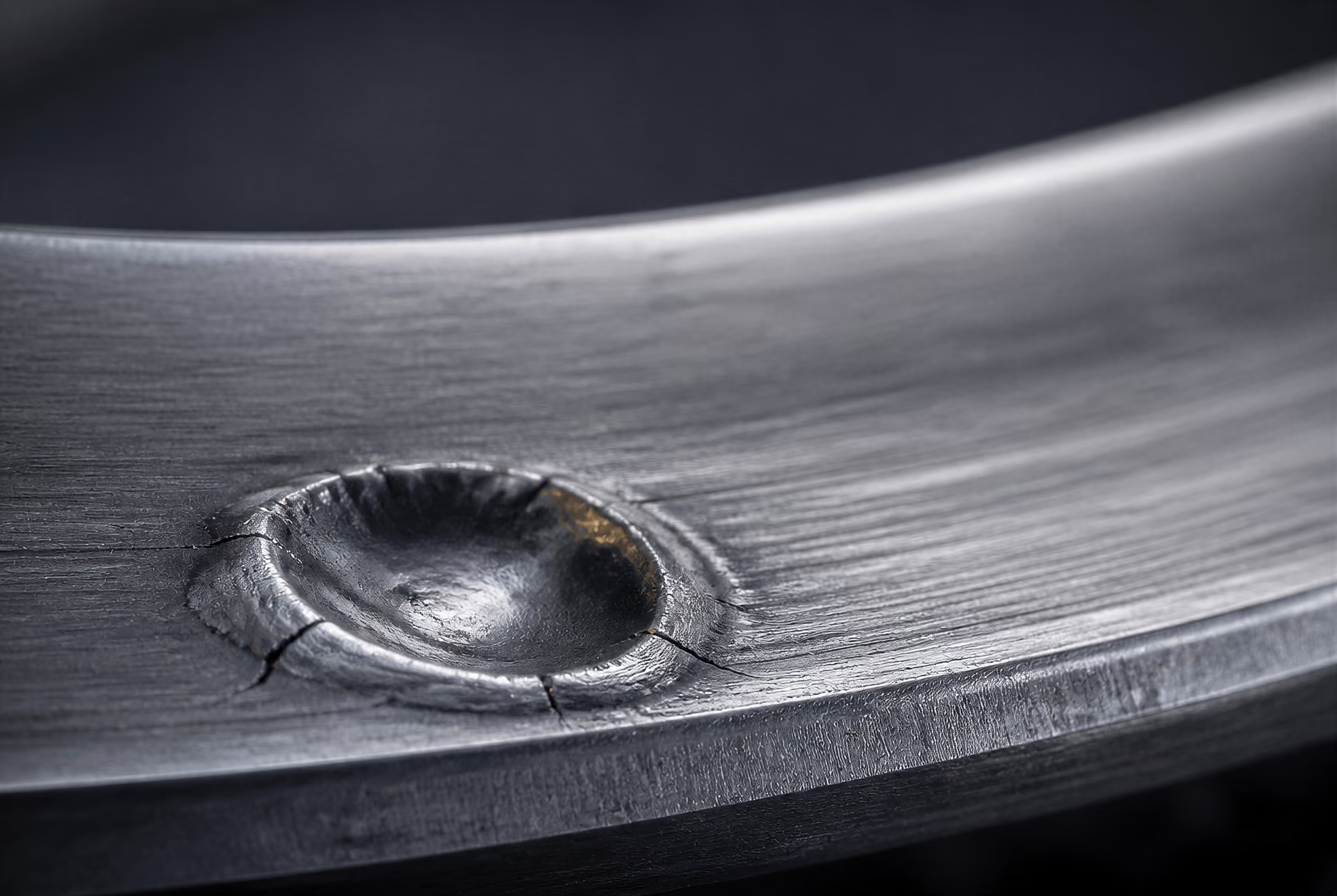
A dent from a hard contaminant is a geometric discontinuity, not simply a cosmetic mark. Each passing element strikes its rim, creating a pressure spike and a zone of plastic deformation. Handling damage at a shoulder, raceway, or roller end can produce the same effect. Scratches, grinding burns, waviness, and raised burrs interrupt the intended contact geometry. Under thin-film lubrication, these features can initiate micropitting or surface-origin cracks; under heavier load, they can accelerate a crack into a larger spall.
The practical result is direct: calculated bearing life belongs to the bearing, its steel, its geometry, its fits, its preload, its lubricant, and its contamination history as one operating system. Changing any of those can change the local stress field while leaving the nominal grade and hardness unchanged.
Lubrication, Water and Micropitting
Film separation and metal-to-metal interaction
Lubrication does more than reduce friction between a rolling element and a raceway. The lubricant film changes how the two surfaces transmit load. Under full elastohydrodynamic lubrication, pressure in the entrained film separates most opposing asperities, so the nominal Hertzian contact is carried mainly through the lubricant rather than through repeated peaks in the steel surface. When film thickness falls relative to surface roughness, asperity contacts carry a larger share of the load. Their local stresses can greatly exceed the calculated smooth-contact stress, even when the bearing’s applied load has not changed.
This distinction matters because bearing calculations usually begin with geometry, load and material assumptions. ISO 281:2007 specifies methods for calculating dynamic load ratings and basic rating life for rolling bearings manufactured from high-quality hardened bearing steel. Its basic rating life is associated with 90% reliability. Schaeffler describes L10 in the same statistical terms: the number of revolutions reached or exceeded by 90% of apparently identical bearings before the first indications of material fatigue appear. JTEKT likewise defines the basic dynamic load rating as a measure of rolling-fatigue capacity and L10 as the life at 90% reliability for bearings made from specified bearing steels or equivalent materials.
Those definitions do not make lubrication a minor correction. They separate a calculated reference life from the service outcome of a particular bearing in a particular machine. Adjusted life methods account for lubrication, contamination, reliability and fatigue-limit load because these factors alter the stresses that actually reach the surface and subsurface. A bearing made from high-carbon chromium bearing steel, the standard material identified by NTN for rolling elements and raceways, can still suffer early distress if its lubricant cannot maintain separation.
Film thickness depends on viscosity, speed, load, temperature, surface finish and contact geometry. A rise in temperature lowers viscosity; a slow oscillating motion may prevent adequate film formation; and a high load compresses the film while increasing subsurface stress. Misalignment and edge loading further concentrate pressure in a small region. Add abrasive particles, and the particles can indent the raceway, producing a permanent stress raiser that survives after the contaminant has passed. Water can reduce lubricant-film performance, promote corrosion, alter additive reactions and change the way surfaces interact. The contact may then shift repeatedly between partial separation and direct metal-to-metal impact.
Micropitting as a surface fatigue process
Micropitting is a form of surface fatigue, not simply a roughness defect or a cosmetic stain. It begins when repeated asperity contacts, sliding, local plastic strain and near-surface tensile stresses create very small cracks. The cracks may grow at shallow angles beneath the surface and open into grey or frosted regions composed of many minute pits. A surface can therefore look only lightly discoloured while its load-carrying geometry and crack population are already changing.
The critical variable is the combined condition of contact stress and film separation. A low lambda ratio—the ratio of lubricant-film thickness to composite surface roughness—means that more asperities interact. Sliding can add shear stress to the repeated compressive loading imposed by rolling. If an asperity, dent or inclusion raises the local stress sufficiently, a crack can initiate at or near the surface and then propagate under cyclic loading. Micropits may coalesce into larger flaking damage, although the transition is not automatic or immediate.
This is why nominal hardness cannot predict bearing life by itself. NASA reported in 1987 that hardness, retained austenite, grain size, and carbide size, number and area all influence rolling-element fatigue life. The steel’s processing history also matters: double-vacuum melting and related improvements in cleanliness can affect life more strongly than a modest change in alloy chemistry. The ASM Handbook, in its 2014 bearing-steels treatment, identifies steel cleanliness and freedom from harmful nonmetallic inclusions as the single most important factor after suitable microstructure in achieving high rolling-contact-fatigue life.
An inclusion and a lubricant-related surface defect can interact. An inclusion beneath a raceway produces an elastic-modulus mismatch and a local stress concentration. Poor film separation then adds severe surface loading above that subsurface site. Conversely, a micropit or contaminant dent can increase the stress field around an otherwise harmless region of steel. The resulting fatigue process belongs to the complete bearing system, not to a hardness number printed on a material certificate.
The principal material families described in the 2011 review Steels for bearings are through-hardened martensitic or bainitic steels and case-hardened steels with a hard surface layer over a softer core. Both can provide suitable rolling-contact performance, but neither class removes the need for controlled processing, appropriate heat treatment, adequate lubrication and clean operating conditions. A hard surface can resist indentation while still developing fatigue cracks if the contact repeatedly experiences severe asperity interaction.
Water contamination and white-etching matter
Water is an active contaminant in a rolling bearing, not merely a diluent that lowers lubricant viscosity. It may be present as dissolved water, free water, condensation or a dispersed emulsion. Its effects depend on concentration, temperature, lubricant chemistry, operating speed and the condition of the steel surface. Water can reduce film-forming ability, promote hydrogen-related reactions or corrosion, disturb additive films and help produce corrosive or mechanically damaged sites from which fatigue can begin.
Dissolved or free water in lubricant increased micropitting and rolling-contact-fatigue cracking and was associated with white-etching matter at crack interfaces. Preliminary evidence
Experimental work reported through the U.S. Department of Energy’s Office of Scientific and Technical Information in 2024 found that dissolved or free water in lubricants increased the occurrence of micropitting and rolling-contact-fatigue cracks. The same work associated water contamination with white-etching matter at crack interfaces. This finding links a lubricant condition with both surface distress and the microstructural features observed around fatigue cracks. It does not mean that every water-exposed bearing will fail through one identical path, nor that white-etching matter has one universal cause.
White-etching matter is a microstructural region that etches more lightly than the surrounding bearing steel, often appearing around cracks or beneath damaged surfaces. Reports have associated such matter with altered ferrite, carbide dissolution or redistribution, severe plastic deformation, crack-tip effects and hydrogen-related mechanisms, depending on the bearing, lubricant and operating history. Water may contribute to some of these processes by changing tribochemical conditions and crack-tip reactions. Other cases may be driven by high stress, electrical discharge, sliding, material defects or long-term deformation. Treating white-etching matter as proof of one specific failure mechanism overstates what microscopy alone can establish.
Lubricant contamination must also be kept separate from steel cleanliness. Water, particles and degraded additives enter the bearing during manufacture, assembly, storage or operation; nonmetallic inclusions are features of the steelmaking and processing route. The ASM conclusion about cleanliness concerns the latter. A clean steel can be damaged by contaminated lubricant, while a highly filtered lubricant cannot remove an inclusion already embedded beneath the raceway. In service, however, the mechanisms can reinforce one another: an inclusion supplies a subsurface stress raiser, a water-weakened film increases asperity loading, and the resulting crack may develop white-etching matter at its interface.
Life improvement therefore requires control of both sides of the contact. Material selection and melting practice reduce internal initiation sites; heat treatment controls martensite, bainite, retained austenite and carbides; filtration and sealing limit particles and water; and lubricant selection preserves film separation at the actual temperature and speed. The resulting life is a statistical system outcome, not a simple consequence of alloy designation or nominal hardness.
From Crack Initiation to Rolling-Contact Failure
Rolling-contact fatigue begins beneath, at, or near the loaded surface when repeated Hertzian contact stresses exceed the local resistance of the steel. A bearing raceway may appear smooth and undamaged while each passing rolling element produces a brief, intense stress pulse. The maximum orthogonal shear stress usually lies below the surface, but its position and magnitude change with contact geometry, load distribution, lubrication, surface topography and traction. A defect, carbide cluster, residual-stress field or mechanically damaged region can concentrate that cyclic stress enough to nucleate a crack.
The subsequent failure is not determined by nominal hardness alone. High-carbon chromium bearing steel, including 100Cr6 and AISI 52100 designations used for through-hardened bearing components, can have very different fatigue performance depending on cleanliness, heat treatment, retained austenite, carbide morphology and processing history. NTN identifies high-carbon chromium bearing steel as a standard material for rolling elements and raceways. The review Steels for bearings (2011) separates bearing steels into through-hardened martensitic or bainitic grades and case-hardened steels, in which a hard surface layer is supported by a softer core. Both families can fail by rolling-contact fatigue, but their stress profiles and crack paths differ.
Subsurface crack initiation
A nonmetallic inclusion is often the most important local stress raiser in a clean-looking bearing steel. Oxides, sulfides, silicates and complex inclusion clusters differ from the surrounding tempered martensitic matrix in elastic modulus, shape, bonding and deformability. Under repeated rolling contact, the inclusion–matrix interface can debond, or a crack can form in the matrix beside a sharp inclusion edge. The crack then grows within the region of cyclic subsurface shear stress.
The ASM Handbook’s 2014 discussion of bearing steels identifies steel cleanliness and freedom from harmful nonmetallic inclusions as the single most important factor, after suitable microstructure, in achieving high rolling-contact-fatigue life. This does not mean that every inclusion causes failure. Size, morphology, location, orientation, distance from the maximum stress zone and local stress history all matter. A small, rounded inclusion may be harmless where a larger angular oxide lies directly beneath the contact track.
Microstructure controls how the steel responds around that defect. NASA’s 1987 bearing-fatigue work reports that hardness, retained austenite, grain size, and carbide size, number and area influence rolling-element fatigue life. Excessive carbide segregation can provide crack paths; an unsuitable retained-austenite content can alter dimensional stability and transformation behavior; and coarse grains or poor tempering can reduce resistance to cyclic damage. Processing can outweigh a simple chemistry comparison. Double-vacuum melting, for example, may improve fatigue performance by reducing harmful inclusions even when the nominal alloy analysis changes little.
The first crack is therefore a local event inside a loaded material system. It may remain dormant for many cycles, extend a short distance parallel to the raceway, or turn toward the surface as the surrounding stress field changes. A hardness value measured on an accessible cross-section cannot reveal which of these conditions exists.
Crack propagation and spalling
Once a subsurface crack reaches a critical size, repeated rolling and sliding drive it through the stressed material. Crack faces may rub, oxidize or accumulate wear debris. Branches can develop where the crack encounters carbides, prior-austenite grain boundaries, inclusions or regions with different residual stress. Eventually, a branch connects with the raceway surface, or a near-surface crack isolates a fragment of steel.
Spalling is the resulting material-removal event: a piece of the hardened raceway or rolling element separates, leaving a crater with a fractured floor and raised or displaced edges. The detached fragment is not merely a stain or polished mark. It is a fatigue-generated piece of bearing steel, and the crater increases impact, vibration and local stress as subsequent rolling elements cross it. Detached particles can also circulate through the lubricant, producing secondary indentations and additional stress raisers.
This progression explains why the visible damage may be much larger than the initiating defect. A microscopic inclusion can start a crack, while the final spall removes a millimetre-scale area after crack branching and repeated surface loading. The load may remain below the static yield strength of the bulk component, yet local cyclic stresses at the defect and crack tip can still produce fatigue.
Bearing-life terminology must be kept separate from this metallurgical sequence. ISO 281:2007 specifies methods for dynamic load ratings and basic rating life for rolling bearings manufactured from high-quality hardened bearing steel; its basic rating life corresponds to 90% reliability. BS ISO 281:2007 is the British adoption. Schaeffler defines L10 as the number of revolutions reached or exceeded by 90% of apparently identical bearings before the first indications of material fatigue, and JTEKT gives the same 90% basis for bearings made from specified bearing steels or equivalent materials. L10 is a statistical reference, not a promise that every bearing will spall at that point. Adjusted life can incorporate lubrication, contamination, reliability and fatigue-limit load. It describes an operating system, not chemistry in isolation.
Surface-origin fatigue and micropitting
Surface-origin damage begins where the contact is exposed to lubrication and handling conditions. If the lubricant film is too thin for the combined surface roughness, opposing asperities touch repeatedly. Low viscosity, insufficient lubricant supply, excessive temperature, sliding, water contamination and incorrect lubricant chemistry can all reduce film protection. A dent from a hard particle or assembly impact produces a sharper stress concentration than its shallow depth suggests. Debris passing through the contact can indent one raceway and raise a lip around the indentation, initiating cracks at the edge.
Micropitting is an early form of surface fatigue characterized by many small, shallow cavities and a gray or frosted appearance. It is associated with asperity interaction, local plastic deformation, surface-origin cracks and loss of the near-surface material. Micropits are not the same as a mature spall. A spall is a larger fatigue crater formed after crack growth has detached a coherent fragment; micropitting generally consists of fine, distributed surface removals before that scale of detachment occurs. If lubrication and loading remain unfavorable, micropitting can coalesce, deepen and develop into more severe surface-origin fatigue.
Water can worsen both mechanisms. A 2024 U.S. Department of Energy study reported that dissolved or free water in lubricant increased micropitting and rolling-contact-fatigue cracking and was associated with white-etching matter at crack interfaces. White-etching matter is a metallurgical feature, not a diagnosis by itself: its presence must be interpreted with crack geometry, local deformation, thermal history and operating conditions.
Post-failure examination therefore has to join several observations. The fracture location indicates whether the initiating process was subsurface or surface-connected; metallography reveals martensite, bainite, retained austenite, carbides, decarburization and white-etching regions; inclusion analysis establishes whether a nonmetallic particle lies at the origin; and lubricant, seal, contamination and load records test the operating explanation. Contact stress, misalignment, duty cycle and traction may explain why a defect became active. A bearing cannot be assigned a material cause from a spall photograph or a hardness reading alone.
Processing Routes and Quality Control
ASTM STP 1327 organizes bearing-steel production around four linked stages: steelmaking, through-hardening, case hardening and surface modification. That sequence is more useful than treating a grade designation as a complete description of fatigue capability. A bearing may be made from a recognized high-carbon chromium steel and still show poor rolling-contact-fatigue life if its inclusion population, carbide structure, heat-treatment response or finished geometry is uncontrolled. NASA’s 1987 review reaches the same practical conclusion: hardness, retained austenite, grain size, and carbide size, number and area all influence rolling-element fatigue life, while processing differences such as double-vacuum melting can matter more than modest changes in chemical composition.
Primary and secondary steelmaking
Processing and quality-control sequence
- Melting and refining Control composition, gases, slag interactions, and inclusion formation.
- Casting and remelting Limit segregation and internal discontinuities through controlled solidification or remelting.
- Forging or rolling Refine the cast structure and control deformation, banding, and grain size.
- Heat treatment Establish martensite, bainite, carbides, retained austenite, and residual stress.
- Inspection Verify cleanliness, hardness, microstructure, geometry, surface condition, and case depth.
The route begins with charge selection, melting and refining. High-carbon chromium bearing steel is a standard material for rolling elements and raceways, as NTN describes, while other applications use alloyed through-hardening steels, bainitic grades, or case-hardening steels. The familiar designation AISI 52100, commonly written as ASTM A295 Grade 52100 for bearing-quality bar and wire, is not a guarantee of identical internal quality from one heat or producer to another. Chemical limits define a composition window; they do not define the number, size, morphology or distribution of nonmetallic inclusions.
Primary steelmaking establishes the bulk composition and removes part of the dissolved oxygen, sulfur and other unwanted elements. Secondary metallurgy then controls the details that become critical in rolling contact: deoxidation practice, vacuum treatment, slag-metal reactions, temperature, stirring, inclusion modification and casting conditions. Calcium treatment, for example, may alter inclusion shape, but an inclusion that is less angular is not automatically harmless in a highly stressed raceway. Its chemistry, size, position relative to the contact, and bonding with the surrounding matrix still matter.
Clean steel requires control across the entire route. Reoxidation during transfer, entrained slag, mold powder contamination, poor tundish practice and centerline segregation can introduce defects that a final hardness test will miss. Electroslag remelting, vacuum arc remelting and other refining routes can reduce particular defect populations, but each has process limits and must be judged by the resulting material rather than by the process name alone. Forging or rolling subsequently breaks up cast structure and redistributes segregation; reduction ratio, deformation temperature and cooling history affect carbide banding, grain size and ultrasonic detectability.
A certificate listing carbon, chromium, manganese, silicon, phosphorus and sulfur therefore establishes chemical conformity only. It does not, by itself, establish rolling-contact-fatigue performance. The ASM Handbook’s 2014 bearing-steel treatment identifies cleanliness and freedom from harmful nonmetallic inclusions as the single most important factor after suitable microstructure in obtaining high rolling-contact-fatigue life. That hierarchy is a warning against ranking steels by nominal carbon or chromium content alone.
Vacuum melting and remelting concepts
Vacuum processing addresses gases and inclusions, but “vacuum melted” is not a single quality level. Vacuum induction melting (VIM) melts and refines the charge under reduced pressure, helping remove dissolved hydrogen and limiting atmospheric contamination while permitting close composition control. Vacuum arc remelting (VAR) then remelts a consumable electrode under vacuum. The controlled solidification can reduce segregation and voids and can produce a cleaner, more uniform ingot. A VIM-VAR route is often called double-vacuum melting.
The purpose is not simply to raise hardness. Lower hydrogen reduces the risk of flaking and internal cracking; improved solidification control reduces harmful segregation; and a lower inclusion burden reduces local stress concentration under repeated Hertzian contact. NASA’s 1987 findings are important here because they place processing history beside, and sometimes ahead of, chemistry as a life determinant. Two heats within the same nominal specification can respond differently to spheroidizing, austenitizing, quenching and tempering because their prior segregation and carbide populations differ.
Remelting also has trade-offs. Electrode quality, arc stability, melt rate and ingot geometry influence segregation and defects. A remelted heat still needs forging, heat treatment and inspection. Vacuum treatment cannot repair an unfavorable finished microstructure or remove a raceway grinding burn. Nor does it eliminate the need to control lubrication and contamination in service. Experimental work reported through the U.S. Department of Energy in 2024 found that dissolved or free water in lubricant increased micropitting and rolling-contact-fatigue cracking and was associated with white-etching matter at crack interfaces. Material processing and operating conditions meet at the contact.
After steelmaking, ASTM STP 1327’s distinction between through-hardening, case hardening and surface modification helps define what must be checked. Through-hardened martensitic or bainitic steels have a hardened section through the working component. Case-hardened steels provide a hard carbon-enriched surface over a softer, tougher core, which can improve resistance to indentation and support subsurface stress. Surface modification may include controlled grinding, superfinishing, nitriding or other treatments that alter roughness, residual stress or near-surface hardness. These routes change the stress field; they do not make inclusions irrelevant.
Inspection of cleanliness and microstructure
Metallography links the production route to the structure that actually carries the load. A polished and etched section can reveal prior-austenite grain size, martensite or bainite, carbide networks, banding, decarburization, quench cracks and abnormal constituents. Optical microscopy is commonly supplemented by scanning electron microscopy and energy-dispersive analysis when an inclusion or crack origin requires identification. The question is not merely whether the steel is hard, but whether its matrix and second phases provide a stable, crack-resistant structure.
Inclusion rating measures the amount, type, size and distribution of nonmetallic matter against a specified comparison method, such as ASTM E45. Oxide, sulfide, silicate and globular inclusion ratings can expose differences that bulk chemistry conceals. Automated inclusion analysis may add size-distribution data and inclusion maps, while ultrasonic inspection can detect larger internal discontinuities over a production volume. A rating is a sampling result, not a direct life prediction: a rare inclusion near the maximum subsurface shear-stress region can dominate one bearing’s failure even when the average rating appears acceptable.
Carbide assessment is equally necessary in high-carbon chromium steels. Excessive carbide networks, coarse undissolved carbides, carbide banding or poor spheroidization can promote cracking, impair toughness and produce uneven response during austenitizing. Measurements should address carbide size, number, area fraction and distribution. NASA specifically identifies all four features—along with hardness, retained austenite and grain size—as variables affecting rolling-element fatigue life.
Hardness measurement verifies the response of the heat treatment, using a specified scale and locations rather than one convenient surface reading. Retained austenite requires a separate measurement, commonly by X-ray diffraction, because two parts with the same Rockwell hardness can contain different amounts that transform or dimensionally change during service. Dimensional inspection then checks raceway geometry, roundness, waviness, runout, case depth, grinding damage and surface roughness. Contact geometry and load distribution determine the calculated stresses, so a chemically conforming steel with poor geometry is not a conforming fatigue system.
ISO 281:2007 calculates dynamic load ratings and basic rating life for rolling bearings made from high-quality hardened bearing steel; its basic rating life is the life associated with 90% reliability. Schaeffler and JTEKT therefore define L10 statistically, as the revolutions reached or exceeded by 90% of apparently identical bearings before the first indications of material fatigue. Adjusted life additionally considers lubrication, contamination, reliability and fatigue-limit load. Quality control establishes material capability. It does not turn a chemical certificate into an L10 guarantee.
Through-Hardened Versus Case-Hardened Bearing Steels
Bearing steels are often divided into two material architectures: through-hardened steels, whose useful section is hard from the contact surface toward the interior, and case-hardened steels, whose hard outer layer is supported by a tougher, lower-carbon core. The distinction is not simply a choice between “hard” and “soft.” It determines how contact stresses, subsurface shear stresses, impact loads, crack growth and manufacturing distortion are managed.
Neither architecture guarantees a particular bearing life. ISO 281:2007 defines methods for calculating dynamic load ratings and basic rating life for rolling bearings made from high-quality hardened bearing steel; its basic rating life is the life associated with 90% reliability. Schaeffler and JTEKT likewise define L10 as the number of revolutions reached or exceeded by 90% of apparently identical bearings before the first material-fatigue indications appear. That statistical result describes a bearing population, not a hardness number.
Uniform hardness through the section
Through-hardened bearing steels are commonly high-carbon chromium grades such as AISI/SAE 52100, also designated 100Cr6 in EN ISO 683-17 and SUJ2 in JIS G 4805. NTN identifies high-carbon chromium bearing steel as a standard material for rolling elements and raceways. After austenitizing, quenching and tempering, the steel develops a predominantly martensitic structure containing finely distributed carbides. Bainitic through-hardening is another route used for selected bearing designs and heat treatments, with the transformation schedule chosen to obtain the required strength, dimensional stability and fatigue performance.
The main advantage is continuity. The raceway or rolling element does not pass abruptly from a hard case into a markedly softer interior. Subsurface stresses therefore encounter a material with broadly similar strength through the loaded zone, which suits many conventional rolling contacts. This is particularly useful when the maximum orthogonal and shear stresses lie below the surface, as they do in Hertzian contacts. The entire section can carry compressive and shear loading, while the matrix resists plastic deformation around carbides and other local stress raisers.
“Uniform hardness” does not mean uniform microstructure. A 52100 bearing ring may contain variations in martensite, retained austenite, carbide size, carbide distribution and prior-austenite grain size through its section. Heat-treatment response also depends on section thickness and cooling conditions. NASA reported in 1987 that hardness, retained austenite, grain size, and carbide size, number and area all influence rolling-element fatigue life. Excessive retained austenite may transform under service and contribute to dimensional change; excessive carbide size or segregation can create local crack-initiation sites even when the measured hardness is within specification.
Cleanliness is just as decisive. The ASM Handbook, 2014, identifies steel cleanliness and freedom from harmful nonmetallic inclusions as the single most important factor after suitable microstructure in achieving high rolling-contact-fatigue life. An inclusion near the maximum shear-stress zone can produce a local tensile field, initiate a crack and dominate the failure distribution. Vacuum melting, electroslag remelting, inclusion control and careful forging may therefore change fatigue performance more than a modest alteration in nominal alloy chemistry. NASA test work also found that processing, including double-vacuum melting, could affect life strongly.
Through-hardening has limits. A large ring or heavily loaded component may develop hardness gradients, residual stresses and distortion during quenching. The required section strength can also reduce tolerance to impact or edge damage, especially where the geometry creates stress concentration. A hardness traverse, retained-austenite measurement, metallographic examination and dimensional inspection are more informative than a single surface-hardness reading.
Hardened surface over a tougher core
Case-hardened bearing steels place the highest hardness where rolling contact occurs and retain a tougher, less highly carbonated core beneath it. Common carburizing grades include 16MnCr5 under EN ISO 683-3, SAE 5120 and SAE 8620; bearing-specific selection still depends on the applicable product, drawing and quality requirements. Carburizing or carbonitriding enriches the surface, followed by hardening and tempering to produce a martensitic case. The core may remain lower in carbon and therefore more tolerant of impact, bending and crack-driving loads than a fully hardened section.
The case must be deep enough to contain the important contact-stress field under the specified load, geometry and duty. There is no defensible universal case-depth value. A shallow case can allow the high-shear region to reach the case/core transition, where hardness, residual stress and microstructure change. A deeper case increases processing time and can increase distortion, retained austenite or quench-related cracking if the treatment is poorly controlled. Case depth should therefore be defined by hardness profiles, effective case-depth criteria, calculated stress distribution and validation under representative loading—not by a generic number copied from another bearing.
The transition region matters as much as the nominal surface and core values. It should not contain a sharp weakness caused by excessive carbide precipitation, carbon gradients, soft transformation products or unfavorable residual stress. A properly designed profile can place compressive residual stress near the surface, support resistance to crack opening and retain a core capable of absorbing impact energy. But the core is not a substitute for correct contact design. If a crack begins at a nonmetallic inclusion, a grinding burn, a surface dent or a lubricant-contamination scar, core toughness may not prevent rolling-contact fatigue.
Carburizing also introduces a dimensional problem. The carbon-enriched layer, quench transformation and subsequent tempering can produce changes in diameter, roundness and raceway profile. Distortion is especially important in thin rings, large rings, crowned contacts and components requiring tight preload or clearance control. Machining allowances, fixture design, quench control and final grinding must be planned together. The case architecture has mechanical value only if the finished bearing preserves the intended geometry.
Selection logic for impact and fatigue loading
The choice follows the load path, not a general ranking of steel types. A through-hardened martensitic or bainitic steel is often appropriate when contact geometry is well controlled, impact is limited, section dimensions permit reliable heat treatment and the principal requirement is resistance to repeated Hertzian stress. It can provide a consistent load-bearing structure and a simpler material concept. That does not make it immune to inclusions, lubrication failure or contamination.
Case hardening becomes attractive when a bearing ring or rolling element must combine a highly resistant contact layer with greater tolerance of impact, shock, bending or fracture propagation in the interior. Automotive transmission bearings, large bearings and applications with transient overloads may benefit from this separation of functions, provided the case depth, transition and core properties match the actual stress field. A tough core cannot compensate for an under-designed raceway, and a hard case cannot guarantee fatigue life if its cleanliness or microstructure is poor.
Geometry decides where the stress is concentrated. Raceway curvature, conformity, edge loading, flange contact, roller skew, preload and load distribution can make a case/core boundary either safely remote from the critical zone or a serious weakness. Lubrication and contamination then modify the damage process: a 2024 U.S. Department of Energy study reported that dissolved or free water increased micropitting and rolling-contact-fatigue cracking and was associated with white-etching matter at crack interfaces.
Material capability must therefore be separated from calculated life. ISO 281:2007, BS ISO 281:2007, Schaeffler and JTEKT provide the rating-life framework; adjusted life additionally accounts for lubrication, contamination, reliability and fatigue-limit load. The right architecture is the one whose stress profile, cleanliness, microstructure, distortion control and fracture tolerance fit the bearing’s geometry and duty. Nominal hardness alone cannot make that decision.
Aerospace, Corrosion-Resistant and Surface-Modified Bearing Steels
ASTM STP 1327 places aerospace steels, corrosion-resistant steels and surface modification beside the central subjects of bearing cleanliness, steelmaking, through-hardening, case-hardening, bearing life and rolling-contact fatigue. That grouping is useful because these materials are not simply stronger versions of conventional bearing steel. Each addresses a service constraint that can alter the failure mechanism, the manufacturing route or the life calculation.
Aerospace bearing-steel considerations
Aerospace bearings may face high speed, low lubricant supply, large temperature changes, vibration, vacuum or restricted maintenance access. The material therefore has to retain adequate hardness and dimensional stability while resisting rolling-contact fatigue under a tightly controlled contact geometry. Those requirements can conflict. Higher-temperature capability may require an alloy and tempering condition that reduce the hardness normally associated with room-temperature bearing steels; low-density or corrosion-resistant designs may impose different compromises in elastic modulus, carbide population or heat treatment.
Conventional high-carbon chromium bearing steel remains a reference material. NTN identifies high-carbon chromium bearing steel as a standard material for rolling elements and raceways, while through-hardened martensitic or bainitic steels form one of the principal bearing-steel families identified in the 2011 review Steels for bearings. Case-hardened steels form the other major family: a hard surface layer carries the contact, while a tougher, softer core supports it. The choice is not made from nominal hardness alone.
For aerospace grades, the relevant question is how the complete microstructure behaves through the stressed depth. NASA reported in 1987 that bearing-steel hardness, retained austenite, grain size, and carbide size, number and area all influence rolling-element fatigue life. Retained austenite can transform under service stress, changing dimensions and residual stress. Carbides that are coarse, poorly distributed or attached to harmful inclusions can act as stress raisers. Fine grains and suitable carbide control help, but neither guarantees immunity from fatigue.
Steelmaking can matter more than a small change in nominal alloy chemistry. Vacuum processing, including double-vacuum melting in applications where it is specified, reduces the population of damaging nonmetallic inclusions and can improve fatigue performance. The ASM Handbook stated in 2014 that steel cleanliness and freedom from harmful nonmetallic inclusions are the single most important factor, after suitable microstructure, in obtaining high rolling-contact-fatigue life. That finding is especially important in aerospace applications, where a small inclusion can control the life of an otherwise carefully heat-treated part.
Calculated life still has a defined statistical meaning. ISO 281:2007 gives methods for dynamic load ratings and basic rating life for rolling bearings made from high-quality hardened bearing steel; its basic rating life corresponds to 90% reliability. BS ISO 281:2007 is the British adoption. Schaeffler defines L10 in 2024 as the number of revolutions reached or exceeded by 90% of apparently identical bearings before the first indications of material fatigue. JTEKT gives the same 90% basis for bearings made from specified bearing steels or equivalent materials. Aerospace material capability does not turn L10 into a guaranteed service interval. Adjusted life must account for lubrication, contamination, reliability and fatigue-limit load, as well as load, speed and contact stress.
Corrosion-resistant bearing steels
Corrosion-resistant bearing steel addresses water, condensation, process fluids and aggressive atmospheres, but corrosion resistance usually consumes some of the compositional space used for high hardness and fatigue resistance. A chromium-rich stainless bearing grade such as AISI 440C, designated X105CrMo17 in EN 10088-3, can be hardened to a bearing-suitable structure, yet its performance depends on melting quality, carbide control, heat treatment, surface finish and the actual corrosive environment. “Stainless” describes resistance to a specified environment, not freedom from corrosion under all bearing conditions.
The same system variables remain active. Chlorides can produce localized corrosion pits, and a pit is a severe surface stress raiser in a rolling contact. Water in the lubricant creates another route to damage. A 2024 study indexed by the U.S. Department of Energy’s Office of Scientific and Technical Information found that dissolved or free water increased micropitting and rolling-contact-fatigue cracking and was associated with white-etching matter at crack interfaces. A corrosion-resistant alloy cannot compensate for contaminated lubricant, inadequate sealing, poor surface finish or excessive contact stress.
Vacuum and elevated-temperature service create related trade-offs. In vacuum, lubricant selection and outgassing may govern the system more strongly than the steel label. At elevated temperature, temper stability, dimensional change, retained-austenite transformation and lubricant degradation become central concerns. A grade that has sufficient room-temperature hardness may lose useful fatigue resistance after prolonged exposure if its microstructure changes. Conversely, an alloy selected for temperature stability may require different contact loads or a different life model. Material selection must therefore state the temperature range, atmosphere, lubricant, contact pressure and dimensional tolerance rather than simply naming a stainless or aerospace steel.
Surface modification and altered failure modes
Surface modification changes the near-surface condition: hardness, residual stress, friction, roughness, wear resistance or corrosion response. Case carburizing changes the hardness profile and places a tough core beneath the hardened case. Nitriding introduces a nitrogen-enriched hardened layer. Other treatments may alter the surface chemistry or produce a deposited layer, but their effect must be described by measured thickness, adhesion, roughness, residual stress and compatibility with the lubricant.
These treatments can move the critical failure site. A harder surface may reduce plastic deformation and some wear, yet a brittle compound layer, grinding burn, poor interface or tensile residual stress can initiate cracking. A modified surface can also change traction and slip, shifting heat generation or micropitting behavior. If a layer wears through, the exposed substrate may have a different hardness and corrosion response from the treated surface.
Surface treatment is consequently not an automatic substitute for clean steel or correct heat treatment. An inclusion below the treated zone remains an inclusion; a distorted raceway still produces the wrong contact geometry; and water-contaminated lubricant can still promote micropitting and rolling-contact fatigue. ISO 281:2007 basic rating life should not be interpreted as a universal credit for a coating or treatment. The credible claim is narrower: a specified surface process may improve a particular damage mechanism under validated loads, lubrication, temperature and contamination conditions, while introducing or exposing another failure mode.
How to Diagnose a Bearing-Fatigue Failure
A bearing failure investigation should begin before the bearing is cleaned, rotated, or cut apart. Preserve the assembly as found, photograph its position, and mark the load direction, rotational direction, and locations of the inner ring, outer ring, rolling elements, cage, seals, and lubricant. A displaced bearing can lose the evidence that separates a service event from a material-origin crack.

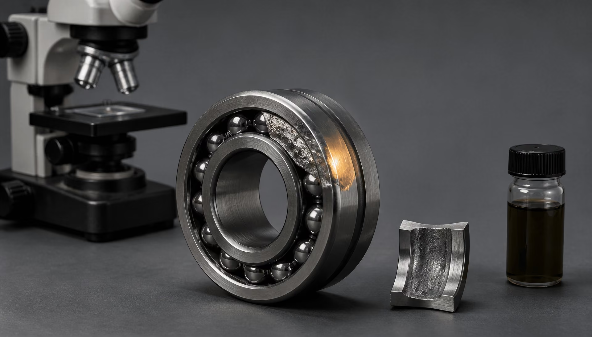
| Investigation area | Evidence to collect | What it can help distinguish |
|---|---|---|
| Damage map | Spalls, micropits, dents, smearing, cracks, and loaded-zone position | Surface-origin damage, subsurface fatigue, contamination, or misalignment |
| Lubricant and contamination | Water, particle count, viscosity, oxidation, wear metals, seals | Lubrication failure, debris damage, or water-associated distress |
| Geometry and installation | Clearance, preload, fits, runout, shoulders, alignment | Edge loading, load concentration, mounting damage, or distortion |
| Metallography | Matrix, inclusions, carbides, retained austenite, case depth | Material-origin crack initiation or heat-treatment abnormalities |
The first question is not “Was the steel hard enough?” It is “Where did damage start, how did it spread, and what stresses acted there?” Rolling-contact fatigue is a system result. Contact geometry, load distribution, lubrication, contamination, alignment, surface finish, heat treatment, inclusions, and manufacturing history can produce similar marks.
ISO 281:2007 and its British adoption, BS ISO 281:2007, define calculated dynamic load ratings and basic rating life for rolling bearings made from high-quality hardened bearing steel. The basic rating life is associated with 90% reliability, or L10. Schaeffler’s 2024 description similarly defines L10 as the number of revolutions reached or exceeded by 90% of apparently identical bearings before the first indications of material fatigue. That statistical definition is not a prediction that every bearing will fail at the same calculated mileage, nor does it identify the cause of an individual failure.
Visual and dimensional evidence
Record the damage pattern at low magnification before removing deposits. Map spalls, micropits, smearing, scuffing, discoloration, indentations, cracks, flaking, cage damage, and false-brinelling marks onto a drawing or coordinate system. Note whether damage is centered in the loaded zone, concentrated at one shoulder, repeated at roller spacing, confined to one axial edge, or distributed around the full raceway. The pattern often says more than the largest pit.
Measure raceway diameter, roundness, waviness, shoulder geometry, roller diameter variation, flange dimensions, radial and axial internal clearance, and preload where applicable. Compare measurements with the drawing and the bearing manufacturer’s tolerances. Check shaft and housing fits, seating shoulders, runout, squareness, and evidence of fretting. A raceway worn or damaged on one edge may indicate misalignment or mounting distortion rather than inadequate steel strength.
Inspect the surface with oblique lighting and calibrated magnification. Sharp, roughly circular dents with raised lips suggest hard debris passing through the contact. A dent can become a local stress raiser and later generate a fatigue spall, making debris damage resemble an inclusion-initiated failure. Repeated dents at regular rolling-element intervals support contamination, but a single large dent may result from assembly damage or a stationary impact.
Collect lubricant from the bearing, housing, filter, drain, and magnetic plug. Record viscosity grade, additive package, change interval, quantity, operating temperature, and replenishment practice. Test for particle count, water, oxidation, viscosity change, and wear metals when samples remain. Record speed, load spectrum, shock events, duty cycle, temperature, mounting date, service hours, and any overload or seizure. Water contamination deserves particular attention: experimental work reported by the U.S. Department of Energy in 2024 associated dissolved or free water with increased micropitting and rolling-contact-fatigue cracks, including white-etching matter at crack interfaces.
Inspect seals, breathers, shields, grease purge paths, and housing joints. Dirt ingress, condensation, and washing operations can matter more than the nominal lubricant specification. A lubricant film that is too thin for the contact, because of low viscosity, high temperature, inadequate supply, or excessive speed, raises asperity interaction and surface-initiated cracking. A damaged surface can then hide the original lubrication problem.
Metallographic and fractographic examination
After documentation, section the affected region through the apparent crack origin and through an undamaged comparison area. Do not grind away the origin during cleaning. Use a low-force solvent cleaning method first, retain loose particles for analysis, and make a sectioning plan that preserves the surface and subsurface crack path.
Examine polished and etched cross-sections by optical microscopy and, where needed, scanning electron microscopy with energy-dispersive spectroscopy. Determine whether the bearing is a through-hardened martensitic or bainitic steel or a case-hardened steel with a harder surface layer over a softer core. “High-carbon chromium bearing steel” is identified by NTN as a standard material for rolling elements and raceways; common specifications include SAE 52100 and its national equivalents, but the actual mill certificate and drawing designation must control the assessment.
Measure case depth, hardness gradient, core hardness, retained austenite, prior-austenite grain size, carbide size and distribution, decarburization, and segregation. NASA reported in 1987 that hardness, retained austenite, grain size, and carbide size, number, and area influence rolling-element fatigue life. Those variables are evidence, not a pass-fail diagnosis by themselves. A hardness traverse can show an incorrect heat treatment, but a satisfactory hardness value cannot prove that the steel was clean or that the bearing saw acceptable service conditions.
Locate nonmetallic inclusions relative to the crack origin. Use metallography and, when necessary, automated inclusion analysis or SEM-EDS to distinguish oxide, sulfide, silicate, nitride, carbide, and processing-related particles. The ASM Handbook (ASM International, 2014) identifies cleanliness and freedom from harmful nonmetallic inclusions as the most important factor after suitable microstructure in achieving high rolling-contact-fatigue life. A subsurface crack that radiates from a large or angular inclusion, with a fatigue progression toward the raceway, supports a material-origin mechanism. It does not, however, exclude a contact overload or poor lubrication that raised the local stress.
Fractography should distinguish smooth fatigue progression, rubbed crack faces, brittle facets, ductile overload, and adhesive tearing. Surface-initiated cracks commonly connect to micropits, dents, or smeared material. Subsurface cracks may form around inclusions or carbide clusters. White-etching matter can occur along some crack interfaces, including water-associated failures, but its presence alone does not identify water as the initiating cause.
Separating material defects from operating causes
Separate observations into three columns: established facts, plausible mechanisms, and untested assumptions. For example, “spall at the loaded-zone edge” is an observation; “misalignment” is a mechanism; “housing distortion caused it” is an assumption until runout, fit, and assembly records support it.
Material evidence becomes stronger when several findings agree: an inclusion at the crack origin, abnormal inclusion content, segregation, carbide networks, incorrect case depth, or a heat-treatment condition outside specification. Processing history matters. The review Steels for Bearings (2011) separates through-hardened martensitic or bainitic steels from case-hardened grades and emphasizes inclusion-related fatigue initiation. NASA also reported that processing such as double-vacuum melting can affect fatigue life more strongly than chemistry alone.
Operating evidence becomes stronger when damage matches the service record: dent fields with matching debris, edge loading with measurable misalignment, lubricant starvation with smeared or overheated surfaces, or water exposure with micropitting and crack networks. Several causes may coexist. A clean steel can fail under excessive contact stress, while an inclusion-free bearing can be damaged by contamination before classical fatigue develops.
Finally, compare the observed failure with the calculated life, but do not treat the calculation as a forensic verdict. JTEKT states that the basic dynamic load rating represents rolling-fatigue capacity and that L10 corresponds to 90% reliability for bearings made from specified bearing steels or equivalent materials. Adjusted life incorporates effects such as lubrication, contamination, reliability, and fatigue-limit load. One photograph, one hardness value, or an L10 calculation cannot establish root cause. The conclusion should rest on the damage map, operating history, dimensional checks, sectioned microstructure, crack morphology, and evidence that competing explanations have been tested.
A Standards-Based Framework for Comparing Bearing Steels
What ISO 281 can and cannot compare
ISO 281:2007 provides a calculation framework for rolling-bearing dynamic load ratings and basic rating life. Its basic rating life, , is the number of revolutions that 90% of apparently identical bearings are expected to reach or exceed before the first indications of material fatigue. BS ISO 281:2007 is the British adoption of the same standard. This is a statistical definition, not a promise that every bearing will reach the stated number.
The calculation starts with bearing geometry, load, speed and the applicable basic dynamic load rating. It is therefore useful when comparing two bearing designs under defined operating conditions. JTEKT describes the basic dynamic load rating as a measure of rolling-fatigue capacity, while Schaeffler defines using the same 90% reliability basis. Neither description means that a bearing made from harder steel automatically has a higher calculated life. The rating depends on the bearing system and the assumptions behind the rating.
ISO 281:2007 is also not a material qualification standard. It does not certify a heat-treatment cycle, specify an acceptable inclusion population, verify retained-austenite stability or prove that a particular steelmaking route will resist service damage. Its basic life calculation is associated with rolling bearings manufactured from high-quality hardened bearing steel, but “high-quality” must be demonstrated through material controls and inspection rather than inferred from nominal grade alone.
Adjusted rating life makes the distinction clearer. Depending on the calculation method and manufacturer’s implementation, adjustment factors account for lubrication, contamination, reliability and fatigue-limit load. These factors address service conditions that the basic value does not fully represent. Contact geometry and load distribution matter as well: edge loading, misalignment and uneven rolling-element load can raise local stress even when the catalog load is unchanged. Lubricant film thickness, viscosity, additive chemistry, debris and water determine whether the calculated subsurface stress acts in a relatively clean contact or at a surface damaged by micropitting.
A standard life equation cannot distinguish two heats of nominally identical steel unless their different material states enter the input data or the qualification evidence. That limitation is decisive. ISO 281 compares calculated bearing capacity under a defined model; it does not rank every possible steel condition in service.
Material specifications versus performance evidence
A material specification establishes what a steel is supposed to be. It may define chemical composition, permissible variation, cleanliness requirements, mechanical properties, heat treatment or inspection methods. It does not automatically establish rolling-contact-fatigue life in a particular bearing design.
Common bearing materials illustrate the point. NTN identifies high-carbon chromium bearing steel as a standard material for rolling elements and raceways. A through-hardened grade such as AISI 52100, also designated 100Cr6 in EN and ISO-related European systems, belongs to the through-hardened martensitic family when processed in the usual bearing condition. Other bearing steels are bainitic through-hardening grades, while case-hardened steels produce a hard surface layer over a tougher, softer core. The 2011 review Steels for bearings separates these two principal families and emphasizes inclusions as potential rolling-contact-fatigue crack initiators.
Those designations do not describe the full microstructure. Hardness is only one measurement. The NASA report published in 1987 identified hardness, retained austenite, grain size, and carbide size, number and area as factors affecting rolling-element fatigue life. Retained austenite can transform during service, changing dimensions and residual stress. Excessive or poorly distributed carbides can create stress concentrations, whereas unsuitable carbide dissolution can alter the carbon available to the matrix. Grain size, martensite tempering and bainitic morphology also affect the local response beneath a rolling contact.
Steel cleanliness deserves particular weight. The ASM Handbook, in its 2014 bearing-steels chapter, identifies cleanliness and freedom from harmful nonmetallic inclusions as the single most important factor after suitable microstructure for achieving high rolling-contact-fatigue life. An oxide, sulfide or complex inclusion can act as a stress raiser at a depth reached by the maximum alternating shear stress. Its size, shape, composition, position and surrounding microstructure all influence whether a crack initiates. A chemistry table cannot reveal that distribution.
Processing may therefore matter more than a small alloy adjustment. Vacuum melting, electroslag remelting, double-vacuum melting, forging reduction, spheroidize annealing, carburizing, quenching and tempering each affect defect populations or microstructure. NASA reported that processing such as double-vacuum melting could influence fatigue life more strongly than chemistry alone. ASTM STP 1327 places these issues within the wider technical context of cleanliness, steelmaking, through-hardening, case-hardening, aerospace steels, corrosion-resistant steels, surface modification and bearing life.
Performance evidence must match the proposed use. A polished, laboratory rolling-contact-fatigue test may isolate steel quality, while a field bearing experiences variable load, misalignment, lubricant degradation, debris and installation damage. Experimental evidence is valuable, but its specimen geometry, stress level, frequency, lubricant and failure criterion must be stated before its result is transferred to a production bearing. Water contamination provides a clear warning: experimental work reported through the U.S. Department of Energy in 2024 found that dissolved or free water increased micropitting and rolling-contact-fatigue cracking and was associated with white-etching matter at crack interfaces. That result cannot be reduced to a hardness comparison.
A practical technical checklist
Bearing-steel comparison checklist
- Grade and standard Record the exact designation, governing standard, product form, supplier, heat, and lot.
- Steelmaking route Document air melting, VIM, VAR, electroslag remelting, or double-vacuum processing.
- Cleanliness Request inclusion ratings, test method, inclusion type, size, and distribution.
- Heat treatment Record austenitizing, quenching, tempering, retained austenite, grain size, and carbide condition.
- Finished contact Check roughness, waviness, grinding damage, roundness, residual stress, and edge geometry.
- Operating conditions Compare load, speed, temperature, lubricant film, water, particles, clearance, preload, and alignment.
A defensible comparison should record the exact grade designation and governing material standard, not merely “bearing steel” or “chromium steel.” State whether the part is AISI 52100, 100Cr6, a specified carburizing grade or another designation, and identify the product form and supplier’s heat or lot traceability.
Record the steelmaking route: conventional air melting, vacuum induction melting, electroslag remelting, vacuum arc remelting or double-vacuum processing. Request inclusion ratings and the inspection method, including the largest observed inclusions, inclusion type and distribution. Cleanliness claims without a test method are difficult to compare.
The heat-treatment record should include austenitizing temperature and time, quench medium, tempering schedule, bainitic transformation conditions where applicable, and measured hardness through the section. Add retained-austenite content and its measurement method, grain size, martensite or bainite description, and carbide size, number, area fraction and distribution. For case-hardened components, record carburized or carbonitrided case depth, effective case depth, surface carbon profile, core hardness and the transition profile.
Then examine the manufactured contact. Surface finish, waviness, grinding burns, residual stress, roundness, raceway form and edge geometry can alter local traction and stress. The operating record should identify load spectrum, speed, temperature, lubrication regime, viscosity, lubricant aging, additive chemistry, water content and solid contamination. Include filtration and cleanliness controls rather than treating lubricant type as sufficient.
Finally, verify load distribution and application conditions: radial and axial loads, preload or clearance, misalignment, shaft and housing fits, installation method, vibration and transient overloads. Compare the stated ISO 281:2007 calculation with adjusted-life assumptions and with bearing-specific test or field evidence.
Calculation standards, material standards, handbooks and experimental studies answer different questions. ISO 281 supplies a life-rating framework; material standards define or control steel condition; handbooks organize established metallurgy and failure mechanisms; experiments test particular materials and service variables. None replaces the others. Reliable bearing-life reasoning requires linking standards-based calculations to verified metallurgy and actual service conditions.
References
- [1] Bearing Steels. NASA Technical Reports Server, 1987. https://ntrs.nasa.gov/citations/19870002560
- [2] Effects of Water Contamination on Micropitting and Rolling Contact Fatigue of Bearing Steels. OSTI, 2024. https://www.osti.gov/biblio/2423201-effects-water-contamination-micropitting-rolling-contact-fatigue-bearing-steels
- [3] Bearing Steels. ASM Handbook, 2014. https://dl.asminternational.org/handbooks/edited-volume/16/chapter-abstract/246185/Bearing-Steels?redirectedFrom=fulltext
- [4] ISO 281:2007 Rolling bearings — Dynamic load ratings and rating life. International Standard, 2007. https://www.iso.org/standard/38102.html
- [5] Bearing Steel Technical Documentation. NTN Americas, 2020. https://ntnamericas.com/wp-content/uploads/2020/04/9012E.pdf
- [6] Load Carrying Capacity and Life. Schaeffler Knowledge Center, 2024. https://medias.schaeffler.us/en/knowledge-center/rolling-bearings/load-carrying-capacity-and-life
- [7] Bearing Knowledge: Basic Dynamic Load Rating and Rating Life. JTEKT Bearing Knowledge, 2024. https://koyo.jtekt.co.jp/en/support/bearing-knowledge/5-2000.html