

What Steel Test Methods Actually Establish
Steel testing is not a single pass-or-fail event. It is a linked chain: identify the material, select and trace the sample, prepare the test piece, apply a defined measurement procedure, report the result, interpret it against the governing requirement, and decide its disposition. A tensile value has no standalone meaning if the specimen came from the wrong location, the test temperature was wrong, or the acceptance limit belonged to another product specification.
That distinction matters because the same grade can appear in different product forms, thickness ranges, heat-treatment conditions, and service categories. A plate, bar, tube, forging, and welded assembly may require different sampling locations, specimen geometries, test frequencies, and acceptance limits. “The steel passed tensile testing” is therefore incomplete. The useful statement identifies the product specification, heat or lot, specimen, method, measured property, and applicable limit.
Test method versus acceptance criterion
A test method establishes how a measurement is made. It does not automatically establish whether the measured result is acceptable.
ASTM A370-26 covers tension, bend, hardness, and impact testing, while acceptance is determined by the applicable product specification or purchase contract. Strong evidence
[1] ASTM A370-26. ASTM International. ASTM standard, 2026.ASTM A370-26 illustrates this division. It covers procedures for tension, bend, hardness, and impact testing of steel, stainless steel, and related alloy products. It addresses matters such as specimen preparation, test execution, calculation, and reporting. ASTM A370-26 also makes clear that acceptance is determined by the applicable product specification or purchase contract, not by the test method alone (ASTM International, 2026).
Three terms that must not be confused
- Method
- How the property is measured and calculated.
- Criterion
- The minimum, maximum, range, or categorical requirement.
- Disposition
- The decision to accept, retest, repair, evaluate further, downgrade, or reject.
The difference can be stated simply:
- Method: How is yield strength measured, and how is the result calculated?
- Criterion: What minimum yield strength, maximum hardness, bend performance, or impact energy is required?
- Disposition: Does the tested product conform, require retesting under permitted rules, undergo repair or further evaluation, or get rejected?
| Reported result | Possible requirement | Meaning |
|---|---|---|
| 355 MPa yield strength | Minimum 345 MPa | May conform to that grade and thickness condition |
| 355 MPa yield strength | A different product or heat-treatment requirement | May require a different disposition |
| 355 MPa yield strength | No identified product specification | Cannot support a pass-or-fail decision |
A test laboratory can correctly perform a tensile test and report 355 MPa yield strength. That number is not automatically a failure or a pass. One specification may require a minimum of 345 MPa for a particular grade and thickness; another product, heat treatment, or contractual condition may require a different value. The same numerical result can lead to different dispositions.
The method also controls details that can change the result. ISO 6892-1:2019 specifies tensile testing of metallic materials at room temperature and defines mechanical properties that may be determined, including properties derived from the stress-strain response (International Organization for Standardization, 2019). It does not, by itself, declare every steel with a measured yield strength to be suitable for a structure or pressure boundary.
The same principle applies to impact and hardness testing. ISO 148-1:2016 specifies Charpy V-notch and U-notch pendulum impact testing for determining absorbed impact energy (International Organization for Standardization, 2016). The method establishes the notch configuration, test arrangement, and reported energy; the governing specification establishes the required energy, test temperature, orientation, number of specimens, and treatment of individual and average results. ISO 6506-1:2014 specifies the Brinell hardness test for metallic materials, including fixed-location and portable machines (International Organization for Standardization, 2014). A hardness number is a measurement, not a universal acceptance certificate.
Material properties versus product conformity
Material property A measured response of a defined specimen under specified test conditions, such as yield strength, hardness, elongation, or absorbed impact energy.
A material property describes what a specimen did under specified conditions. Product conformity asks whether the product, as supplied and identified, satisfies all applicable requirements.
Requirements beyond mechanical properties
- Chemical composition The alloy analysis must match the applicable grade.
- Dimensions The supplied product must meet dimensional requirements.
- Surface condition Surface defects, coatings, and preparation may be controlled.
- Internal soundness Discontinuities may require nondestructive examination.
- Traceability The product and specimen must remain tied to the heat or lot.
- Heat treatment The delivery condition must match the specified condition.
Those questions overlap but are not interchangeable. A tensile test can establish yield strength, tensile strength, elongation, and reduction of area for the tested specimen. It does not by itself establish chemical composition, dimensions, surface condition, internal soundness, weld quality, traceability, or compliance with required heat treatment. Product conformity may depend on all of them.[2] ISO 377:2017. International Organization for Standardization. ISO standard, 2017.
Sampling is part of the evidence. ISO 377:2017 governs the identification, location, and preparation of samples and test pieces for mechanical testing of steel sections, bars, rod, flat products, and tubular products (International Organization for Standardization, 2017). A result from a correctly machined specimen taken at the required location represents something different from a result obtained from an arbitrary piece cut from an accessible edge. The chain breaks when the sample cannot be tied to the heat, lot, product, orientation, or thickness covered by the requirement.[3] ISO 18265:2013. International Organization for Standardization. ISO standard, 2013.
Reported properties also require careful interpretation. Hardness conversions are a frequent source of overstatement. ISO 18265:2013 provides conversion tables for hardness scales and tensile-strength estimates for unalloyed and low-alloy steels, cast steels, tool steels, and other metallic materials. It warns that converted values do not replace results from the proper standard test method (International Organization for Standardization, 2013). A Brinell result converted to an estimated tensile strength is not the same evidence as a tensile test performed under ISO 6892-1:2019 or the method required by the product specification.[4] Nondestructive examination methods. American Institute of Steel Construction. AISC Engineering FAQs, 2024.[5] AWS D1.1/D1.1M:2025-AMD1. American Welding Society. AWS structural welding code, 2025.
Conformity can also concern a weld or component rather than the parent steel. AWS D1.1/D1.1M:2025-AMD1 establishes structural-steel welding requirements covering welding-procedure and welder qualification, fabrication, inspection methods, and weld acceptance criteria (American Welding Society, 2025). AISC identifies visual, dye-penetrant, magnetic-particle, radiographic, and ultrasonic examination as common nondestructive examination methods and identifies AWS D1.1/D1.1M Clause 8 as a source of weld inspection methods and acceptance criteria (American Institute of Steel Construction, 2024). Finding an indication is not the same as finding a rejectable discontinuity; its significance depends on the applicable examination method and acceptance rule.
Why the governing product specification controls
| Document function | Examples in the article | Typical responsibility |
|---|---|---|
| Sampling | ISO 377:2017 | Identification, location, and preparation of samples and test pieces |
| Mechanical testing | ASTM A370-26; ISO 6892-1:2019 | Test procedure and reported properties |
| Impact testing | ISO 148-1:2016 | Charpy V-notch or U-notch absorbed energy |
| Hardness testing | ISO 6506-1:2014 | Brinell test method |
| Weld acceptance | AWS D1.1/D1.1M:2025-AMD1 | Qualification, inspection, and weld acceptance criteria |
| Product purchasing | API Specification 5L | Pipe manufacturing, testing, inspection, and acceptance requirements |
The product specification supplies the missing context. It identifies the grade or designation, product form, dimensions, delivery condition, required tests, sampling frequency, specimen orientation, test temperature, reporting rules, and limits for acceptance. A purchase contract may add requirements, but it must be read with the referenced standard rather than treated as an unrelated document.[6] API Specification 5L purchasing guidance. American Petroleum Institute. API purchasing guidance, 2013.
API Specification 5L provides a clear example for steel pipe used in pipeline transportation systems. Its purchasing guidance addresses the need to specify manufacturing, testing, inspection, and acceptance requirements (American Petroleum Institute, 2013). The relevant question is not merely whether a pipe sample was tested. It is whether the specified pipe, from the identified production unit, met the requirements attached to its ordered product designation and inspection plan.
This hierarchy prevents a common error: selecting a familiar limit because it appears in a test report, handbook, or different steel standard. ASTM A370-26 may define the procedure, while a product standard such as a plate, bar, tube, or pipe specification supplies the numerical requirement. AWS D1.1/D1.1M may govern a welded connection, while the base-metal specification governs the parent material. The contract may then impose additional testing or stricter limits.
A valid acceptance decision therefore preserves the links between identity, sampling, method, result, and criterion. Break one link and the number may still be technically accurate, but the conformity claim is unsupported. Testing establishes measured facts; the governing product specification determines what those facts mean for the supplied steel.

Standards Architecture: ASTM, ISO, AWS, AISC, and API
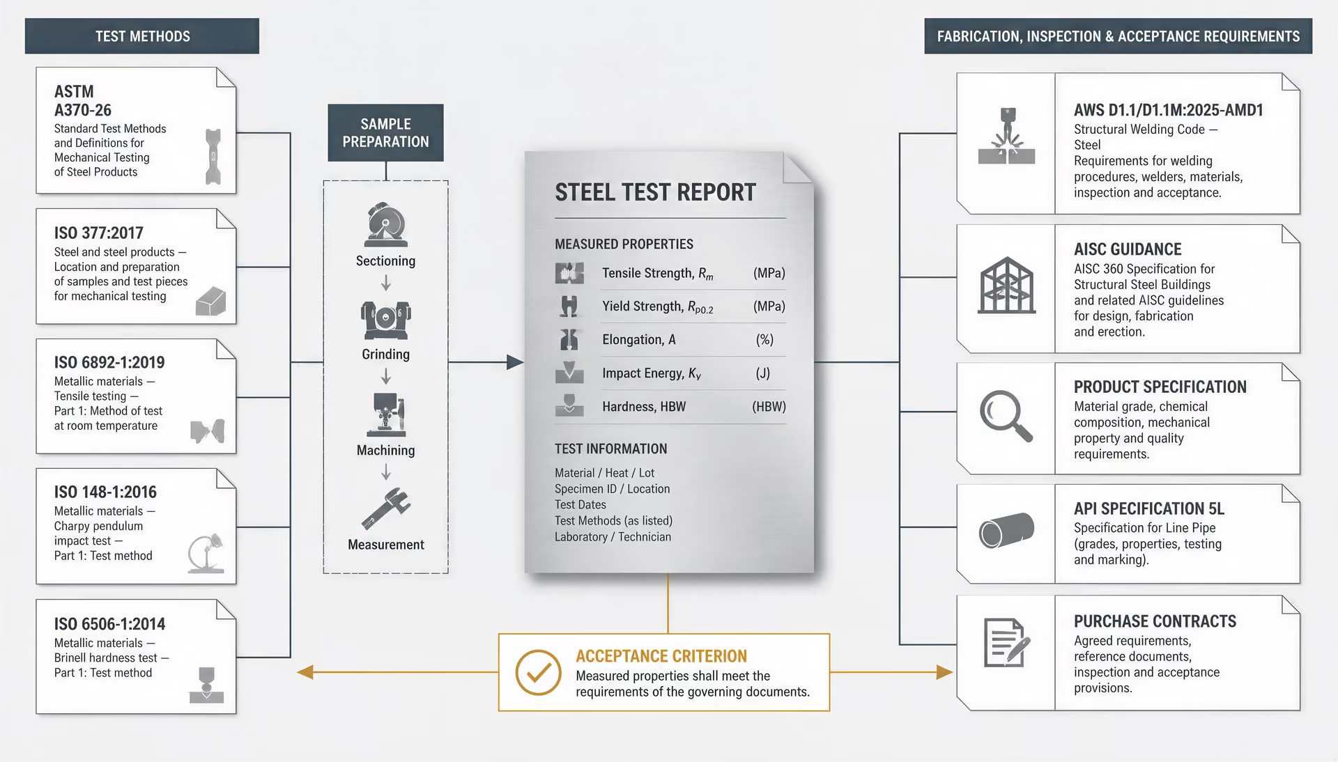
A steel test result has no independent pass-or-fail meaning. Its significance depends on a chain of references: the product being supplied, the location and orientation of the specimen, the test procedure, the reported property, and the document that sets the limit. ASTM A370-26 may prescribe how a tensile or impact test is performed, while an ASTM product specification, an API document, a project specification, or a purchase contract determines whether the measured value is acceptable. ISO standards can occupy the same chain, but they do not automatically replace ASTM requirements.
The distinction matters because standards organizations assign different jobs to their documents. ASTM and ISO primarily define test methods and specimen preparation. AWS D1.1/D1.1M:2025-AMD1 governs structural-steel welding, including qualification, fabrication, inspection, and weld acceptance. AISC provides design and inspection guidance rather than a universal replacement for a material specification. API Specification 5L connects pipe manufacture, testing, inspection, documentation, and purchasing requirements for pipeline transportation systems.
Standards that define measurements
ASTM A370-26 is a general mechanical-testing standard for steel, stainless steel, and related alloy products. It covers tension, bend, hardness, and impact testing, including procedural details that affect the result. Those details can include specimen dimensions, test equipment, preparation, test execution, and the way properties are reported. ASTM A370-26 does not, by itself, declare every steel heat or product acceptable. ASTM International states that acceptance comes from the applicable product specification or purchase contract.
ISO separates several functions that ASTM A370-26 presents within one general testing framework. ISO 377:2017 governs the identification, location, and preparation of samples and test pieces for mechanical testing of steel sections, bars, rod, flat products, and tubular products. It addresses where a piece is taken and how it is prepared. That is not the same question as how the test machine applies force.
ISO 6892-1:2019 specifies tensile testing of metallic materials at room temperature and identifies mechanical properties that may be determined. A report might include yield strength, tensile strength, elongation, or reduction of area, but the reported property must be tied to the specified test procedure and measurement conditions. A value obtained from a wrongly oriented specimen, an unsuitable gauge length, or a different strain-rate procedure is not made equivalent merely because it has the same unit.
Impact testing has its own method. ISO 148-1:2016 specifies pendulum impact testing with Charpy V-notch and U-notch specimens for determining absorbed impact energy in metallic materials. Notch geometry, specimen orientation, test temperature, and the number of specimens can affect the reported result. A contract requiring Charpy V-notch energy at a stated temperature cannot be satisfied by citing an unspecified impact result.
Hardness also requires a defined method. ISO 6506-1:2014 specifies the Brinell hardness test for metallic materials and applies to fixed-location and portable machines. The indenter, test force, surface condition, spacing, and measurement of the indentation all form part of the method. A hardness number without the scale and method is incomplete; “220 hardness” does not identify whether the result is Brinell, Rockwell, or a converted value.
ISO 18265:2013 provides conversion tables for hardness scales and tensile-strength estimates for unalloyed and low-alloy steels, cast steels, tool steels, and other metallic materials. Its conversions help compare results or support limited engineering assessment, but the standard warns that a converted value does not replace the result from the proper standard test method. A Brinell result converted to an estimated tensile strength is therefore not a substitute for a tensile test when the product specification requires tensile strength.
Codes that define fabrication and weld acceptance
Material testing and weld inspection answer different questions. A tensile test samples the mechanical behavior of a material or weld qualification specimen. Nondestructive examination seeks discontinuities in a finished weld or component without removing a test piece. Neither result can be interpreted correctly without the governing acceptance requirement.
AWS D1.1/D1.1M:2025-AMD1 establishes requirements for structural-steel welding. It addresses welding-procedure qualification, welder and welding-operator qualification, fabrication controls, inspection methods, and weld acceptance criteria. Its criteria apply to the weld categories and conditions within the code; they are not universal limits for every steel joint, pressure boundary, or pipeline girth weld.
AISC guidance identifies visual examination, dye-penetrant examination, magnetic-particle examination, radiographic examination, and ultrasonic examination as common nondestructive examination methods. It also identifies AWS D1.1/D1.1M Clause 8 as a source for weld inspection methods and acceptance criteria. The method must match the suspected discontinuity and joint configuration. Visual examination can identify surface profile, visible cracking, undercut, or dimensional problems, but it cannot establish the absence of internal planar flaws. Ultrasonic or radiographic examination may be required where the project documents call for volumetric examination.
AISC documents guide structural design, fabrication, and inspection within their stated scope; they do not turn every steel product into an AISC material. A W-shape, a welded connection, and a pipeline pipe may involve different material standards, design rules, and inspection clauses. The inspector must identify which document controls the component and which clause supplies the limit.
Product standards and purchasing requirements
Product standards establish the properties and conditions that a supplied item must meet. They may specify chemical composition, dimensions, heat treatment, tensile properties, impact energy, hardness, surface condition, supplementary tests, retesting, marking, and certification. The test method can come from ASTM A370-26 or an ISO document, while the product standard sets the minimum yield strength, tensile strength, elongation, or impact energy. This is why a laboratory certificate that says “tested to ISO 6892-1:2019” is incomplete if it does not identify the product designation and acceptance limits.
API Specification 5L concerns steel pipe for pipeline transportation systems. Its purchasing guidance stresses that procurement documents should identify the applicable manufacturing route, testing, inspection, and acceptance requirements. A purchaser may need to state the pipe product specification, grade or strength level, delivery condition, dimensions, pipe type, nondestructive examination requirements, hydrostatic testing, impact requirements, supplementary tests, and documentation. Without those selections, “API 5L pipe” may not communicate the full set of contractual obligations.
The same principle applies when documents are combined. ISO 377:2017 may govern specimen location, ISO 6892-1:2019 the tensile procedure, and a product standard the required strength and elongation. AWS D1.1/D1.1M:2025-AMD1 may govern a structural weld, with AISC project provisions defining when examination is required. API Specification 5L may add pipe-specific manufacturing and inspection provisions. These documents can work together, but they are not interchangeable. Replacing a specimen-preparation standard with a test-method standard, or replacing a weld-acceptance code with a material test report, breaks the link between measurement and acceptance.

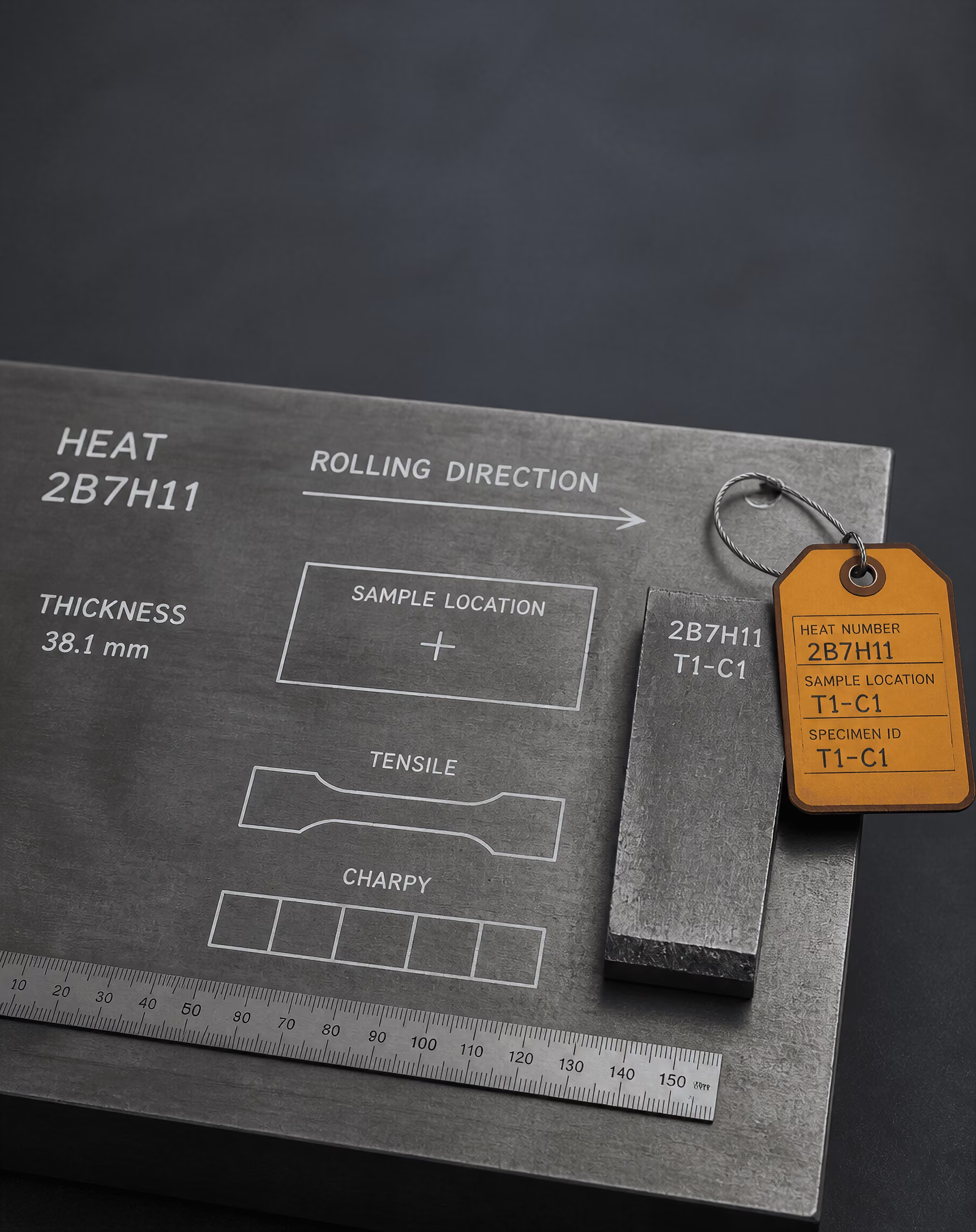
Sampling, Traceability, and Test-Piece Preparation
Heat, lot, product form, and specimen identity
A mechanical test result belongs to a defined piece of steel, not to a grade name by itself. “S355” or “ASTM A36” identifies a specification category, but it does not identify the heat, product thickness, rolling history, delivery condition, or precise location from which a specimen was removed. Two products carrying the same nominal grade designation may differ in segregation, grain structure, inclusion distribution, residual stress, and local properties. A test piece is therefore not representative merely because its certificate says the same grade as the material under examination.
ISO 377:2017 establishes the identification, location, and preparation of samples and test pieces for mechanical testing of steel sections, bars, rod, flat products, and tubular products. Its central practical requirement is continuity of identity. The laboratory must be able to connect the test piece to the sample, the sample to the product, and the product to the heat or lot recorded in the inspection documents.
- Material identity
- Supplier reference, heat or cast number, specification, and grade
- Product information
- Product form, nominal dimensions, and delivery condition
- Test identity
- Test-piece number, direction, method, and preparation
- Traceability
- Sample tied to product and product tied to heat or lot
A useful identity record normally includes the steelmaker or supplier reference, heat number, cast or melt number where applicable, product specification and grade, product form, nominal dimensions, delivery condition, and the location from which the sample was taken. It should also identify the test piece number, test direction, test method, and any preparation or deviation from the stated procedure. A report that lists “tensile test—S355” without a heat number and product location has lost information needed to judge whether the result applies to the supplied material.
The terms heat and lot are not interchangeable. A heat generally identifies steel produced from one controlled melt or cast. A lot may be defined by the product specification as a group of products made from one heat, one size range, one processing condition, or another stated combination. The applicable specification controls the definition. A sampling plan that treats an entire shipment as one lot when the governing standard separates heats, thickness ranges, or manufacturing routes can produce a formally neat but technically invalid result.
The connection between method and acceptance also matters. ASTM A370-26 provides procedures for tension, bend, hardness, and impact testing of steel, stainless steel, and related alloy products, but it does not decide whether a particular result passes. Acceptance comes from the applicable product specification or purchase contract (ASTM International, 2026). The specimen record must therefore preserve enough information to identify that specification, including its edition where relevant.
This principle extends beyond mechanical tests. API Specification 5L addresses steel pipe for pipeline transportation systems and calls for manufacturing, testing, inspection, and acceptance requirements to be specified for the ordered product (American Petroleum Institute, 2013). The pipe identity, manufacturing route, heat, pipe number, and inspection status must remain connected as samples are cut and dispatched. A laboratory cannot repair a broken chain of identification by producing a more precise hardness value.
Location and orientation within the product
Sampling location is a metallurgical variable. In a rolled plate, the center can contain a different inclusion population and segregation pattern from the surface. In a thick section, cooling rates and deformation may vary through the thickness. In a bar or rod, properties can differ between the center and the outer region. In tubular products, the wall position, weld location, seam orientation, and distance from an end may affect the result. These differences are why ISO 377:2017 covers product forms separately rather than treating all steel as a uniform block.
The product form must be recorded before the sample is taken. Relevant forms include structural sections, bars, rod, flat products such as plate and sheet, and tubular products. A tensile specimen cut from the flange of a section is not automatically equivalent to one cut from its web. A specimen from the mid-thickness of a plate is not automatically equivalent to a surface specimen. For tube, a sample from the parent metal is not interchangeable with one containing a longitudinal weld or heat-affected zone.
Orientation is equally important. “Longitudinal” commonly means that the principal axis of the test piece follows the rolling, drawing, extrusion, or pipe-production direction. “Transverse” means that it is perpendicular to that direction, subject to the definitions and permitted sampling positions in the governing standard. The direction must be marked on the product before cutting; it should not be inferred later from the shape of an unlabelled coupon.
Product specifications often require longitudinal or transverse tensile tests, bends, or impact specimens, and may prescribe the distance from a surface, edge, weld, or product end. When a plate specification requires a transverse tensile test, a longitudinal result cannot be substituted simply because the specimen was easier to machine. Similarly, Charpy specimens may need a specified orientation and notch direction so that the notch samples the intended microstructural plane. ISO 148-1:2016 defines the Charpy V-notch and U-notch pendulum impact method for determining absorbed impact energy, but the product specification determines the required orientation, temperature, number of specimens, and acceptance rule (International Organization for Standardization, 2016).
What a sampling record should show
- 1 Rolling or production direction.
- 2 Reference edge and product surface.
- 3 Weld or seam location where relevant.
- 4 Thickness position and cut boundaries.
- 5 Transferred markings, responsible person, and transfer time.
A sampling sketch or photograph is often more valuable than a general statement that the coupon came “from the plate.” It can show the rolling direction, reference edge, surface, weld or seam, thickness position, and cut boundaries. Markings should survive cutting where possible. If they cannot, the laboratory should transfer the identity immediately to the new sample and record who made the transfer and when.
Sampling must also reflect the question being asked. A certificate test may demonstrate compliance of a defined heat and product lot. An investigation of a failed component may require specimens from the fracture region, unaffected parent metal, weld metal, and heat-affected zone. Those are different populations. Combining them under one grade label can hide the location responsible for the failure.
Machining, notch preparation, and preservation of evidence
Preparation can change the measured property. Tensile specimens must be machined to the dimensions, gauge length, surface condition, and geometry required by the selected method. ISO 6892-1:2019 specifies tensile testing of metallic materials at room temperature and the mechanical properties that may be determined, but the result depends on a correctly prepared specimen and accurate dimensional measurements (International Organization for Standardization, 2019). Excessive grinding, deep tool marks, overheating, or an incorrect transition radius can create premature fracture or alter the reported elongation.
The same caution applies to hardness. ISO 6506-1:2014 specifies the Brinell method for metallic materials, including tests made with fixed-location and portable machines. The test surface must be suitable for the indentation and the location must be recorded. A hardness value taken from scale, decarburized material, a weld bead, or a surface affected by grinding may answer a different question from hardness in the parent metal. ISO 18265:2013 supplies hardness conversions and tensile-strength estimates for specified metallic materials, including unalloyed and low-alloy steels, but states that converted values do not replace results from the proper standard test method (International Organization for Standardization, 2013). A converted Brinell value should not be presented as a tensile test.
Notch preparation requires still tighter control. For Charpy testing, the notch geometry, notch orientation, notch position, and surface finish determine where fracture initiates. The notch must be placed in the specified direction and region; a reversed notch can expose a different microstructural plane. The specimen should be protected from damage to the notch and from mix-up with specimens from another heat or location. Labels, diagrams, and photographs should record the notch direction before testing, not after a broken half has been separated from its identity.
Cutting methods also deserve a record. Flame cutting, sawing, shearing, machining, and electrical-discharge methods may leave different heat-affected layers, deformation, or residual stresses. The governing product or test standard may specify how much material must be removed before final machining. If preparation departs from that requirement, the deviation belongs in the report. It is evidence about the test, not an administrative detail.
Preserve the parent material and the rejected fragments when a result is disputed or a failure is under investigation. Keep the original markings, offcuts, broken tensile ends, Charpy halves, hardness photographs, and machining records under the same specimen identity. For welded products, retain macrographs or surface photographs showing the weld, fusion boundary, and heat-affected zone where relevant. Nondestructive examination does not replace this chain. AISC identifies visual, dye-penetrant, magnetic-particle, radiographic, and ultrasonic examination as common methods, while AWS D1.1/D1.1M:2025-AMD1 sets structural-steel welding requirements for qualification, fabrication, inspection, and weld acceptance criteria (American Welding Society, 2025; American Institute of Steel Construction, 2024).
The final report should state what was tested, where it came from, how it was oriented, how it was prepared, which method was used, and which specification supplied the acceptance criterion. Only then can a reported number be compared with the correct requirement.
Chemical Identity and the Limits of Mechanical Testing
Grade designation and material identity
A steel grade is not defined by one tensile result. Its identity rests first on the material designation and chemical composition stated by the applicable product standard. Mechanical properties then show whether the material, in its supplied condition, meets that standard’s performance requirements.
The distinction matters because similar strength values can occur in different alloys. ASTM A36/A36M structural carbon steel, ASTM A572/A572M Grade 50 high-strength low-alloy steel, and ASTM A240/A240M Type 304 stainless steel may all produce acceptable tensile results for a particular project, yet they are not interchangeable materials. Their alloying systems, corrosion behavior, welding considerations, product forms, and required acceptance criteria differ. A tensile report that records a yield strength of 350 MPa does not identify which of those grades was tested.
The designation must therefore be read as a complete statement, not as an isolated number or trade description. It may include the governing standard, grade, class, type, product form, thickness range, delivery condition, supplementary requirements, and heat-treatment condition. “Grade 50” without its standard and product form is incomplete. The same numerical designation can have different requirements under different specifications.
Chemical verification addresses this identity question. A heat or product analysis normally records elements such as carbon, manganese, phosphorus, sulfur, silicon, chromium, nickel, molybdenum, copper, niobium, vanadium, or titanium, as applicable to the grade. The limits are specified by the product standard, while the reported analysis must be connected to the material represented by the test certificate. A positive match is not established merely because the material is strong enough.
ASTM A370-26 defines procedures for tension, bend, hardness, and impact testing of steel, stainless steel, and related alloy products, but it does not assign one universal pass-fail limit to every steel. ASTM International states that acceptance is determined by the applicable product specification or purchase contract (ASTM International, 2026). The test method and the acceptance requirement are separate parts of the control system.
Why mechanical tests cannot replace chemical verification
Tensile testing measures properties such as yield strength, tensile strength, elongation, and reduction of area under a specified procedure. ISO 6892-1:2019 specifies tensile testing of metallic materials at room temperature and the mechanical properties that may be determined (International Organization for Standardization, 2019). It does not determine the full alloy chemistry or prove that the specimen carries the claimed grade designation.
Bend testing examines ductility and the occurrence of cracks under a specified former and angle. Hardness testing measures resistance to indentation. ISO 6506-1:2014 specifies the Brinell method for metallic materials, including fixed-location and portable machines (International Organization for Standardization, 2014). Impact testing measures absorbed energy under a defined notch, temperature, and pendulum arrangement; ISO 148-1:2016 covers Charpy V-notch and U-notch testing (International Organization for Standardization, 2016). None of these results is a chemical fingerprint.
A hardness value may be converted into an estimated tensile strength, but that estimate cannot replace the specified tensile test. ISO 18265:2013 provides hardness conversions and tensile-strength estimates for selected unalloyed and low-alloy steels, cast steels, tool steels, and other metallic materials, while warning that converted values do not replace results from the proper standard test method (International Organization for Standardization, 2013). The same limitation applies more strongly when trying to infer grade from hardness alone.
Heat treatment illustrates the problem. Quenching and tempering can raise strength in a steel whose chemistry differs from another steel that reaches a similar strength through alloying or processing. Cold work can alter hardness and yield strength without changing bulk composition. Thickness, sampling location, grain structure, segregation, and test temperature also affect the reported result. A technically correct tensile test can therefore describe the specimen accurately while saying nothing conclusive about whether it was ASTM A516/A516M Grade 70, ASTM A572/A572M Grade 50, or another material with overlapping properties.
Specimen control is equally important. ISO 377:2017 specifies identification, location, and preparation of samples and test pieces for mechanical testing of steel sections, bars, rod, flat products, and tubular products (International Organization for Standardization, 2017). If the wrong plate, thickness, orientation, or product location is sampled, the laboratory may follow the method correctly and still produce a result that cannot be applied to the claimed material.
Heat-level documentation and mixed-material risks
The practical link between identity and performance is the heat number. A heat is a defined quantity of steel produced from a particular melting operation or production record. The mill test report, material test report, or certificate should connect the heat number to the product identification, grade, dimensions, condition, chemical analysis, mechanical test results, and any required supplementary tests. That connection must survive cutting, processing, storage, and installation.
A certificate for Heat H12345 cannot automatically support a plate marked H12345A, a remnant with no retained marking, or a bundle containing several heats. Marking systems can be removed by blasting, cutting, coating, or fabrication. Once traceability is lost, a later tensile test does not restore it. It confirms the properties of the tested piece, not its origin or complete chemical identity.
Mixed-material storage creates a similar risk. Plates of ASTM A36/A36M and ASTM A572/A572M Grade 50 may look identical and may produce overlapping bend or hardness results. A stainless steel and a carbon steel component can also be confused after surface preparation removes visible markings. If a sample is taken from the wrong item, the laboratory’s report may be accurate but assigned to the wrong heat.
This is why chemical analysis, markings, certificates, and mechanical reports must be reviewed as one traceability chain. For pipeline steel pipe, API Specification 5L purchasing guidance addresses the need to specify manufacturing, testing, inspection, and acceptance requirements rather than relying on a generic test result (American Petroleum Institute, 2013). In structural welding, AWS D1.1/D1.1M:2025-AMD1 separately establishes welding procedure qualification, welder qualification, inspection methods, and weld acceptance criteria (American Welding Society, 2025). A weld inspection cannot correct an unidentified base metal.
The correct conclusion is limited but important: mechanical testing establishes measured performance for a properly identified specimen. Chemical verification establishes what the material is. Neither function can replace the other.

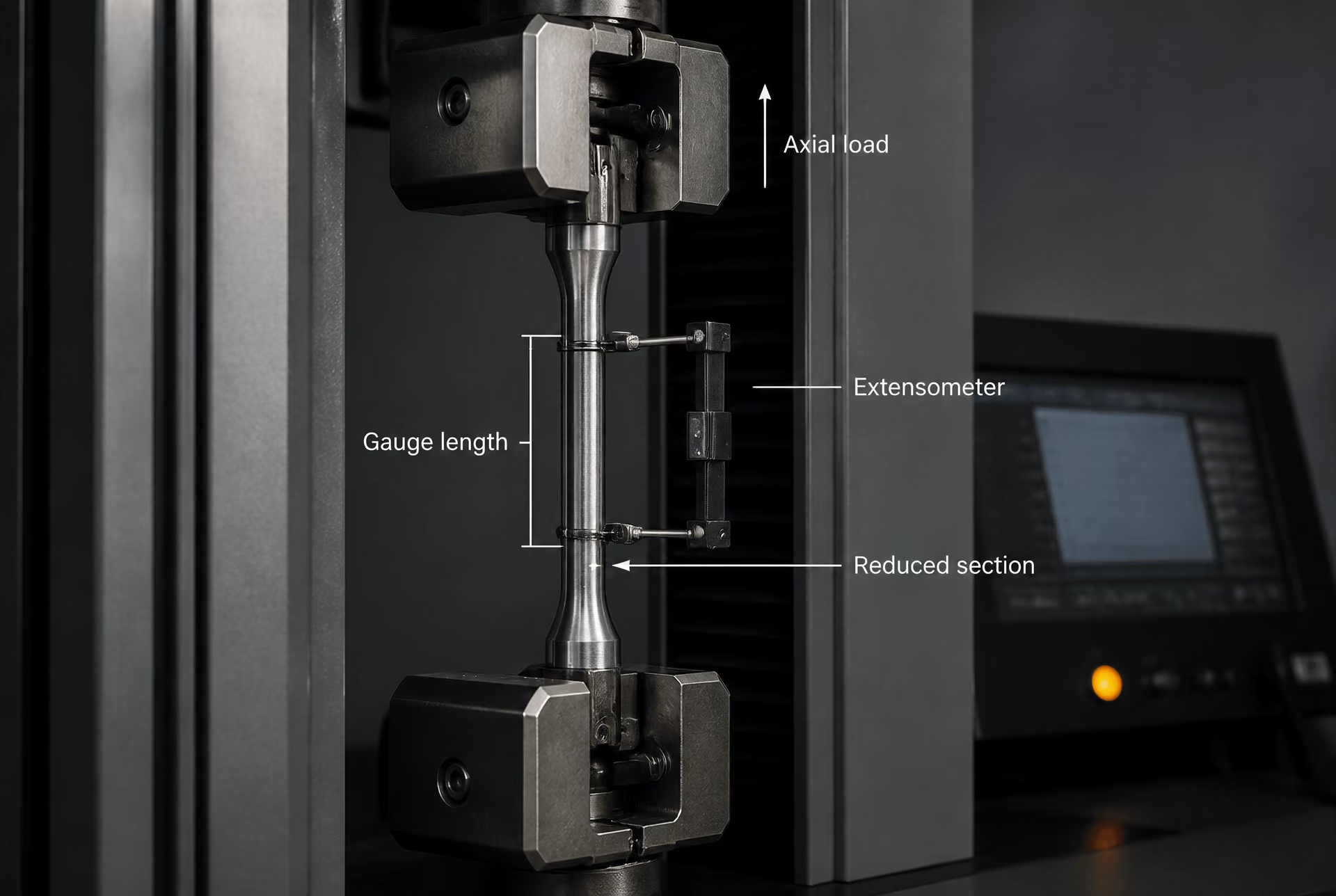
Tensile Testing of Steel at Room Temperature
Tensile testing measures how a steel specimen responds to a steadily increasing axial load at room temperature. The test can show the stress at which plastic deformation begins, the maximum engineering stress reached, and the amount of permanent deformation before fracture. Those results help characterize a heat, plate, bar, tube, forging, or other product, but the test is not a universal pass-or-fail decision. A result becomes meaningful only when the reported value is tied to the correct product form, sampling location, specimen geometry, test standard, and acceptance requirement.[7] ISO 6892-1:2019. International Organization for Standardization. ISO standard, 2019.
The distinction matters because a test laboratory may follow a valid tensile procedure while an inspector applies the wrong product specification. Conversely, a product specification may require a result that cannot be obtained reliably from an unsuitable specimen or an incorrectly controlled test. ASTM A370-26 covers tension, bend, hardness, and impact testing of steel, stainless steel, and related alloy products, while leaving acceptance to the applicable product specification or purchase contract (ASTM International, 2026). ISO 6892-1:2019 specifies tensile testing of metallic materials at room temperature and identifies the mechanical properties that may be determined (International Organization for Standardization, 2019).
ISO 6892-1:2019 and ASTM A370-26
ISO 6892-1:2019 is a general method for tensile testing metallic materials at room temperature. It addresses preparation and marking of test pieces, test-machine requirements, force and extension measurement, test rates, determination of properties, and reporting. It provides the framework for obtaining comparable results, rather than setting the minimum yield strength or elongation for every steel grade.
ASTM A370-26 serves a similar coordinating function for many steel and alloy products in ASTM-based inspection systems. Its tension-test provisions must be read with the relevant material specification. For example, the applicable specification may identify whether the result is reported as yield strength or yield point, whether a specified extension is used to determine proof strength, which elongation gauge length applies, and whether reduction of area is required. The test method supplies the procedure; the product specification supplies the requirement.
Specimen selection is part of that link. ISO 377:2017 governs identification, location, and preparation of samples and test pieces for mechanical testing of steel sections, bars, rod, flat products, and tubular products. A product may require a longitudinal specimen, a transverse specimen, or a specimen taken from a defined position through the thickness. A plate specimen cut parallel to the rolling direction does not necessarily represent the same directional behavior as one cut transverse to it. A tube may require attention to curvature, wall thickness, flattening, and the location of the test piece. The laboratory should record the parent product, heat or cast identification, orientation, thickness or diameter, and sampling position.
The specimen’s reduced section must have a defined geometry, with a gauge length used for extension measurements. Standardized dimensions make elongation results comparable. They do not make every geometry interchangeable. A proportional specimen and a non-proportional specimen can produce different percentage elongations because the final strain is not distributed independently of gauge length and cross-sectional shape. Machining also matters: deep tool marks, sharp transitions, overheating, decarburization, or an incorrect surface condition can create an early fracture or alter the measured ductility.
The test machine must apply tensile force through the specimen’s axis and measure force and extension accurately over the required range. Gripping should prevent slip without crushing, bending, or introducing a stress concentration near the grips. Alignment errors can produce bending stresses that are not part of the intended uniaxial test. The procedure also controls the rate of loading or strain. Excessive speed can affect the apparent yield behavior and the measured extension, while an unnecessarily slow or inconsistent rate can make results difficult to compare.
An extensometer measures extension over a defined gauge length. It is not simply a device for making the test more precise; its gauge length, attachment, range, resolution, calibration, and removal point affect which property can be determined. An extensometer used to determine yield or proof behavior must remain attached and accurate through the relevant part of the stress–strain curve. If it is removed before fracture, the machine’s crosshead movement cannot automatically substitute for gauge-length extension, because crosshead displacement also includes deformation in the grips, machine frame, and other components. The test record should state how extension was measured and when the extensometer was removed, if removal was permitted by the method.
Yield strength, proof strength, tensile strength, elongation, and reduction of area
| Property | What it describes | Important reporting condition |
|---|---|---|
| Yield strength | Stress associated with onset of plastic deformation | State whether a distinct yield point or another definition was used |
| Proof strength | Stress associated with a specified permanent strain | State the specified offset or extension |
| Tensile strength | Maximum engineering stress reached | Calculated using the original cross-sectional area |
| Elongation | Extension over a defined gauge length | Gauge length must accompany the percentage |
| Reduction of area | Decrease in cross-sectional area at fracture | Measured at the neck and reported separately |
Yield strength describes the stress associated with the onset of plastic deformation. Some steels show a distinct upper and lower yield point: the material reaches a peak stress, then continues plastic deformation at a lower, relatively stable stress. Other steels do not display a clear yield point. Their stress–strain curve changes gradually from elastic to plastic behavior, so a specified offset or extension is used to define a reproducible value.
Proof strength is an offset-based measure of plastic deformation. A designation such as proof strength at a specified percentage strain refers to the stress required to produce that permanent strain under the defined method. The exact offset must come from the applicable standard or product specification. Proof strength is therefore not interchangeable with a visually identified yield point, and it should not be reported under a generic “yield” label when the governing requirement calls for proof strength.
Tensile strength, often called ultimate tensile strength, is the maximum engineering stress reached during the test. It is calculated from the highest recorded force divided by the original cross-sectional area. After this maximum, a ductile specimen commonly develops localized necking. The actual load can fall even while the material in the neck continues to undergo plastic deformation. Tensile strength consequently does not mean the stress at fracture, nor does it indicate the amount of ductility by itself.
Elongation measures extension over the specified gauge length after fracture, usually expressed as a percentage of the original gauge length. The fractured pieces are fitted together, and the final gauge length is measured according to the governing method. Elongation depends strongly on gauge length, specimen geometry, orientation, thickness, surface condition, and the distribution of plastic strain. A short gauge length may include more of the localized necking strain and can produce a different percentage than a longer gauge length. The gauge length must accompany the reported value.
Reduction of area measures the decrease in cross-sectional area at the fracture location. It is calculated by comparing the original area with the smallest final area at the neck, then expressing the difference as a percentage of the original area. Unlike elongation, it focuses on local contraction rather than total extension over a defined length. Two specimens may have similar elongation but different reduction of area, or similar reduction of area but different elongation. Neither property replaces the other.
The stress values also depend on the area convention. Engineering stress uses the original area, whereas true stress uses the changing area during deformation. Product specifications and routine tensile reports generally identify the convention required by the test standard. A laboratory should not mix values calculated by different conventions or infer a grade-specific limit from a graph without checking the governing document.
Fracture location, specimen validity, and reporting
A fracture in the reduced section is normally the expected outcome, but its precise location affects the validity of elongation and may raise questions about the other results. A break close to a grip, outside the gauge length, at a machining mark, or at an obvious misalignment defect may not represent the material’s gauge section. The applicable method and product specification determine whether the result is invalid, whether a special condition permits acceptance, or whether a retest is required. The laboratory should not quietly discard an inconvenient result or replace it with a retest without recording the reason.
Fracture appearance can also provide useful observations. A centered, ductile neck differs from a shear break, split, lamination-related failure, or fracture originating at a surface defect. Appearance alone does not establish compliance, but it can signal a specimen-preparation problem, a product discontinuity, or an abnormal failure mode. The fracture location, distance from the nearest gauge mark or grip, and any visible defect should be recorded when relevant.
A defensible report identifies the material designation, product form, heat or cast number, specimen orientation, sampling location, specimen type and dimensions, original cross-sectional area, gauge length, test temperature, test method and edition, loading or strain-rate basis, force and extension equipment, and any deviations. It reports the determined properties with units and states whether elongation was measured after fracture and whether reduction of area was determined. If a specimen fractured outside the permitted location, that fact belongs in the report even if a retest is later performed.
Most importantly, the report should separate measured results from acceptance status. ISO 6892-1:2019 can produce a tensile strength, proof strength, and elongation, but it does not decide whether a particular grade passes. ASTM A370-26 likewise directs users to the applicable product specification or purchase contract for acceptance. A structural plate specification, a pressure-vessel material specification, and a line-pipe requirement may prescribe different specimen locations, properties, and limits for steels with similar nominal chemistry. API Specification 5L, for example, addresses steel pipe for pipeline transportation systems and the need to define manufacturing, testing, inspection, and acceptance requirements (American Petroleum Institute, 2013). The acceptance value must therefore be cited from the governing product specification, revision, and purchase document—not invented from the tensile method or borrowed from another grade.
Bend Testing: Ductility, Soundness, and Surface Opening
Guided bend and bend-test objectives
A bend test asks whether a steel specimen can undergo a specified amount of plastic deformation without developing an unacceptable opening on the tension side. It is therefore a ductility and fabrication-soundness assessment, not a substitute for tensile testing. A tensile test measures properties such as yield strength, tensile strength, elongation, and reduction of area under a controlled axial load. ISO 6892-1:2019 specifies that room-temperature tensile method and the mechanical properties that may be determined. A bend test supplies a different type of evidence: it concentrates strain through a curved section and exposes surface-breaking weaknesses that may not be apparent from a tensile result.
The distinction matters because a steel can satisfy its tensile-strength and elongation requirements yet fail a bend test. Localized inclusions, laminations, porosity, weld discontinuities, unfavorable grain flow, or surface defects may open when the specimen is wrapped around a former. Conversely, a bend-test pass does not establish the tensile strength required for a grade such as ASTM A36 or ASTM A572 Grade 50. Each test answers a defined question.
ASTM A370-26 provides procedures for tension, bend, hardness, and impact testing of steel, stainless steel, and related alloy products. It does not create one acceptance rule for every steel product. ASTM International states that acceptance is determined by the applicable product specification or purchase contract (ASTM International, 2026). The relevant specification might be a plate, bar, sheet, tube, pipe, or welding standard, and its requirements can change with thickness, grade, product form, or condition of supply.
Specimen selection is part of the result. ISO 377:2017 addresses identification, location, and preparation of samples and test pieces for steel sections, bars, rod, flat products, and tubular products. A correctly performed bend on the wrong location or orientation can give a misleading indication of product quality. The test record should identify the heat or lot, product form, grade, thickness, specimen dimensions, surface condition, bend direction, former diameter, bend angle, and observed indication.
Bend tests are also used in welding qualification and fabrication control. AWS D1.1/D1.1M:2025-AMD1 includes requirements for structural-steel welding, procedure and welder qualification, fabrication, inspection methods, and weld acceptance criteria. A transverse weld bend, longitudinal weld bend, or side bend does not assess exactly the same region of a joint. The selected specimen must place the weld metal, fusion boundary, heat-affected zone, or root where the applicable qualification requirement intends it to be.
Mandrel, angle, orientation, and bend location
Former or mandrel The tool around which a bend specimen is formed; its diameter and the bend angle control the imposed deformation.
The former, or mandrel, controls the severity of deformation. In many specifications it is expressed as a diameter related to specimen thickness, such as a former diameter of a specified multiple of t. A smaller diameter produces a tighter bend and greater outer-fiber strain; a larger diameter imposes a less severe condition. The stated diameter alone is not enough. The specimen width, thickness, machined edges, bend angle, and method of applying force also affect the strain imposed on the material.
A guided bend commonly places the specimen across a die opening while a plunger forces it around a prescribed former. The finished angle may be 90°, 120°, 180°, or another value set by the governing requirement. A 180° bend is not automatically the correct or most severe test for every product. The product specification controls. ASTM A370-26 supplies the general procedure, while the grade or product standard supplies the dimensions and acceptance condition.
Orientation is equally important. A flat-product specimen may be bent transverse or longitudinal to the rolling direction. A bar or section can require a particular relationship to its longitudinal axis. For welded material, the face, root, or side may be placed in tension. The tension surface is where an existing discontinuity is most likely to open, so changing the bend direction changes what the test reveals. A transverse face bend places the weld face on the outside of the bend; a root bend places the root side there. A side bend exposes a cross-section and can reveal discontinuities distributed through the weld thickness.
The bend location must also be controlled. A plate specimen may be taken from the mid-thickness region, near a surface, from a prescribed end, or at a specified distance from a weld. Tubular products introduce additional choices, including strip orientation around the circumference and whether the test evaluates the pipe body or a weld seam. API Specification 5L concerns steel pipe for pipeline transportation systems and emphasizes specifying manufacturing, testing, inspection, and acceptance requirements rather than relying on an undefined generic test (American Petroleum Institute, 2013).
Preparation can alter the apparent result. Flame-cut edges, rough sheared edges, sharp corners, grinding marks, or excessive machining can act as artificial crack starters. The applicable standard may require rounded edges or limit edge dressing. The laboratory should record whether an opening began at a prepared edge, at the original product surface, in weld metal, or in the heat-affected zone. That location can determine whether the indication is relevant to the specified acceptance rule.
Cracks, tears, and specification-defined discontinuities
“Crack” is not a complete acceptance decision. The inspector must determine where it formed, how it appears, and which document governs the result. One product specification may reject any crack or tear visible after bending. Another may permit limited edge tearing while rejecting openings in the weld face or base metal. A welding qualification provision may define a maximum permitted discontinuity length, exclude certain types of indications, or require evaluation of several specimens. There is no universal crack-size rule that can be applied to all steel bend tests.
| Bend observation | Why location matters | Acceptance basis |
|---|---|---|
| Clean surface | No visible opening under the stated condition | Product specification or welding requirement |
| Edge tear | May relate to specimen-edge preparation | Specific edge-discontinuity rule |
| Longitudinal opening | May expose a product discontinuity | Applicable product or fabrication criterion |
| Weld-metal cracking | Indicates a weld-region issue | Applicable weld code or qualification rule |
| Fusion-boundary opening | May indicate an interface discontinuity | Weld acceptance criterion |
Typical observations include a clean surface, a shallow edge tear, a longitudinal opening, a transverse crack, laminarlike separation, weld-metal cracking, or an opening at the fusion boundary. Their significance differs. A small discontinuity caused solely by specimen-edge preparation may be treated differently from a crack that initiates on the original rolled surface. A long, sharp opening in the tension region usually carries more significance than a short rounded mark, but the final decision still belongs to the applicable specification.
The report should describe indications rather than merely state “pass” or “fail.” It should give the measured or estimated length, orientation, surface on which it appeared, distance from an edge, and whether it is continuous or separated. Photographs can help preserve evidence, especially when a product specification requires review by the purchaser or engineer. If the requirement is unclear, the test should not be retroactively judged against a convenient limit.
Bend testing also differs from nondestructive examination after fabrication. Visual examination, dye-penetrant testing, magnetic-particle testing, radiographic testing, and ultrasonic testing inspect welds without cutting and bending a specimen; AISC identifies these as common NDE methods and points to AWS D1.1/D1.1M Clause 8 for weld inspection methods and acceptance criteria (American Institute of Steel Construction, 2024). A bend test may reveal a fabrication weakness by forcing it open, but it does not map the full production weld or replace the examination required by the construction specification.
The defensible result is therefore a linked chain: the correct product and grade, a representative specimen identified and prepared under the applicable sampling standard, the specified orientation and bend location, the stated mandrel and angle, and an acceptance criterion taken from the governing product specification, welding code, or contract. ASTM A370-26 establishes the test framework; it does not turn every visible opening into the same kind of failure.
Hardness Testing: Brinell Measurement and Interpretation
ISO 6506-1:2014 and Brinell hardness testing
Brinell hardness testing measures the resistance of a metallic surface to penetration by a hard spherical indenter. The machine applies a specified force through a tungsten-carbide ball, holds that force for a defined period, removes it, and measures the diameter of the permanent impression in two approximately perpendicular directions. The Brinell hardness number is calculated from the test force and the curved surface area of the impression, not from impression diameter alone. A smaller impression under the same test conditions indicates greater resistance to indentation and therefore a higher Brinell value.
The result is normally reported using the designation HBW, followed by the ball diameter, test force, and, where required, force-application time. A result such as 210 HBW 10/3000 identifies a Brinell hardness value obtained with a 10 mm tungsten-carbide ball and a 3000 kgf nominal test force. Reporting only “210 Brinell” removes information needed to judge whether another result was obtained under comparable conditions.[8] ISO 6506-1:2014. International Organization for Standardization. ISO standard, 2014.
ISO 6506-1:2014 specifies the Brinell test method for metallic materials and covers both fixed-location and portable hardness-testing machines (International Organization for Standardization, 2014). The selected ball diameter and force are not arbitrary. The force-to-ball-diameter relationship affects impression size and sensitivity, so a valid comparison normally requires the same Brinell scale or a scale permitted by the applicable product standard. The operator must also apply the force without damaging the surface, maintain it for the specified dwell time, and measure a clearly defined impression.
A Brinell number is a measured hardness property, not a direct statement of tensile strength, yield strength, wear life, or service performance. Steel with a higher hardness value often has higher strength, particularly within related grades and heat-treatment conditions, but the relationship depends on composition, microstructure, prior processing, and the relevant test range. ISO 18265:2013 provides hardness conversions and tensile-strength estimates for specified metallic materials, including unalloyed and low-alloy steels, cast steels, and tool steels. It also warns that a converted value does not replace the result of the proper standard test method (International Organization for Standardization, 2013). A reported conversion therefore cannot cure a missing or incorrectly selected tensile test.
The hardness result is meaningful only when linked to the product specification. ASTM A370-26 gives procedures for hardness testing, along with tension, bend, and impact testing of steel, stainless steel, and related alloy products, but it leaves acceptance to the applicable product specification or purchase contract (ASTM International, 2026). A result of 210 HBW can comply with one grade, heat-treatment condition, or order requirement and fail another. The number alone is not an acceptance criterion.
Fixed-location and portable machines
A fixed-location machine is commonly installed on a rigid support in a laboratory or inspection area. Its frame limits movement during loading, its anvil and test head can be aligned with greater control, and its optical or electronic system can make impression measurement more repeatable. These features reduce variation, but they do not eliminate errors caused by poor preparation, curved surfaces, unsuitable thickness, an incorrect force, or an impression placed too close to another impression.
Portable Brinell machines are within the scope of ISO 6506-1:2014. That inclusion does not make every field reading interchangeable with a laboratory result. Portable equipment must still apply the specified force, use the required indenter, maintain alignment, and permit measurement of the impression in accordance with the method. The workpiece must provide a sufficiently stable reaction point. Vibration, movement, local curvature, limited access, paint, scale, and rough grinding can all affect the reading.
Field testing requires stronger location control because the machine is taken to the product rather than the product being brought to a controlled test station. The report should identify the product, heat or cast, test face, grid or reference location, machine identification, indenter and force, individual readings, calculated result, and any surface preparation. Photographs or marked-up drawings may be appropriate for large plate, forgings, weldments, or installed components. “Portable hardness: pass” is inadequate documentation if nobody can determine where the readings were taken or which scale was used.
The test location also matters metallurgically. Surface hardness may differ between a quenched layer and the underlying material, between the edge and center of a bar, or between base metal, heat-affected zone, and weld metal. ISO 377:2017 addresses identification, location, and preparation of samples and test pieces for mechanical testing of steel sections, bars, rod, flat products, and tubular products (International Organization for Standardization, 2017). It is not a substitute for the Brinell method, but it illustrates the broader principle: specimen location is part of the test definition.
Surface condition, spacing, thickness, and repeatability
The surface must be sufficiently smooth and clean for the impression boundary to be identified. Rust, scale, decarburized material, coatings, oil, weld spatter, and machining marks can distort the indentation or obscure its edge. Preparation should remove surface irregularities without producing excessive heating, cold work, or a new hardened layer. Heavy grinding can change the very material being measured. A polished laboratory surface and a lightly ground field surface may produce different levels of measurement uncertainty even when both appear visually acceptable.
The test face should be reasonably flat and supported. On a curved surface, the apparent impression geometry changes because the surface is not a plane. A small-diameter bar, thin strip, or irregular forging may therefore require another hardness method or a product-specific procedure rather than an unqualified Brinell reading.
Impressions must be separated from one another and from edges. ISO 6506-1:2014 specifies minimum spacing requirements in relation to the impression diameter and minimum distance from an edge. In commonly applied Brinell arrangements, centers are separated by at least three impression diameters and an impression center is at least 2.5 diameters from an edge; the exact applicable requirement must be checked against the adopted edition and test condition. A nearby impression plastically deforms the surrounding material and can change the second reading. An edge can allow material to flow outward, usually producing an impression that does not represent the interior hardness.
Thickness is equally important. The material beneath the indentation must be thick enough that the plastic zone does not reach the opposite face. ISO 6506-1:2014 sets a minimum thickness relationship to impression depth; a commonly used rule for standard Brinell conditions is a thickness of at least eight times the impression depth. Thin products may show an artificially low or unstable result if the reverse face is too close. The product specification can impose a stricter limit or require another method.
Repeatability should be judged from individual impressions, not just their average. A sensible procedure records each reading, checks whether the impressions satisfy spacing and geometry requirements, and investigates an outlier rather than silently deleting it. Variation may indicate changing microstructure, a weld or heat-affected zone, inadequate support, machine misalignment, surface damage, or operator measurement error. Repeated impressions in one uniform region should cluster within the repeatability limits of the machine and method; broad scatter is evidence that the test arrangement needs review.
Finally, hardness testing must remain separate from other acceptance examinations. Tensile testing under ISO 6892-1:2019 determines properties such as yield strength and tensile strength, while ISO 148-1:2016 specifies Charpy pendulum impact testing for absorbed energy. Neither test is replaced by Brinell hardness. The applicable material standard, fabrication code, or contract must state which property governs acceptance and what hardness limits, if any, apply.
Hardness Conversions and the Danger of Back-Calculating Strength
A hardness number is not a tensile-test result expressed in different units. Brinell, Rockwell, and Vickers tests measure resistance to localized indentation, whereas a tensile test measures the response of a prepared specimen under controlled axial loading. The relationship between those results is empirical and depends on material, condition, test scale, and the range covered by the conversion data.
That distinction matters when a mill certificate, inspection report, or nonconformance review uses hardness to infer yield strength or tensile strength. A converted value may help assess whether a result is plausible. It does not automatically establish compliance.
ISO 18265:2013 conversion tables
ISO 18265:2013 provides conversion tables between specified hardness scales and tables for estimated tensile-strength values. Its scope includes unalloyed and low-alloy steels, cast steels, tool steels, and other metallic materials. The standard does not declare Brinell, Rockwell, Vickers, and tensile strength to be interchangeable properties. It presents relationships developed for defined material groups and specified ranges.
| Method | Measured response | Typical identifying notation |
|---|---|---|
| Brinell | Permanent impression from a spherical indenter | HBW |
| Rockwell | Depth of penetration under defined loads | HRB or another Rockwell scale |
| Vickers | Diagonals of a diamond-pyramid indentation | HV |
| Tensile test | Axial loading response of a prepared specimen | Yield strength or tensile strength in MPa |
The test methods themselves differ. ISO 6506-1:2014 specifies Brinell hardness testing, in which a ball indenter produces an impression and the result is calculated from the applied force and impression diameter. Rockwell testing determines depth of penetration under defined preliminary and total loads, with the scale depending on the indenter and force combination. Vickers testing uses a diamond pyramid and calculates hardness from the two diagonals of the indentation. A value such as 210 HBW, 95 HRB, or 220 HV therefore records a response obtained by a particular method; it is not a set of identical measurements that can be exchanged without qualification.
ISO 18265:2013 also separates hardness-scale conversions from tensile-strength estimates. A table may associate a Vickers or Brinell range with an estimated tensile strength for a listed steel category, but that estimate is not a direct observation of ultimate tensile strength. The relationship can shift with carbon content, alloying, heat treatment, cold work, microstructure, section size, and product form. A normalized plate and a quenched-and-tempered bar can show similar local hardness while developing different tensile-test results, particularly when their microstructures and strength gradients differ.
The standard’s warning is decisive: converted values do not replace results obtained by the proper standard test method. That warning should appear in the interpretation of the report, not disappear behind a rounded number.
Converted values versus direct tensile results
A direct tensile result requires the correct specimen, dimensions, orientation, gauge length, strain measurement, and loading procedure. ISO 6892-1:2019 specifies tensile testing of metallic materials at room temperature and identifies the mechanical properties that may be determined, including quantities such as yield strength and tensile strength. ISO 377:2017 governs identification, location, and preparation of samples and test pieces for mechanical testing of steel sections, bars, rod, flat products, and tubular products. These details affect what the result represents.
Hardness testing has a different sampling problem. An indentation samples a small volume near the test surface. It may reveal local heat treatment or surface processing that a tensile specimen averages over a much larger gauge section. A portable hardness test can be useful for field screening, but surface curvature, roughness, scale, decarburization, indentation spacing, support, and machine verification can affect the reading. Converting that reading into tensile strength adds another source of uncertainty.
Reports should preserve the measurement chain. “210 HBW, ISO 6506-1:2014” identifies a Brinell result. “Estimated tensile strength: approximately [value] MPa by ISO 18265:2013” identifies a derived estimate, provided the applicable material table and range are stated. It should not be reported simply as “tensile strength: [value] MPa,” because that wording implies a tensile test under ISO 6892-1:2019 or another specified tensile method.
The same discipline applies to acceptance decisions. ASTM A370-26 covers tension, bend, hardness, and impact testing of steel, stainless steel, and related alloy products, but acceptance is determined by the applicable product specification or purchase contract (ASTM International, 2026). A hardness conversion cannot silently replace a required tension test merely because the estimated number appears to exceed a minimum strength requirement.
When a conversion is technically informative but contractually insufficient
Hardness conversion can support preliminary assessment or investigation but cannot normally satisfy a contractually required direct tensile test. Limited evidence
A conversion can be technically informative during preliminary assessment, process control, or investigation of an inaccessible component. For example, a hardness profile may indicate that a heat-treated region is substantially harder than adjacent base metal, or that a reported tensile result is inconsistent with the observed condition. It can guide where to take a specimen or whether confirmatory testing is warranted.
It becomes contractually insufficient when the governing document requires a direct property by a named method. If a product specification calls for tensile strength determined by ISO 6892-1:2019, ASTM A370-26, or another stated procedure, an ISO 18265:2013 estimate normally cannot satisfy that requirement unless the specification or purchaser explicitly permits the conversion. The same logic applies when a contract specifies hardness itself: a converted Rockwell value may not replace the required Brinell scale, load, location, or method.
Material scope must be checked before any conversion is used. ISO 18265:2013 tables are not universal equations for every grade, weld, coating, casting, or service condition. A table applicable to unalloyed and low-alloy steel should not be extended casually to a stainless steel weld metal, a carburized surface, or a highly anisotropic product.
Rejecting material on an inappropriate converted value can discard conforming steel. Accepting material on one can conceal inadequate strength. The defensible practice is to report the original hardness result, identify the conversion standard and table, state that the tensile value is estimated, retain the relevant uncertainty and material limitations, and compare the result with the acceptance criterion actually written in the governing specification or contract.
Charpy Pendulum Impact Testing
Charpy testing is a controlled fracture test, not a general pass-or-fail statement about a steel grade. A notched specimen is supported horizontally in a pendulum machine, struck by a hammer at a specified speed and geometry, and fractured in one blow. The reported result is the energy absorbed by the specimen during that event, normally expressed in joules (J). The test therefore links four items that cannot be separated: specimen configuration, specimen location and orientation, test procedure, and the product specification’s acceptance rule.[9] ISO 148-1:2016. International Organization for Standardization. ISO standard, 2016.
ISO 148-1:2016 specifies Charpy V-notch and U-notch pendulum impact testing for determining the energy absorbed by metallic materials during impact (International Organization for Standardization, 2016). The method does not, by itself, establish whether a plate, bar, forging, pipe, weld, or casting conforms to its order requirements. That decision belongs to the applicable material standard, drawing, purchase contract, or project specification.
ISO 148-1:2016 and V-notch or U-notch specimens
The conventional full-size Charpy specimen is approximately 55 mm long with a 10 mm square cross-section. A machined notch reduces the remaining ligament and fixes the point at which fracture is intended to begin. ISO 148-1:2016 covers two principal notch forms.
A V-notch is a sharply defined notch, commonly described by a 45-degree included angle and a 2 mm notch depth, with a specified root radius. The V geometry creates a strong local stress concentration and is widely used for assessing the transition from ductile to brittle fracture in structural and pressure-containing steels. Results are often designated “KV,” with the test temperature and specimen orientation added to identify the condition fully.
A U-notch, sometimes reported as “KU,” has a rounded notch root rather than the sharper V profile. Its stress concentration and fracture response differ from those of a V-notch, so a U-notch result is not interchangeable with a V-notch result merely because both are reported in joules. The notch type must match the requirement. A specification calling for Charpy V-notch energy cannot normally be satisfied by substituting U-notch data unless the governing document expressly permits that substitution.
The notch is placed so that the pendulum strikes the specimen on the face opposite the notch. The crack starts at the notch root and propagates through the ligament. Notch orientation also matters. For plate and other wrought products, the specimen may be longitudinal or transverse to the principal rolling or working direction. A specimen taken through thickness can also be required, particularly where resistance to delamination or through-thickness fracture is relevant. “Charpy impact value” without the notch type, orientation, temperature, and specimen size is incomplete identification.
Specimen removal is a separate control from the impact-machine procedure. ISO 377:2017 addresses identification, location, and preparation of samples and test pieces for mechanical testing of steel sections, bars, rod, flat products, and tubular products (International Organization for Standardization, 2017). The product standard may require specimens from a particular end, heat, plate position, wall region, or distance from the surface. It may also specify full-size or subsize pieces when the product thickness does not permit the standard cross-section. A correctly operated machine cannot correct a specimen removed from the wrong location.
Absorbed energy and fracture response
The pendulum is raised to a defined starting position and released. After striking and fracturing the specimen, it rises to a lower height because part of its mechanical energy has been consumed. The machine calculates absorbed energy from the difference between the pendulum’s pre-impact and post-impact energy, with corrections for machine friction and other specified losses where required. This is an impact-energy measurement under a defined procedure, not a direct measurement of yield strength, tensile strength, hardness, or fracture toughness.
A high absorbed-energy result generally indicates that the specimen underwent more plastic deformation before complete fracture under the stated conditions. The broken surface may show fibrous, ductile fracture, cleavage, or a mixture of the two. Some procedures or product specifications require additional observations, such as lateral expansion or the percentage of shear fracture. Those observations describe fracture response but do not replace the energy result unless the governing requirement says they may be used as an acceptance measure.
Temperature has a major effect on ferritic and low-alloy steels. As temperature falls through the ductile-to-brittle transition range, absorbed energy can decrease sharply and the fracture surface can change from predominantly shear to predominantly cleavage. A steel may produce an acceptable result at 20 °C and fail a requirement at −20 °C without any change in chemistry or processing; the tested condition is different. Conversely, an acceptable low-temperature result does not establish performance at every lower temperature.
The number printed on a test report is therefore conditional. “KV2 = 45 J” should be read as a result for a specified V-notch configuration—often a 2 mm notch designation—at a stated temperature, orientation, specimen size, and sampling location. It is not a universal toughness rating for the entire heat or product. Charpy energy also cannot be treated as a direct substitute for a plane-strain fracture-toughness value such as , because the specimen geometry, loading rate, constraint, and measured quantity differ.
Temperature, orientation, and acceptance requirements
The test temperature must be controlled before and during impact. Specimens may be cooled or heated in a suitable medium, held until their temperature is stable, and transferred to the machine within the time permitted by the method. The required temperature can be room temperature, 0 °C, −20 °C, −40 °C, or another value selected by the material standard and service design. A test conducted near, but not at, the specified temperature is not automatically equivalent. The report should identify the nominal temperature and any permitted tolerance.
Orientation is equally important. “L” commonly identifies a longitudinal specimen and “T” a transverse specimen, although the exact notation must follow the product standard. In rolled plate, longitudinal specimens usually align with the rolling direction, while transverse specimens lie across it. The notch plane and crack-propagation direction must be recorded because changing either can expose different microstructural features, inclusions, segregation bands, or weld zones.
Acceptance requirements are not supplied by ISO 148-1:2016 alone. The governing specification may require three specimens, five specimens, or another set; a minimum average; a minimum individual value; a permitted number of results below the specified minimum; or a retest procedure after a low result. It may also impose a particular test temperature, notch type, orientation, specimen size, and sampling frequency. These conditions must be read together. An average that meets the requirement does not necessarily pass if an individual-result floor is also specified.
ASTM A370-26 illustrates the same division of responsibility: it provides procedures for tension, bend, hardness, and impact testing of steel, stainless steel, and related alloy products, while acceptance is determined by the applicable product specification or purchase contract (ASTM International, 2026). Thus, a Charpy report can demonstrate that a test was performed and can state the measured absorbed energies, but only the governing product requirement can classify those values as conforming or nonconforming.
A sound review traces the result from the product heat and sampling location to specimen orientation, notch geometry, size, conditioning temperature, machine procedure, individual energies, average, fracture observations, and the exact acceptance clause. Without that chain, “passed Charpy test” says too little. It may describe a valid impact result, but not whether the steel satisfies the requirement that governs its intended use.

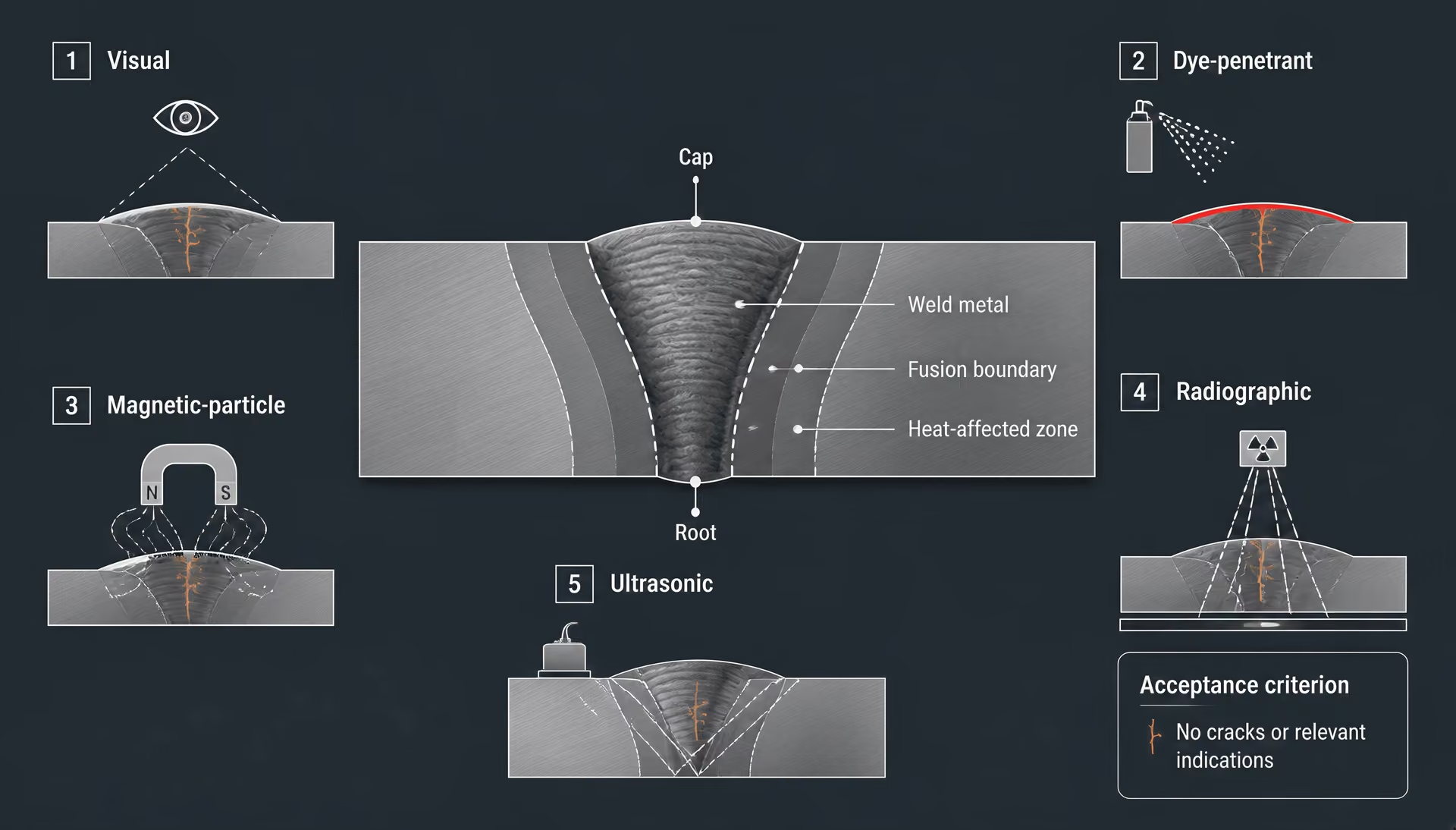
Weld Testing and Structural-Steel Acceptance
A welded assembly is not accepted by applying the parent steel’s mill certificate to the finished connection. The certificate establishes properties of the supplied plate, bar, tube, or shape under the applicable product specification. It does not prove that the deposited weld metal has the required chemistry, that the heat-affected zone retained adequate performance, or that the welder produced a sound joint under the actual fabrication conditions. Weld acceptance therefore links four separate controls: the qualified welding procedure, the qualified welder, fabrication records and inspection, and the acceptance limits assigned to the weld type and loading condition.
This distinction also separates mechanical testing from nondestructive examination. ASTM A370-26 describes tension, bend, hardness, and impact procedures for steel, stainless steel, and related alloy products, but leaves acceptance to the applicable product specification or purchase contract. ISO 377:2017 governs the identification, location, and preparation of samples and test pieces. ISO 6892-1:2019 addresses tensile testing at room temperature, while ISO 148-1:2016 covers Charpy V-notch and U-notch impact testing. Those standards can establish properties of parent material or qualification specimens; they do not, by themselves, decide whether a completed structural weld is acceptable.
AWS D1.1/D1.1M:2025-AMD1 qualification requirements
When invoked by the contract or project documents, AWS D1.1/D1.1M:2025-AMD1 establishes structural-steel welding qualification, fabrication, inspection, and acceptance requirements. Strong evidence
AWS D1.1/D1.1M:2025-AMD1 is the governing welding code for many structural-steel applications when it is invoked by the contract, project specification, or governing building standard. It establishes requirements for welding-procedure qualification, welder and welding-operator qualification, fabrication, inspection, and weld acceptance. Its requirements must be read with the contract documents because the engineer may designate particular weld categories, examination percentages, supplementary requirements, or more restrictive limits.
The code framework begins with the joint and the welding variables, not with a generic statement that “the weld passed.” A qualified welding procedure specification (WPS) identifies the base-metal group, thickness range, joint details, welding process, filler-metal classification, position, preheat and interpass controls, electrical variables, shielding conditions, and any required postweld treatment. A procedure may be prequalified when it meets the code’s prescribed joint details and essential limits. If it falls outside those provisions, procedure qualification testing is required.
AISC guidance identifies AWS D1.1/D1.1M inspection provisions and weld acceptance criteria as a central reference for structural-steel work. The cited AISC guidance also identifies visual testing, dye-penetrant testing, magnetic-particle testing, radiographic testing, and ultrasonic testing as common nondestructive examination methods. It references the inspection and acceptance provisions assigned to the applicable AWS D1.1/D1.1M edition; project documents should control when clause numbering or supplemental requirements differ between editions.
The qualification requirement is not a demand that every production weld receive every test. It is a system for demonstrating that the selected procedure and personnel can produce the specified weld, followed by inspection at the level required for that weld’s function. A primary moment connection, complete-joint-penetration groove weld, fillet weld, repair weld, and temporary attachment may have different examination requirements. The design drawings and inspection plan determine which provisions apply.
Procedure and welder qualification
Procedure qualification demonstrates that a welding method can produce acceptable weld metal and welded-joint performance within stated variable ranges. A test assembly is welded using the proposed process and consumables, then examined and mechanically tested as required by AWS D1.1/D1.1M:2025-AMD1. Typical qualification evidence may include visual examination, bend tests, tensile tests, macroetch examination, or other tests specified for the joint and process. The test piece must represent the qualified base-metal combination, weld type, thickness range, position, and process variables. A result from a different joint or material range cannot automatically qualify the intended production weld.
The report must identify more than a numerical strength value. It should connect the specimen to the WPS and record the base-metal designations, filler-metal classification, dimensions, welding position, preheat, interpass temperature, current, voltage, travel speed, shielding gas where applicable, and test results. A tensile specimen that meets a specified strength is meaningful only when its extraction location and preparation are correct. ISO 377:2017 addresses sample and test-piece location and preparation for steel products; AWS D1.1/D1.1M controls the additional requirements for welded qualification specimens.
Welder qualification answers a different question: can a particular welder or welding operator deposit sound weld metal using the permitted process, position, joint type, and range of thicknesses? The welder performs a qualification test under specified conditions. The resulting test assembly is examined, commonly by visual inspection and by bend or other code-specified tests. Qualification is limited by the variables recorded in the test and by continuity requirements. A qualified welder is not a substitute for a qualified WPS, and a qualified WPS does not qualify an unqualified person.
Fabrication control continues after qualification. The fabricator must use the specified base metal and filler metal, verify consumable control, fit and align the joint, remove contaminants, apply required preheat, control interpass temperature, manage welding sequence, and document repairs when required. Hydrogen-sensitive steels and thick restrained joints may demand stricter control than a qualification coupon suggests. Hardness testing can help investigate a heat-affected zone or repair, but ISO 6506-1:2014 defines the Brinell method; it does not turn a hardness reading into automatic weld acceptance. ISO 18265:2013 provides hardness conversions and tensile-strength estimates but warns that converted values do not replace results from the proper standard test method.
Weld discontinuities, inspection methods, and acceptance criteria
Visual inspection is the first examination because it can be performed during fit-up, between passes, and after completion. It can identify incorrect weld size, poor profile, overlap, undercut, arc strikes, visible cracks, crater defects, porosity open to the surface, incomplete fusion visible at the edge, excessive reinforcement, and dimensional problems. It also verifies details that volumetric methods may not address, such as weld length, termination, access-hole condition, and surface preparation. Visual inspection is not merely a preliminary formality. AWS D1.1/D1.1M acceptance limits apply to visible discontinuities, and a weld that fails visual requirements should not be released on the strength of a later radiograph or ultrasonic report.
Dye-penetrant examination, also called liquid-penetrant testing, is suited to detecting open-to-surface discontinuities in nonporous materials. A penetrant enters a surface-breaking crack or other opening, excess penetrant is removed, and a developer produces an indication. The method does not reveal a discontinuity sealed below the surface. It is therefore useful for suspected surface cracking, including examinations of nonferromagnetic stainless-steel components where magnetic-particle testing is unsuitable, but it cannot establish complete internal weld quality.
Magnetic-particle examination applies a magnetic field to ferromagnetic steel and uses attracted particles to show surface and near-surface discontinuities. It is sensitive to cracks and other defects whose orientation produces a leakage field, so the examination direction and surface condition matter. It does not replace visual inspection or reveal all deep volumetric defects. Demagnetization, access, coating, and weld geometry can affect the result.
Radiographic testing produces an image from differences in transmitted radiation and can reveal certain volumetric discontinuities, such as slag inclusions, porosity, and some forms of incomplete penetration. The image is influenced by thickness, geometry, source placement, film or digital detector quality, and defect orientation. Radiography may be impractical at crowded connections and requires radiation controls. It is not a universal ranking of weld quality.
Ultrasonic testing sends high-frequency sound into the weld and interprets reflected energy from interfaces or discontinuities. It can locate planar and volumetric indications through substantial thicknesses without ionizing radiation, but interpretation depends on calibration, probe angle, geometry, access, surface condition, and technician qualification. A lack of an ultrasonic indication does not prove that every possible discontinuity is absent.
Acceptance criteria define which indications are rejectable, not merely which indications can be detected. They may limit cracks, incomplete fusion, incomplete penetration, undercut, porosity, slag, weld-size deficiency, and accumulated discontinuity length according to weld category and examination method. The inspector must report the method, extent of examination, equipment or procedure, indication location and size, and disposition. Repairs require controlled removal, rewelding under an applicable WPS, and re-examination.
The result is thus a linked decision: the correct weld category and code, a qualified procedure, a qualified welder, controlled fabrication, the specified examination method, and the acceptance limits assigned to that method. Parent-metal tensile or Charpy results remain important, but they cannot certify an uncontrolled welded connection.
Nondestructive Examination of Steel and Welds
Nondestructive examination (NDE) detects or evaluates discontinuities without removing a representative mechanical specimen from the steel or weld. That distinction matters. A weld can produce acceptable radiographic or ultrasonic results while the parent steel has inadequate yield strength, tensile strength, elongation, hardness, or impact toughness. Conversely, a tensile specimen can meet its specified strength while a weld contains an unacceptable lack of fusion.
NDE therefore does not replace tensile, bend, hardness, or impact testing when the governing specification requires those tests. ASTM A370-26 defines procedures for tension, bend, hardness, and impact testing of steel, stainless steel, and related alloy products, but leaves acceptance to the applicable product specification or purchase contract (ASTM International, 2026). ISO 377:2017 addresses the identification, location, and preparation of samples and test pieces; ISO 6892-1:2019 covers room-temperature tensile testing; ISO 148-1:2016 covers Charpy V-notch and U-notch impact testing; and ISO 6506-1:2014 specifies Brinell hardness testing. These standards concern mechanical test results, not a substitute inspection route for weld discontinuities.
Nondestructive examination methods
- Visual examination
- Examines accessible surfaces and weld dimensions.
- Dye-penetrant examination
- Detects discontinuities open to the surface in nonporous materials.
- Magnetic-particle examination
- Detects surface and near-surface discontinuities in ferromagnetic steel.
- Radiographic examination
- Produces an image from differences in transmitted radiation.
- Ultrasonic examination
- Uses reflected high-frequency sound to assess internal indications.
The choice among NDE methods depends on the discontinuity being sought, its expected orientation and depth, the material and geometry, access, weld category, and the governing acceptance rule. A report that says only “passed NDE” is incomplete. It should identify the examined item, method, procedure, extent, indications, disposition, and acceptance criterion.
Visual examination
Visual examination is the first inspection step because it can cover the entire accessible surface quickly and can identify conditions that would make later examination unreliable. The examiner may look for weld size and profile, undercut, overlap, visible cracks, arc strikes, porosity open to the surface, excessive reinforcement, crater defects, incomplete weld length, distortion, surface damage, and incorrect dimensions. Weld gauges, fillet-weld gauges, straightedges, lighting, mirrors, and magnification may support the examination.
Visual examination can reveal only what is visible or measurable from an accessible surface. It cannot reliably establish the depth of a subsurface lack of fusion, internal porosity, buried crack, or lamination. It also cannot determine tensile strength, fracture toughness, or absorbed impact energy. Surface appearance is evidence, not a complete statement of weld integrity.
Preparation and timing affect the result. Slag, spatter, paint, scale, oil, and oxidation can conceal indications or interfere with measurements. Some requirements call for visual examination during welding, after cleaning, or after a specified cooling period, particularly where delayed cracking is a concern. The inspection record should state the lighting and access conditions when the governing document requires them.
For structural steel welds, the applicable edition of AWS D1.1/D1.1M controls the examination requirements and acceptance criteria when it governs the work. AWS D1.1/D1.1M:2025-AMD1 establishes requirements for structural-steel welding, including qualification, fabrication, inspection methods, and weld acceptance criteria (American Welding Society, 2025). AISC identifies visual examination as a common NDE method and points to AWS D1.1/D1.1M Clause 8 for weld inspection methods and acceptance criteria (American Institute of Steel Construction, 2024).
Surface methods: dye-penetrant and magnetic-particle
Dye-penetrant examination, also called liquid-penetrant examination, finds discontinuities open to the surface. After cleaning, a penetrant enters a crack or other surface-breaking cavity by capillary action. Excess penetrant is removed, and a developer draws penetrant back out to form a visible or fluorescent indication. The method can reveal tight cracks, laps, seams, porosity, and lack of fusion that reaches the surface.
It does not detect a discontinuity sealed beneath an intact surface. A coating, rough scale, weld spatter, grease, or inadequate cleaning can block penetrant entry or create confusing indications. Penetrant examination also gives limited information about depth; indication length and brightness are not direct measurements of crack severity. The method is applicable to many nonporous materials, including austenitic stainless steel, but the surface must accept the penetrant process and cleaning agents.
Magnetic-particle examination is aimed at surface and near-surface discontinuities in ferromagnetic steel. The part is magnetized, and iron particles gather where a discontinuity interrupts the magnetic field, producing a visible or fluorescent indication. It can expose cracks at weld toes, crater cracks, grinding cracks, seams, laps, and shallow lack of fusion. Changing the magnetizing direction helps reveal indications that run transverse to the applied field; one direction alone may miss a favorably oriented defect.
Magnetic-particle examination is not suitable for nonferromagnetic grades such as most austenitic stainless steels. It also has limited depth capability, and the result depends on field strength, particle application, surface condition, geometry, and demagnetization requirements. Paint or scale may reduce sensitivity, while abrupt changes in geometry can produce nonrelevant indications. Neither dye-penetrant nor magnetic-particle examination measures steel chemistry, yield strength, hardness, or impact toughness.
The acceptance decision must come from the governing document, not from a generic statement that an indication was found. AWS D1.1/D1.1M Clause 8 may define which indications are rejectable for a particular weld and examination category, while a pipe, pressure-containing, bridge, or machinery specification may impose different limits. API Specification 5L, for example, addresses steel pipe for pipeline transportation systems and the need to specify manufacturing, testing, inspection, and acceptance requirements (American Petroleum Institute, 2013).
Volumetric methods: radiographic and ultrasonic examination
Radiographic examination produces an image from differences in material thickness and density as X-rays or gamma radiation pass through the weld. It can show volumetric discontinuities such as porosity, slag inclusions, cavities, and some forms of incomplete penetration. The image provides a permanent record when the technique and image quality meet the governing requirements.
Radiography has important limits. A planar crack or lack of fusion that lies nearly parallel to the radiation beam may produce little contrast and can escape detection. Access is normally required on opposing sides of the weld for the source and detector, and radiation controls restrict the examination area. Interpretation also depends on thickness, source-to-object geometry, image quality, and the examiner’s ability to distinguish a relevant indication from geometric or processing artifacts. Radiography is not a direct measurement of tensile properties or fracture toughness.
Ultrasonic examination sends high-frequency sound into the steel and evaluates reflected energy. Pulse-echo methods can locate and size indications by their sound-path distance and response. Properly applied, ultrasonic examination can detect internal planar flaws, lack of fusion, incomplete penetration, cracks, laminations, and some volumetric defects. It can inspect thick sections without ionizing radiation and can often examine from one accessible surface.
Ultrasonic results are affected by grain structure, attenuation, surface roughness, curvature, weld geometry, probe angle, calibration, and flaw orientation. A discontinuity parallel to the sound beam may reflect little energy. Weld anisotropy and coarse-grained material can scatter sound and complicate interpretation. Sizing is an evaluation, not a photograph of the defect, and operator qualification, scanning coverage, reference blocks, and written procedures are central to repeatable results.
Selection should follow the defect risk and the governing document. Visual examination may precede surface or volumetric examination; it cannot replace them where internal quality is specified. Dye-penetrant and magnetic-particle methods address surface-breaking or near-surface conditions. Radiographic and ultrasonic methods address internal volume, with different sensitivity to flaw orientation and geometry. AWS D1.1/D1.1M Clause 8, or another applicable code, specification, drawing, or contract, must link the selected method to its required extent and acceptance criterion. The method identifies an indication; the governing document determines whether the steel or weld is acceptable.
Steel Pipe Testing Under API Specification 5L Guidance
Pipeline transportation systems and product requirements
API Specification 5L applies to steel pipe used in pipeline transportation systems for the conveyance of gas, water, and oil. Its purchasing guidance treats the pipe order as a linked set of technical decisions, not as a request for a generic “tested” steel tube. The purchaser must identify the applicable API Specification 5L edition and define the product designation with enough precision for the manufacturer, inspector, and testing laboratory to work from the same requirements.
That designation can include the pipe manufacturing route, nominal or specified dimensions, grade, Product Specification Level (PSL), delivery condition, and any supplementary requirements. Seamless pipe and welded pipe are not interchangeable merely because both satisfy a dimensional description. The manufacturing process affects weld examination, sampling, heat treatment, test locations, and the records needed to demonstrate conformity. A requirement for API 5L pipe therefore needs to distinguish the product form and the applicable provisions for that form.
| Purchase detail | Why it must be stated |
|---|---|
| API Specification 5L edition | Requirements can change between editions. |
| Pipe manufacturing route | Seamless and welded pipe have different controls. |
| Grade and PSL | The selected product level determines applicable verification provisions. |
| Delivery condition | Heat treatment and supplied condition affect requirements. |
| Testing and inspection | Tensile, impact, hardness, hydrostatic, dimensional, and NDE requirements must be selected. |
| Documentation | Records must identify the pipe, heat, specimen, method, and disposition. |
PSL 1 and PSL 2 also need to be stated rather than assumed. The selected level determines which technical requirements and verification provisions apply under the cited edition. Additional purchaser requirements may address chemical analysis, tensile testing, bend or flattening tests, hardness, Charpy impact testing, hydrostatic testing, nondestructive examination (NDE), dimensional inspection, surface condition, traceability, and documentation. The order should identify which requirements are mandatory and which are not applicable.
The test itself is only one part of that chain. ASTM A370-26, for example, provides procedures for tension, bend, hardness, and impact testing of steel, stainless steel, and related alloy products, but it does not decide whether a particular pipe passes. ASTM International states that acceptance comes from the applicable product specification or purchase contract (ASTM International, 2026). API Specification 5L supplies that product framework for line pipe; the purchasing document determines which permitted options and additional controls have been selected.
Specimen identity matters just as much. ISO 377:2017 covers the identification, location, and preparation of samples and test pieces from tubular products as well as sections, bars, rod, and flat products (International Organization for Standardization, 2017). A tensile result from the wrong orientation, location, or product portion cannot be repaired by attaching a valid-looking numerical value to the report. The pipe heat, lot, wall location, weld position where relevant, and specimen orientation should remain traceable from sampling through certification.
Manufacturing, testing, inspection, and acceptance clauses
API Specification 5L purchasing guidance connects four separate questions: how the pipe is made, how its properties are measured, how the product is inspected, and what disposition follows when a requirement is not met. Those questions should appear as coordinated clauses in the procurement specification and inspection or test plan.
Manufacturing clauses establish the permitted process and controls. They may identify seamless or welded production, forming, welding, heat treatment, pipe-end preparation, and repair restrictions. For welded pipe, the specification should also identify the applicable weld-process and examination provisions rather than treating the weld as an incidental feature. Manufacturing records, heat identification, and nonconformance controls provide the context needed to interpret later test results.
Testing clauses should name the test, the governing method, the specimen requirements, and the reporting obligations. ISO 6892-1:2019 specifies tensile testing of metallic materials at room temperature and the mechanical properties that may be determined (International Organization for Standardization, 2019). It does not, by itself, establish the acceptance limit for a particular API 5L grade and product level. The same separation applies to impact testing: ISO 148-1:2016 specifies Charpy V-notch and U-notch pendulum testing for determining absorbed impact energy, while the product requirement establishes whether impact testing is required, at what condition, and how the result is judged (International Organization for Standardization, 2016).
Hardness requires similar discipline. ISO 6506-1:2014 specifies the Brinell method, including use with fixed-location and portable machines (International Organization for Standardization, 2014). A Brinell result may be a required property, a supplementary check, or part of an investigation, depending on the cited product and purchase requirements. ISO 18265:2013 supplies hardness conversions and tensile-strength estimates for specified metallic materials, but warns that converted values do not replace results from the proper standard test method (International Organization for Standardization, 2013). A converted hardness value should not be presented as a substitute tensile test.
Inspection clauses cover activities that are not mechanical-property tests. They can include visual examination, dimensional checks, hydrostatic testing, verification of marking and traceability, and NDE. AISC identifies visual, dye-penetrant, magnetic-particle, radiographic, and ultrasonic examination as common NDE methods and identifies AWS D1.1/D1.1M Clause 8 as a source of weld inspection methods and acceptance criteria (American Institute of Steel Construction, 2024). AWS D1.1/D1.1M:2025-AMD1 itself addresses structural-steel welding, including procedure and welder qualification, fabrication, inspection methods, and weld acceptance criteria (American Welding Society, 2025). That code is not automatically the acceptance authority for API 5L line pipe. Its relevance must come from an expressly applicable contract or engineering requirement.
Acceptance clauses then state how results are evaluated. They should identify the applicable API 5L provisions, supplementary requirements, retest rules, sampling frequency, permitted repairs, and treatment of nonconforming pipe. “Tested in accordance with API 5L” is incomplete if the document does not say which edition, product level, tests, and disposition provisions govern. A test report can be technically correct and still fail to establish contractual conformity when its specimen, method, or acceptance basis is unidentified.
Purchasing-document clarity and test-plan alignment
The purchasing document should function as the controlling map between the pipe designation and the inspection plan. At minimum, it should state the applicable API Specification 5L edition, pipe type and dimensions, grade, PSL, delivery condition where required, manufacturing route, required tests, inspection extent, NDE method, sampling basis, records, and acceptance or disposition rules. If a purchaser invokes a supplementary requirement, the document should cite that requirement precisely and state whether it applies to all pipe, a defined lot, or selected samples.
The inspection and test plan should repeat those decisions in operational form. It should show the manufacturing stage at which each check occurs, who performs it, whether purchaser or third-party witnessing is required, what document records the result, and which clause supplies the acceptance decision. This prevents a common failure: a laboratory prepares a specimen under one standard, reports a property under another convention, and the purchaser later compares it with a limit that belongs to a different product level or edition.
Traceability should run through the entire plan. Heat and pipe numbers, sample locations, specimen orientation, test equipment, calibration status, operator or laboratory identity, test date, and report revision should be connected. For weld-related examinations, the weld seam or area examined and the NDE procedure should also be identifiable. Retests and rejected material need a defined status; otherwise, a replacement result can obscure the original nonconformance.
The purchaser should also resolve conflicts before production begins. If the contract cites API Specification 5L, ASTM A370-26, ISO 6892-1:2019, and a project-specific requirement, it should state which document controls when terminology, specimen geometry, sampling, or acceptance provisions differ. The applicable edition matters because standards change. A clause copied from an earlier edition can silently alter the required test or acceptance path.
API Specification 5L purchasing guidance is therefore most useful when read as a requirements framework. It does not turn every reported value into a pass or fail. The meaningful result is the one that links the identified pipe to the specified manufacturing route, correctly prepared specimen, named test method, required inspection, and applicable acceptance rule (American Petroleum Institute, 2013).
How Acceptance Criteria Are Written and Applied
A steel test result has meaning only when it is tied to the requirement that governs the product. “Yield strength: 355 MPa” is not, by itself, a pass or fail statement. The reader must know the grade, product form, thickness range, specimen direction, specimen condition, test method, sampling frequency, and rule used to judge the result.
An acceptance clause can therefore be read as a chain of linked requirements:
property → unit → test method → specimen condition → sampling frequency → result rule → allowable deviation
For example, a clause might require a minimum yield strength of 355 MPa, determined by tensile testing at room temperature on a longitudinal specimen taken from each heat. The governing product specification may define the yield-strength method, while ISO 377:2017 controls how the sample and test piece are identified, located, and prepared. ISO 6892-1:2019 specifies tensile testing of metallic materials at room temperature and the mechanical properties that may be determined. The number 355 has no independent acceptance meaning if the specimen was taken from the wrong location or tested by an unapproved procedure.
ASTM A370-26 illustrates the division of responsibility. It provides procedures for tension, bend, hardness, and impact testing of steel, stainless steel, and related alloy products, but leaves acceptance to the applicable product specification or purchase contract (ASTM International, 2026). The test standard answers, “How is the measurement made?” The product specification answers, “What value is required?”
Minimums, maximums, ranges, and categorical requirements
A minimum requirement sets a lower boundary. “Tensile strength, minimum: 510 MPa” means a valid result below 510 MPa does not satisfy that criterion, subject to any rounding rule expressly stated by the governing document. A maximum sets an upper boundary, as in “carbon, maximum: 0.18%” or “Brinell hardness, maximum: 220 HBW.” A range has two limits: a result below the lower limit or above the upper limit is outside the specified condition.
The unit matters. A requirement of 355 MPa is not interchangeable with 355 N/mm² by accident; those units are numerically equivalent, but ksi is not. Nor is a hardness value interchangeable with tensile strength merely because a conversion table supplies an estimate. ISO 18265:2013 gives hardness conversions and tensile-strength estimates for specified metallic materials, including unalloyed and low-alloy steels, but warns that a converted value does not replace a result obtained by the proper standard test method. A Brinell result from ISO 6506-1:2014 cannot normally be substituted for a tensile test when the specification calls for tensile strength.
Some requirements are categorical rather than numerical. A product may have to be identified as ASTM A36, ASTM A516/A516M Grade 70, EN 10025-2 S355JR, or API 5L X65, with the designation written exactly as the governing document requires. The condition may be normalized, quenched and tempered, thermomechanically controlled, or delivered in another stated condition. A material certificate that reports acceptable chemistry but does not establish the required heat-treatment condition is incomplete evidence of conformity.
Impact requirements add another layer. A clause may require a minimum absorbed energy at a specified temperature, with a specified number of Charpy V-notch specimens and a rule for the individual values and their average. ISO 148-1:2016 specifies Charpy V-notch and U-notch pendulum impact testing for determining absorbed impact energy; it does not, by itself, establish the acceptance value for a particular grade or contract. Direction, notch orientation, test temperature, specimen size, and location can all change the result.
The same principle applies to welds. AWS D1.1/D1.1M:2025-AMD1 establishes structural-steel welding requirements, including qualification, fabrication, inspection methods, and weld acceptance criteria. A visual examination, magnetic-particle examination, radiographic examination, or ultrasonic examination is meaningful only when the applicable weld category and acceptance provision are identified. AISC lists those methods among common nondestructive examination methods and identifies AWS D1.1/D1.1M Clause 8 as a source of weld inspection methods and acceptance criteria (American Institute of Steel Construction, 2024).
Individual results, averages, and retests
Acceptance clauses must distinguish between an individual result and a statistical or arithmetic average. If three Charpy specimens produce 42, 39, and 18 J, the average is 33 J. That average could meet a 30 J requirement while the 18 J individual result fails a separate minimum of 21 J. Averaging can hide a local or directional weakness, particularly in impact testing, where scatter is often material to the engineering decision.
A requirement may say “minimum average,” “each specimen minimum,” or both. These phrases are not interchangeable. If the clause states only a minimum average, the individual-result rule must be found elsewhere in the same specification, referenced test standard, or contract. If it states a minimum for every specimen, one low value cannot be rescued by two high values. Rounding must also be controlled. Rounding 354.6 MPa to 355 MPa may produce a different decision from comparing the unrounded value with a 355 MPa limit; the document should determine which practice applies.
Sampling frequency is equally important. “One test per heat” differs from “one test per lot,” “one set per 50 tonnes,” and “one test from each end.” API Specification 5L purchasing guidance stresses the need to specify manufacturing, testing, inspection, and acceptance requirements for steel pipe used in pipeline transportation systems (American Petroleum Institute, 2013). The lot definition determines which material a result represents. A passing result from one heat cannot automatically qualify a different heat, even when both carry the same grade designation.
Retesting is not an automatic right created by an inconvenient result. It is allowed only when the governing specification, purchase contract, or approved disposition procedure permits it and states how it is performed. A retest may be appropriate when a specimen breaks outside the permitted gauge location, a machine malfunction is documented, or preparation clearly deviated from the method. It is not a sound basis for discarding a valid low result simply because a second specimen might pass.
When retesting is permitted, the clause may require additional specimens, a new set from the same location, or testing from another location in the same lot. The result rule may require all additional specimens to pass, a revised average, or a defined combination of original and retest values. Those details control the decision. Testing more specimens until a favorable number appears is data selection, not conformity assessment.
Conformance, nonconformance, and disposition
Conformance means that the identified product satisfies every applicable requirement using the specified evidence. Mechanical properties, chemistry, dimensions, surface condition, heat treatment, marking, and nondestructive examination may all be part of that decision. Passing tensile strength does not cure failed chemistry. Acceptable chemistry does not cure an unacceptable weld indication.
A technical nonconformance is a failure against a product or process requirement: yield strength below the stated minimum, carbon above its maximum, impact energy outside the permitted rule, an incorrect specimen orientation, or a weld indication exceeding the applicable AWS D1.1/D1.1M limit. The material may then be rejected, reprocessed, repaired and retested, downgraded where permitted, or accepted by a formally authorized concession. The disposition must identify the affected heat, lot, weld, or component and record the technical basis.
An administrative gap is different. Missing heat traceability, an unsigned report, an unrecorded test temperature, absent calibration evidence, or failure to record specimen orientation may prevent a conformity decision even when the physical material might meet the property limits. That gap is not proof that the steel failed the property. It is a failure of evidence or control. The responsible organization must recover reliable records, repeat the examination where allowed, or treat the requirement as unverified.
This distinction prevents two opposite errors: calling undocumented material “failed” without a technical result, or calling it “passed” because its chemistry or appearance seems satisfactory. The final status should state what was tested, under which method and condition, against which clause, with what result rule, and how any deviation was resolved. Only then does a test result become an acceptance decision.
Test Reports, Certificates, and Audit-Ready Evidence
A steel test result has evidentiary value only when a reviewer can reconstruct what was tested, how it was tested, and which requirement was applied. A certificate that reports “yield strength: 355 MPa” or “hardness: 180 HBW” without identifying the method, product, specimen, and governing specification does not establish conformity. The number may be technically correct yet still irrelevant to the purchase requirement.
ASTM A370-26 illustrates the distinction. It defines procedures for tension, bend, hardness, and impact testing of steel, stainless steel, and related alloy products, but it does not set one universal pass/fail threshold. Acceptance comes from the applicable product specification or purchase contract (ASTM International, 2026). The report must therefore connect the measured value to both the test procedure and the requirement against which it was judged.
Minimum information in a useful test report
The report should identify the material by grade, standard designation, product form, dimensions, and condition of supply. “Steel plate” is not enough. A usable record might identify ASTM A516/A516M Grade 70 plate, normalized condition, 25 mm nominal thickness, or API Specification 5L line pipe with its specified grade and manufacturing route. Heat treatment, surface condition, coating, weld location, and orientation may also affect interpretation and should be recorded where relevant.
Each result needs the test method and edition, not merely the name of the property. A tensile result should cite, for example, ISO 6892-1:2019 or the applicable procedure in ASTM A370-26, together with the reported yield-strength definition, tensile strength, elongation gauge length, and reduction of area where required. ISO 6892-1:2019 specifies tensile testing of metallic materials at room temperature and the mechanical properties that may be determined (International Organization for Standardization, 2019). The report should state whether yield strength means upper yield strength, lower yield strength, or proof strength at a specified extension.
For impact testing, the record should identify ISO 148-1:2016 or the specified alternative, notch type, specimen dimensions, test temperature, individual absorbed-energy values, and any lateral expansion or fracture observations required by the specification. ISO 148-1:2016 covers Charpy V-notch and U-notch pendulum testing for determining absorbed impact energy (International Organization for Standardization, 2016). An average alone can conceal a low individual value.
Hardness records should state the scale, force, indenter, machine type, test locations, and individual readings. ISO 6506-1:2014 specifies the Brinell method for metallic materials and applies to fixed-location and portable machines (International Organization for Standardization, 2014). A reported “180 hardness” has no clear meaning without HBW, test conditions, and method. A converted tensile strength or hardness value must be marked as converted. ISO 18265:2013 warns that conversions do not replace results from the proper standard test method (International Organization for Standardization, 2013).
The report should also show specimen identification, sampling location, orientation, dimensions, surface preparation, and test conditions. Include the operator or laboratory, test date, equipment identification, calibration status where relevant, and any environmental or machine condition that could affect the result. For welding, identify the weld, joint, procedure qualification record, welder, consumable, examination method, and examination extent. AWS D1.1/D1.1M:2025-AMD1 links structural-steel welding requirements with procedure and welder qualification, fabrication, inspection, and weld acceptance criteria (American Welding Society, 2025).
Linking results to heat, lot, and specimen
Traceability is the chain connecting a reported value to the steel from which the specimen came. The chain commonly begins with the manufacturer, cast or heat number, product lot, delivery document, and piece or coil identification. It then continues through the sampling record, specimen number, test machine, raw data, report, and final disposition. If any link is missing, the result may describe steel of the same grade but not the supplied steel.
ISO 377:2017 addresses identification, location, and preparation of samples and test pieces for mechanical testing of sections, bars, rod, flat products, and tubular products (International Organization for Standardization, 2017). Its significance is practical: sampling location and orientation are part of the test definition. A transverse tensile specimen from plate is not interchangeable with a longitudinal specimen from the same heat. A through-thickness sample, surface sample, weld-metal specimen, and heat-affected-zone specimen answer different questions.
The report should state whether sampling was random, specified by lot, taken from an end, or selected from a particular product location. For plate and strip, record rolling direction and distance from the edge or surface when the specification requires it. For pipe, identify the pipe number, seam or seamless condition, and whether the specimen came from the pipe body, weld, or heat-affected zone. For impact specimens, record notch orientation and position. Specimen labels should remain tied to photographs, machining records, and the original sample or retained material.
A certificate covering a heat may support several pieces only if the applicable specification permits that sampling basis and the lot boundaries are documented. A mill certificate that lists one tensile result for an entire shipment, while omitting the heat number or lot definition, cannot show that every delivered piece belongs to the tested population. API Specification 5L purchasing guidance likewise treats manufacturing, testing, inspection, and acceptance requirements as items that must be specified for steel pipe (American Petroleum Institute, 2013).
Nondestructive examination needs the same discipline. A report should identify the examination method, procedure, surface or weld examined, extent, equipment, calibration checks, indications, evaluation level, and acceptance clause. AISC identifies visual, dye-penetrant, magnetic-particle, radiographic, and ultrasonic examination as common methods and points to AWS D1.1/D1.1M Clause 8 for weld inspection methods and acceptance criteria (American Institute of Steel Construction, 2024). “UT passed” is not a sufficient record.
Reviewing deviations and unresolved data
Auditors should treat omissions and departures as technical issues, not clerical details. The review should compare the report with the purchase order, material specification, drawing, inspection and test plan, and approved deviations. Confirm the required grade, product form, dimensions, test frequency, specimen orientation, method edition, test temperature, acceptance limits, and retest rules.
A deviation should identify the original requirement, the actual condition, the reason, the affected heat or lot, the technical assessment, and the approving authority. Replacing ISO 6892-1:2019 with another tensile procedure, for example, may affect strain rate, extensometer use, or reported yield properties. It requires documented technical acceptance, not an unexplained note that an “equivalent method” was used.
Unresolved data must remain visibly unresolved. Missing specimen orientation, illegible heat numbers, absent calibration evidence, contradictory dimensions, and results reported only as averages should be placed on hold until corrected or formally dispositioned. Do not convert a missing result into an assumed pass. Do not treat a retest as the original result; record the first failure, the permitted retest basis, the new specimen identity, and the final rule applied.
The disposition should state whether the material is accepted, rejected, reworked, downgraded, segregated, or accepted by concession. It should name the person or organization authorizing that decision and identify supporting records. This final link matters: test data show what happened in the laboratory, while disposition shows how the responsible specification or contract treated that evidence.
Common Errors in Steel Test Acceptance
Steel test acceptance fails most often at the link between documents, not at the testing machine. A correctly performed tensile test can still support the wrong decision if the specimen came from the wrong location, the report omits a required property, or the result is compared with a limit from another product specification. Acceptance is a chain: material designation, product form, edition, sampling instruction, test method, reported property, and criterion must agree.
Using the wrong edition or an incomplete designation
A standard number without its edition is not a complete instruction. “ASTM A370” identifies a family of procedures, but ASTM A370-26 is the cited 2026 edition. Differences between editions may affect terminology, specimen dimensions, machine verification, reporting, or referenced procedures. The same problem occurs when a report states “ISO 6892” without identifying ISO 6892-1:2019 and the applicable testing conditions.
Designation details matter just as much. “A572” does not identify the required grade, thickness range, product form, or supplementary requirements; ASTM A572 Grade 50 is materially different as an acceptance reference from another grade in the same specification. A pipe report that says only “API 5L” also leaves unresolved the product grade, delivery condition, manufacturing route, test requirements, and inspection provisions. API Specification 5L purchasing guidance treats manufacturing, testing, inspection, and acceptance requirements as items that must be specified rather than assumed (American Petroleum Institute, 2013).
The first correction is documentary. Record the complete designation exactly as invoked: standard, edition, grade or class, product form, thickness or diameter range, delivery condition, supplementary requirement, and purchase-order revision. Then verify that the laboratory report cites the same edition or an explicitly permitted alternative. An old report cannot be made current merely by copying a newer standard number onto its cover.
Sampling errors can hide behind a correctly cited method. ISO 377:2017 governs the identification, location, and preparation of samples and test pieces for steel sections, bars, rod, flat products, and tubular products (International Organization for Standardization, 2017). A longitudinal specimen from mid-thickness is not automatically equivalent to a transverse specimen cut near a surface. Nor are a product-end sample, a weld coupon, and a production part interchangeable. The report should identify heat, lot, product location, orientation, and specimen dimensions before values are compared.
Confusing a test method with a material specification
A test method explains how to measure a property. It does not, by itself, establish whether the material passes.
ASTM A370-26 defines procedures for tension, bend, hardness, and impact testing of steel, stainless steel, and related alloy products, while leaving acceptance to the applicable product specification or purchase contract (ASTM International, 2026). ISO 6892-1:2019 specifies tensile testing of metallic materials at room temperature and the mechanical properties that may be determined (International Organization for Standardization, 2019). Neither reference alone supplies the minimum yield strength, tensile strength, elongation, or reduction-of-area requirement for every steel grade.
The same distinction applies to impact and hardness testing. ISO 148-1:2016 specifies Charpy V-notch and U-notch pendulum impact testing for determining absorbed impact energy (International Organization for Standardization, 2016). It does not decide whether a particular steel must achieve 27 J at −20 °C, an average of three results, or some other contract value. ISO 6506-1:2014 specifies the Brinell hardness method, including fixed-location and portable machines, but a measured HBW value becomes an acceptance result only when the governing material specification sets a hardness limit or permits hardness as the relevant control (International Organization for Standardization, 2014).
A recurring mistake is accepting a tensile result without checking the product specification. “Yield strength: 355 MPa” is a measurement, not a pass statement. The reviewer must ask which yield definition was used, whether the required property is yield strength or proof strength, whether the value applies to the reported thickness, and whether the specification requires elongation, impact energy, bend performance, or additional tests. A result may satisfy one property while failing another.
A corrective review should therefore place the laboratory method beside the acceptance clause. Confirm specimen orientation and dimensions, gauge length, temperature, strain rate where relevant, property definition, units, and the exact minimum or maximum. If the product specification and purchase contract differ, resolve the conflict through the designated engineering or contractual authority; do not select whichever limit produces acceptance.
Weld requirements must remain separate from parent-metal requirements. AWS D1.1/D1.1M:2025-AMD1 addresses structural-steel welding, including welding-procedure and welder qualification, fabrication, inspection methods, and weld acceptance criteria (American Welding Society, 2025). A weld discontinuity limit cannot be applied to an unwelded plate, and a parent-metal tensile requirement cannot replace a required weld procedure qualification or weld examination. The materials, locations, and failure modes are different.
Replacing direct testing with an unqualified conversion
Hardness conversion is useful for controlled comparison, but it is not direct tensile measurement. ISO 18265:2013 provides conversions among hardness scales and estimates of tensile strength for specified metallic materials, including unalloyed and low-alloy steels, cast steels, and tool steels. It also warns that converted values do not replace results from the proper standard test method (International Organization for Standardization, 2013).
That warning should control acceptance decisions. A Brinell result converted to an estimated tensile strength can be affected by alloy composition, microstructure, heat treatment, section size, surface condition, and the hardness scale itself. A conversion table cannot establish elongation, yield behavior, notch toughness, or weld performance. It also cannot repair a missing tensile specimen.
Conformity review sequence
- 1 Match material designation, grade, product form, heat or lot, thickness, and standard edition to the purchase requirement.
- 2 Confirm sample location, orientation, dimensions, preparation, and traceability.
- 3 Separate the test method from the acceptance clause.
- 4 Check every required property and the correct thickness- or temperature-dependent limit.
- 5 Review retest eligibility and preserve the original result.
- 6 Apply weld criteria only to the identified weld, heat-affected zone, or qualification record.
- 7 Record the final disposition and its technical basis.
The final checklist is simple, but it must be applied in order:
1. Match the material designation, grade, product form, heat or lot, thickness, and standard edition to the purchase requirement. 2. Confirm sample location, orientation, dimensions, preparation, and traceability under the applicable sampling standard. 3. Separate the test method from the acceptance clause; never treat ASTM A370-26, ISO 6892-1:2019, ISO 148-1:2016, or ISO 6506-1:2014 as material specifications by themselves. 4. Check every required property, not only tensile strength, and compare it with the correct thickness- or temperature-dependent limit. 5. Do not compare specimens from different locations as though they were equivalent. 6. Treat hardness conversion as an estimate unless the governing specification expressly permits it; direct testing remains necessary where direct testing is required. 7. Apply weld criteria only to the weld, heat-affected zone, or qualification record identified by the governing welding code. 8. Do not assume visual, dye-penetrant, magnetic-particle, radiographic, or ultrasonic examination proves bulk mechanical properties. AISC identifies these as nondestructive examination methods and points to AWS D1.1/D1.1M Clause 8 for weld inspection methods and acceptance criteria (American Institute of Steel Construction, 2024). NDE can reveal specified discontinuities; it does not establish tensile strength, yield strength, or Charpy energy throughout the steel.
A technically correct numerical result does not establish conformity unless its material identity, specimen, method, and acceptance criterion remain linked. Strong evidence
Acceptance is defensible only when each result is tied to the right material, specimen, method, and criterion. Anything less is a number without a valid decision.
A Practical Decision Sequence for Steel Conformance
Steel conformance is not established by attaching a test report to a material certificate and finding a number above a minimum. The result is meaningful only when four things agree: the identified steel, the product form, the specimen and test procedure, and the acceptance clause that governs the order. A tensile result for a plate cannot automatically demonstrate compliance for a pipe, and a hardness conversion cannot replace the tensile test required by the specification.
The practical sequence begins with the material identity and ends with a documented conformity decision.
Identify the governing document
First identify the grade and product form exactly as supplied. Record the designation, heat or cast number, dimensions, delivery condition, and manufacturing route where the governing document requires them. “Austenitic stainless steel” is not sufficient identification; the record should state a designation such as ASTM A240 Type 304 plate, ASTM A106 Grade B pipe, or ASTM A572 Grade 50 structural plate. The same nominal grade may have different requirements when supplied as plate, bar, tube, forging, or welded pipe.
Next establish the controlling document hierarchy. The product specification normally sets chemical, mechanical, dimensional, and inspection requirements, but the purchase order, project specification, drawing, governing construction code, or approved deviation may add conditions. API Specification 5L, for example, addresses steel pipe for pipeline transportation systems and expects purchasing documents to identify applicable manufacturing, testing, inspection, and acceptance requirements (American Petroleum Institute, 2013). For structural weldments, AWS D1.1/D1.1M:2025-AMD1 covers welding procedure and welder qualification, fabrication, inspection methods, and weld acceptance criteria (American Welding Society, 2025).
Do not treat ASTM A370-26 as the acceptance specification merely because it appears on a report. ASTM A370-26 establishes procedures for tension, bend, hardness, and impact testing of steel, stainless steel, and related alloy products. It leaves acceptance to the applicable product specification or purchase contract (ASTM International, 2026). Thus, “tested to ASTM A370” identifies a procedure framework; it does not by itself establish that a plate, bar, or pipe conforms.
The governing document must also identify the required properties. A specification may require yield strength, tensile strength, elongation, reduction of area, bend performance, Charpy absorbed energy, hardness, or a combination of these. A result not requested by the governing document may provide useful information, but it cannot substitute for a missing required result.
Verify sampling and method compliance
Once the requirement is known, check how the sample was taken. ISO 377:2017 specifies identification, location, and preparation of samples and test pieces for mechanical testing of steel sections, bars, rod, flat products, and tubular products (International Organization for Standardization, 2017). This matters because orientation, distance from a surface, product thickness, weld location, and heat identification can affect the reported property. A correctly performed test on the wrong piece is still the wrong evidence.
The report should link each specimen to the heat, lot, plate, pipe, or weld it represents. Confirm the sampling frequency and location against the product specification rather than assuming that one specimen represents every item in a shipment. For welded construction, determine whether the test concerns base metal, weld metal, or the heat-affected zone. Nondestructive examination is a separate matter: visual, dye-penetrant, magnetic-particle, radiographic, and ultrasonic examination locate or assess discontinuities, while tensile and impact tests measure mechanical behavior. A visual inspection result cannot replace a required tensile result.
Then verify the actual test method and its edition. ISO 6892-1:2019 specifies tensile testing of metallic materials at room temperature and the mechanical properties that may be determined (International Organization for Standardization, 2019). The report should show specimen type, dimensions or gauge length, orientation, temperature, and relevant machine or control conditions. These details affect whether elongation, yield strength, and tensile strength are comparable with the limits in the product specification.
For impact testing, ISO 148-1:2016 specifies Charpy V-notch and U-notch pendulum testing for determining absorbed impact energy (International Organization for Standardization, 2016). Notch type, specimen dimensions, test temperature, and individual readings must be checked. A room-temperature Charpy value cannot be compared with a requirement stated at −20 °C.
Hardness requires the same discipline. ISO 6506-1:2014 specifies the Brinell method for metallic materials, including fixed-location and portable machines (International Organization for Standardization, 2014). Check indenter type, force, dwell time, surface condition, and test location. ISO 18265:2013 provides hardness conversions and tensile-strength estimates for specified metallic materials, but warns that converted values do not replace results from the proper standard test method (International Organization for Standardization, 2013). A converted Brinell value therefore cannot satisfy a tensile-strength requirement unless the governing document expressly permits that route.
Compare results with the correct acceptance clause
Compare each required individual result with the exact acceptance clause, not with a general table found elsewhere. The clause may specify minimum yield and tensile strengths, a minimum elongation tied to gauge length, a maximum hardness, a minimum average impact energy, a minimum individual impact value, or permitted dimensional and discontinuity limits. Units and temperature are part of the comparison. So are rounding rules.
Review the actual readings before accepting an average. If a Charpy requirement states both an average and an individual minimum, three values may pass the average while one fails the individual limit. If elongation is reported using a gauge length different from that required by the specification, the numerical value is not directly comparable. The same caution applies to yield strength when the report does not state whether the result is based on a yield point or a specified proof-strength method.
Retesting is not an automatic remedy for any failed value. The governing product specification may permit additional specimens when a test is invalid, a specimen breaks outside the permitted location, or a defined retest rule applies. It may require testing from the same heat or lot, and it may state how replacement results are evaluated. A laboratory cannot erase the first result simply by producing a more favorable second result. The original result, reason for retest, authorization, replacement specimens, and final rule applied must remain in the record.
For welds, compare indications with the applicable acceptance table and examination method. AISC identifies common NDE methods and points to AWS D1.1/D1.1M Clause 8 for weld inspection methods and acceptance criteria (American Institute of Steel Construction, 2024). The governing clause may distinguish between crack-like indications, lack of fusion, porosity, undercut, and size or location limits. “Ultrasonically tested” is not a conformity decision until the indication is assessed under the specified acceptance criteria.
The disciplined workflow is therefore: identify the grade and product form; establish the governing specification, code, or contract; confirm sampling under ISO 377:2017 or the specified procedure; select the required ASTM or ISO method; verify specimen identity, orientation, dimensions, and test conditions; review individual results and supporting documentation; and determine conformity, retest eligibility, or nonconformance under the governing rules. That sequence prevents a valid number from being used as invalid evidence.
References
- [1] ASTM A370-26. ASTM standard, 2026. https://store.astm.org/standards/a370
- [2] ISO 377:2017. ISO standard, 2017. https://www.iso.org/standard/72529.html
- [3] ISO 18265:2013. ISO standard, 2013. https://www.iso.org/standard/53810.html
- [4] Nondestructive examination methods. AISC Engineering FAQs, 2024. https://www.aisc.org/aisc/solutions-center/engineering-faqs/91-non-destructructive-examination-nde-methods/
- [5] AWS D1.1/D1.1M:2025-AMD1. AWS structural welding code, 2025. https://cm.aws.org/standards-and-publications/codes-and-standards/d1-1/
- [6] API Specification 5L purchasing guidance. API purchasing guidance, 2013. https://www.api.org/~/media/files/certification/monogram-apiqr/program-updates/5l%20e45%20purch%20guidelines%20r0%202013%2006%2005.pdf
- [7] ISO 6892-1:2019. ISO standard, 2019. https://www.iso.org/standard/78322.html
- [8] ISO 6506-1:2014. ISO standard, 2014. https://www.iso.org/standard/59671.html
- [9] ISO 148-1:2016. ISO standard, 2016. https://www.iso.org/standard/63802.html