



What Tool Steel Is—and What It Is Not
Tool steel is defined by what it must do in service, not by one chemical recipe or a position on a universal quality ladder. ASM International describes tool steels as “steels used to make tools for cutting, forming, or shaping manufactured parts” (ASM International, 2024). That definition includes cutting tools, punches, dies, molds, forming tools, fixtures, gauges, and other tooling whose working surfaces must retain a controlled geometry while subjected to contact, pressure, friction, impact, or heat.
| Family | Traditional designation | Representative grade |
|---|---|---|
| W | Water-hardening | W1 |
| L | Low-alloy | L6 |
| S | Shock-resisting | S7 |
| O | Oil-hardening | O1 |
| A | Air-hardening | A2 |
| D | High-carbon, high-chromium | D2 |
| H | Hot-work | H13 |
| M | Molybdenum high-speed | M2 |
| T | Tungsten high-speed | T1 |
The word tool therefore describes a function. A steel becomes tool steel in the context of a demanding tooling duty, even though some grades overlap chemically or metallurgically with steels used elsewhere. AISI families commonly identified as W, L, S, O, A, D, H, M, and T cover water-hardening, low-alloy, shock-resisting, oil-hardening, air-hardening, high-carbon high-chromium, hot-work, molybdenum high-speed, and tungsten high-speed steels, respectively. ASM International lists these nine series in its 2020 treatment of tool steels. The letters are not consecutive grades in a performance ranking. They commonly indicate a quenching method, principal application, or dominant alloying system.
No tool-steel family is automatically superior for every application. Strong evidence
That distinction matters when comparing, for example, AISI O1, AISI A2, AISI D2, and AISI H13. O1 is an oil-hardening cold-work steel; A2 is an air-hardening cold-work steel; D2 contains substantially more chromium and carbon, producing a carbide-rich structure associated with high wear resistance; H13 is a hot-work steel designed to retain useful hardness and toughness during thermal cycling. None is automatically superior. A punch that chips under impact may need a different balance from a blanking die that wears through abrasive sheet, even when both are called cold-work tools.
ASM's functional definition
Common tool-steel failure modes
- Abrasive wear Hard particles or asperities remove material from the working surface.
- Adhesive wear Local junctions form between tool and workpiece and tear away material during sliding.
- Plastic deformation The working edge or cavity loses shape under excessive stress or temperature.
- Chipping Small fragments detach from an edge, corner, punch nose, or die land.
- Thermal fatigue Repeated heating and cooling produces surface cracks known as heat checking.
General-purpose engineering steels are usually selected around structural strength, ductility, weldability, corrosion resistance, fatigue performance, or fabrication cost. A structural steel component may be required to carry a load without yielding. A tool must often carry that load while also preserving a sharp edge, cavity, cutting clearance, profile, or calibrated dimension. It can fail by abrasive wear, adhesive wear, plastic deformation, gross fracture, edge chipping, thermal fatigue, corrosion, or loss of dimensional accuracy.
Those failure modes impose competing requirements. Increasing hardness often improves resistance to indentation and abrasive wear, but excessive hardness can reduce resistance to impact or crack propagation. Carbides such as chromium carbide, vanadium carbide, molybdenum carbide, and tungsten carbide can increase wear resistance, yet large, clustered, or poorly distributed carbides may act as crack-initiation sites. Alloying elements also change hardenability, phase transformation, tempering response, hot hardness, and dimensional change during heat treatment. Carbon supports martensitic hardness and carbide formation; chromium, molybdenum, tungsten, and vanadium modify carbide populations and high-temperature behavior; nickel and manganese can affect hardenability and toughness.
Material class A controlled composition and product category that does not specify every microstructural or processing feature governing tool life.
Manufacturing route adds another variable. Forging, rolling, powder metallurgy, remelting practice, and subsequent machining influence segregation, carbide size, carbide alignment, porosity, inclusions, and residual stress. Two pieces carrying the same designation can therefore respond differently if their cleanliness, microstructure, product size, or processing history differs. A designation identifies a controlled material class, not every feature that governs tool life.
Heat treatment then determines how much of that potential becomes usable performance. Austenitizing temperature, soak time, quenching rate, cryogenic treatment where specified, tempering temperature, and the number of tempering cycles affect retained austenite, martensite, carbide precipitation, hardness, toughness, and dimensional stability. A 2020 study reported in Coatings identified heat-treatment parameters as the primary factor controlling tool-core performance in the coated system examined. Its finding does not make composition or manufacturing secondary in every design; those establish the available microstructural range and the defect population that heat treatment must manage.
The practical implication is direct: grade selection begins with the dominant failure mode. A hand-operated cutting tool may favor edge retention and reasonable toughness. A cold-heading tool may need resistance to compressive deformation and chipping. A tap or reamer requires a combination of hardness, cutting-edge stability, machinability, and dimensional control. Embossing tools, dies, punches, cutlery, forming tools, and high-temperature tooling each impose different combinations of load, sliding, impact, and temperature. NBS Monograph 88 remains a useful federal technical reference for the historical terminology and basic metallurgy behind these distinctions.
Tool steel versus general-purpose engineering steel
Tool steel is not simply “stronger steel,” and hardness alone does not define it. A general-purpose alloy steel may provide adequate strength for a shaft, gear, or fastener but fail rapidly when used as a cutting edge or die surface. Conversely, a highly wear-resistant tool steel may fracture when a shock-resisting grade or a tougher engineering steel would survive. Manufacturability also belongs in the calculation: a material that is difficult to saw, grind, machine, wire-cut, weld, or heat-treat may impose failure risks and process burdens before it reaches service.
Routledge’s Tool Steels: Properties and Performance (2021) treats grade behavior through composition, manufacturing processes, heat treatment, surface hardening, and coatings. That framework is more accurate than treating an AISI letter as a simple ranking. Uddeholm’s 2024 cold-work guidance expresses the application principle as selecting a steel that matches the duty while minimizing cost per produced part. Here, that means lifecycle performance: the relevant measure includes tool changes, sharpening, downtime, rejected parts, and premature fracture, not merely the initial material specification.
The role of wrought product forms under ASTM A681
ASTM A681 supplies a standards framework for wrought alloy tool-steel products. ASTM International states in its 2024 scope that “ASTM A681 covers the chemical, mechanical, and physical requirements for wrought alloy tool-steel products.” The covered forms include bars, plate, sheet, strip, rod, wire, and forgings normally fabricated into tools, dies, or fixtures.
That scope is important but limited. ASTM A681 establishes requirements for the supplied wrought product; it does not, by itself, select AISI D2 over AISI A2, prescribe a punch design, or identify whether wear, chipping, heat checking, or distortion is the governing failure mode. The user still must specify the grade, product form, size, condition, heat treatment, surface finish, and acceptance requirements appropriate to the service.
A bar, plate, or forging designation also does not erase directional microstructure or section-size effects. Carbide orientation, segregation, inclusions, and cooling rate can influence grinding response, toughness, and crack growth. The finished tool may require stress relieving, rough machining before hardening, controlled heat treatment, and final grinding to hold its intended geometry. ASTM A681 defines the material framework; engineering judgment connects that framework to the tool’s actual work.
How AISI Tool-Steel Designations Are Organized
Tool-steel designations are classification labels, not a ladder from inferior to superior grades. ASM International defines tool steels as steels used to make tools for cutting, forming, or shaping manufactured parts. Within that broad purpose, the AISI system groups steels according to the feature that originally distinguished their behavior: quenching method, principal application, or dominant alloying system. ASM’s Tool Steels identifies nine principal families: W, L, S, O, A, D, H, M, and T (ASM International, 2020).
The letter therefore gives a starting hypothesis. It does not predict service life by itself. Carbon content, alloy carbides, cleanliness, segregation, powder or ingot route, forging, heat treatment, surface condition, and the tool’s actual failure mode all affect the result. A punch that fractures from impact needs a different balance from a die that wears by abrasion, even when both are cold-work tools. ASTM A681 provides the standards framework for wrought alloy tool-steel products, covering chemical, mechanical, and physical requirements for bars, plate, sheet, strip, rod, wire, and forgings normally fabricated into tools, dies, or fixtures (ASTM International, 2024).
W, L, and S series
The W series means water-hardening tool steel. The designation reflects the traditional quenching medium, not a claim that every W grade must be quenched in water under every modern heat-treatment procedure. These steels are generally carbon tool steels, with limited alloy additions compared with many later tool-steel families. A representative designation is W1. Its relatively simple chemistry can provide a hard martensitic working surface after suitable treatment, while the same limited hardenability restricts the depth and uniformity of hardening in larger sections.
That tradeoff explains the historical use of W steels for hand-operated cutting tools, simple punches, chisels, knives, and similar tools where small sections could cool rapidly. Water quenching also creates substantial thermal stress and distortion risk. The family label describes the intended hardening practice; it does not establish toughness, dimensional stability, or wear resistance without reference to section size and processing.
The L series means low-alloy tool steel. Grades in this family use modest additions of elements such as chromium, nickel, molybdenum, or vanadium to improve hardenability, strength, wear behavior, or stability without moving into the chemistry of high-alloy cold-work or high-speed steels. L6 is a familiar designation. Its nickel-bearing chemistry is associated with a toughness-oriented design, but that does not make every L grade suitable for impact service or every application involving a low-alloy steel.
The S series means shock-resisting tool steel. The defining service requirement is resistance to repeated impact, sudden loading, and chipping rather than maximum attainable abrasion resistance. S7 is a representative grade; S1 and S5 belong to the same broad family but do not have identical compositions or heat-treatment responses. Shock resistance depends on carbon level, alloy balance, grain size, retained austenite, tempering, and defect population. A shock-resisting designation is consequently a clue about the intended compromise between hardness and toughness, not a guarantee against breakage.
O, A, and D series
The O series means oil-hardening tool steel. These grades contain enough alloying additions to harden more gently than plain carbon W steels, permitting oil rather than water in the traditional classification. O1 is the commonly cited example. Oil quenching can reduce distortion and quench cracking relative to water, although dimensional change remains a serious concern in precision dies, punches, taps, reamers, and small forming tools. The O label says how the grade was historically expected to be hardened; it does not mean that its wear resistance exceeds that of an A or D grade.
The A series means air-hardening tool steel. Alloy content raises hardenability sufficiently for a tool to harden in air or under a controlled gas quench, reducing the severe thermal shock associated with water or oil. A2 is widely recognized as an air-hardening cold-work grade. Such steels are selected when a combination of wear resistance, toughness, and dimensional stability is needed in dies, punches, embossing tools, or forming tools. Their lower quench severity can reduce distortion, but retained austenite, carbide distribution, grinding damage, and tempering practice still govern the finished tool.
The D series means high-carbon, high-chromium tool steel. D2 is the representative designation. Its carbon and chromium contents support a substantial population of hard chromium-rich carbides, giving the family its association with abrasive wear resistance and cold-work service. Those carbides also affect toughness, machinability, grinding response, and crack sensitivity. Large or poorly distributed carbides can become crack initiation sites; a D designation cannot reveal carbide size or orientation created by the manufacturing route.
D steels therefore appear in long-running cold-work duties such as dies, punches, shear blades, and forming tools, but the correct choice depends on whether wear, edge chipping, gross fracture, galling, or dimensional change ends service first. High carbon and high chromium are compositional facts, not a universal ranking over the lower-alloy O or A families.
H, M, and T series
The H series means hot-work tool steel. These grades are intended for tooling exposed to elevated temperature during operations such as die casting, hot forging, extrusion, and hot forming. The family is subdivided by dominant alloy systems, including chromium hot-work steels, tungsten hot-work steels, and molybdenum hot-work steels. H13 is a chromium hot-work designation frequently used as a reference point; H-series grades must retain strength, resist thermal fatigue, and limit softening during repeated heating and cooling. Those requirements differ from cold-work abrasion resistance, so a harder room-temperature tool is not automatically a better hot-work tool.
The M series means molybdenum high-speed tool steel. M2 is a representative grade. Molybdenum, tungsten, vanadium, chromium, and carbon form a high-alloy system capable of retaining cutting hardness at temperatures generated during machining. The classification reflects the alloying basis of the high-speed family, while the final cutting behavior depends on austenitizing, quenching, multiple tempering, carbide population, edge preparation, and possible coatings.
The T series means tungsten high-speed tool steel. T1 is the classic representative designation. Tungsten-rich high-speed compositions were historically developed for cutting tools that had to maintain hardness under heat; T grades include carbides that influence red hardness, wear, grinding, and toughness. M and T are not opposing quality levels. They are different alloy-design routes within high-speed tool steels, and the appropriate route depends on cutting temperature, interrupted cutting, edge loading, geometry, and heat treatment.
That processing link is decisive. A 2020 study in Coatings identified heat-treatment parameters as the primary factor controlling tool-core performance, while composition and manufacturing route establish the possible carbide structure and defect population. Routledge’s Tool Steels: Properties and Performance likewise treats performance through composition, manufacturing processes, heat treatment, surface hardening, and coatings (Mesquita, 2021). NBS Monograph 88 supplies an earlier federal reference point for steel metallurgy and historical terminology.
Selection should therefore begin with the failure mode and service conditions, then use the AISI letter as a map to candidate chemistries. Uddeholm states the cold-work engineering objective plainly: match the tool steel to the application and minimize cost per produced part. In practical terms, lifecycle performance matters more than the letter alone. AISI classification organizes the options; it does not make the engineering decision.
The Metallurgical Variables Behind Tool-Steel Performance
Tool steels are defined by service, not by hardness alone. ASM International describes them as steels used to make tools for cutting, forming, or shaping manufactured parts. That definition includes very different demands: a punch may need to resist impact and edge collapse, while a cutting tool must retain a sharp edge under friction and heat. ASTM A681, the relevant standards framework for wrought alloy tool-steel products, covers chemical, mechanical, and physical requirements for bars, plate, sheet, strip, rod, wire, and forgings normally fabricated into tools, dies, or fixtures. The designation does not predict performance by itself.
AISI families such as W, L, S, O, A, D, H, M, and T identify broad alloy and processing concepts. The letters commonly indicate quenching method, principal application, or dominant alloying system, as the Metallurgy text from Maricopa Community Colleges explains. W1 is associated with water hardening, O1 with oil hardening, A2 with air hardening, D2 with high-carbon high-chromium chemistry, H13 with hot-work service, M2 with molybdenum high-speed steel, and T1 with tungsten high-speed steel. These labels establish a starting point. The working structure depends on melting practice, forging or powder processing, austenitizing, quenching, tempering, surface condition, and the particular failure mode.
Carbon, alloying elements, and hardenability
| Element | Principal tool-steel effect described |
|---|---|
| Carbon | Martensitic hardness and carbide formation |
| Chromium | Hardenability and chromium-rich carbides |
| Molybdenum | Secondary hardening and temper resistance |
| Tungsten | Alloy carbides and hot hardness |
| Vanadium | Very hard carbides and grain-size control |
| Nickel | Hardenability and toughness in selected compositions |
Carbon supplies the interstitial atoms that strengthen iron and allows austenite to transform into hard martensite during quenching. Higher carbon generally raises the carbon content of martensite and supports greater as-quenched hardness, but the same addition can increase carbide formation, reduce ductility, and make an edge or corner less tolerant of impact. Carbon also changes how much carbon remains in the matrix after alloy carbides form. A nominal carbon percentage therefore does not state the carbon content of the final martensite.
Key metallurgy terms
- Hardness
- Resistance to localized plastic deformation.
- Hardenability
- The depth to which martensite can form under a specified cooling condition.
- Retained austenite
- Austenite that does not transform to martensite during quenching.
- Secondary hardening
- Hardness increase caused by fine alloy-carbide precipitation during tempering.
Hardenability is different from hardness. It describes how deeply a steel can form martensite under a specified cooling condition. Chromium, molybdenum, manganese, and silicon delay diffusional transformations such as pearlite and bainite, allowing sections farther from a quenched surface to harden. Nickel can assist hardenability and toughness, though it is less associated with strong carbide formation in conventional tool steels. Molybdenum also suppresses certain forms of temper embrittlement and contributes to secondary hardening. The result depends on section size, austenite grain size, quench severity, and the steel’s prior condition.
Chromium has several roles. In moderate amounts it improves hardenability and oxidation resistance; at higher contents it combines with carbon to produce chromium-rich carbides, particularly in high-carbon high-chromium grades such as D2. Molybdenum and tungsten form hard alloy carbides and support secondary hardening when fine precipitates emerge during tempering. Their effect on hot hardness is especially important in high-speed steels and hot-work grades. Vanadium forms very hard vanadium carbides, often VC or V-rich MC carbide, which resist abrasive wear and restrict austenite grain growth when their particles remain fine and well distributed.
Other additions alter the processing window. Silicon strengthens ferrite and can affect tempering response. Manganese improves hardenability but may increase sensitivity to retained austenite and segregation when the composition and treatment are poorly controlled. Cobalt does not form a major carbide population in the usual high-speed-steel sense; it raises the temperature at which the matrix softens and supports cutting performance at elevated temperature. Nitrogen, sulfur, and lead may affect machinability or precipitation, but their value depends strongly on grade and cleanliness requirements.
A steel with high hardenability is not automatically tougher or more wear resistant. It may harden through a large die section, yet contain coarse carbides, segregation, or excessive retained austenite. The heat-treatment study published in Coatings by MDPI in 2020 identified heat-treatment parameters as the primary factor controlling tool-core performance. Composition establishes what structures can form; treatment determines which of those structures actually remain.
Carbides and the wear-toughness balance
Carbide A hard compound formed when carbon combines with iron or alloying elements such as chromium, molybdenum, tungsten, or vanadium.

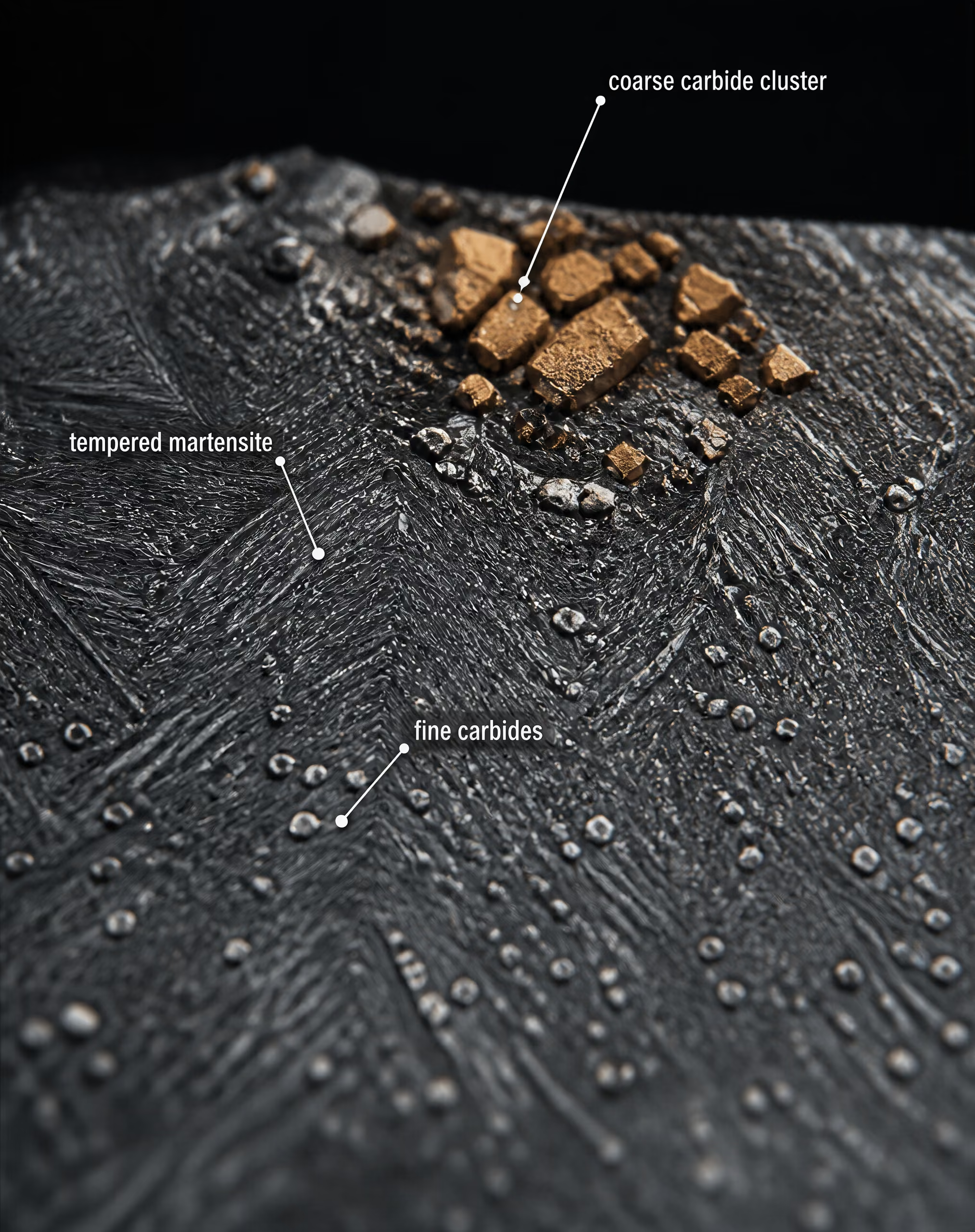
Carbides are central to tool-steel behavior because they are hard particles in a comparatively tougher metallic matrix. Their chemistry, volume fraction, size, shape, spacing, and orientation matter as much as their presence. Iron-rich cementite, chromium-rich M₇C₃, molybdenum- and tungsten-rich M₆C, and vanadium-rich MC carbides do not provide identical resistance to abrasion, thermal softening, or cracking.
A fine, dispersed carbide population can support wear resistance without creating large crack starters. Coarse primary carbides may resist a wear mechanism effectively, but they also interrupt the matrix and concentrate stress. Sharp carbide corners, carbide stringers produced by segregation, and carbide clusters aligned by rolling or forging can become preferred paths for crack initiation. A polished micrograph may show the same nominal carbide type in two grades while revealing very different distributions and therefore very different service lives.
The wear-toughness balance is not a simple exchange between “more carbide” and “less carbide.” Abrasive wear often benefits from a high fraction of hard particles, but edge chipping can accelerate when the matrix between particles is too weak or when carbide spacing is too small to blunt a crack. Adhesive wear, impact wear, plastic deformation, and thermal fatigue impose different requirements. A punch striking a misaligned workpiece may fail by a single unstable chip even though its measured hardness remains high. A shear blade may instead lose performance through gradual abrasive rounding.
| Manufacturing route | Structure or concern described |
|---|---|
| Ingot metallurgy | Chemical segregation and elongated carbide bands |
| Forging and rolling | Grain flow and directional carbide arrangement |
| Powder metallurgy | Finer and more evenly distributed carbide particles |
Manufacturing route changes this structure. Conventional ingot metallurgy can produce chemical segregation and elongated carbide bands that later forging may reduce but not always remove. Powder metallurgy can create a more uniform carbide distribution, although its final properties still depend on consolidation, forging, heat treatment, and surface defects. The point is not that one route always succeeds. It is that nominal chemistry cannot describe the defect population or carbide architecture created by the route.
Tempering adds another layer. During tempering, alloying elements can leave the supersaturated martensite and form fine secondary carbides. In M2 and related high-speed steels, molybdenum, tungsten, and vanadium participate in precipitation that raises hardness after an initial softening stage. This secondary hardening also supports hot hardness, but an aggressive treatment can leave excessive residual stress or retained austenite. Carbide refinement, rather than carbide quantity alone, often determines whether the added alloying content produces useful cutting endurance or brittle edge behavior.
Matrix structure and retained austenite
The matrix surrounding the carbides carries much of the tool’s toughness and supports the carbides under load. Quenched martensite provides high strength because carbon and alloying atoms distort the iron lattice and impede dislocation motion. Untempered martensite, however, contains high residual stress and offers poor resistance to sudden fracture. Tempering reduces that stress, allows controlled carbide precipitation, and adjusts the balance between hardness and toughness.
The austenitizing treatment controls both matrix chemistry and carbide dissolution. If the temperature is too low, insufficient carbon and alloying elements enter austenite, limiting hardenability and final hardness. If it is too high or held too long, excessive carbide dissolution can enrich the matrix, enlarge austenite grains, and increase retained austenite after quenching. Coarse prior-austenite grains reduce the number of barriers available to a propagating crack.
Retained austenite is the portion of austenite that does not transform to martensite during quenching. It can improve apparent toughness immediately after hardening, but it is dimensionally unstable under service stress, grinding heat, or later tempering. Transformation to fresh, untempered martensite may cause distortion, cracking, or changes in cutting geometry. Cryogenic treatment, multiple tempering cycles, or carefully selected austenitizing conditions may reduce this problem, but none is a universal remedy.
The final matrix can contain tempered martensite, retained austenite, secondary carbides, and sometimes bainitic or pearlitic regions caused by inadequate cooling. Their proportions and interfaces govern fatigue, chipping, distortion, and thermal softening. Surface grinding adds another variable: tensile residual stress, grinding burns, and microcracks can defeat a correctly treated core.
Routledge’s Tool Steels: Properties and Performance (2021) treats performance through composition, manufacturing processes, heat treatment, surface hardening, and coatings rather than grade name alone. That approach agrees with the older metallurgical foundations recorded in NBS Monograph 88 and with ASM International’s emphasis on the combined effects of wear resistance, toughness, hot hardness, carbides, and heat treatment. Uddeholm’s cold-work guidance expresses the practical consequence: selection should match the application and reduce lifecycle cost per produced part. The relevant question is not which designation ranks highest, but which matrix-carbide structure can survive the tool’s actual load, temperature, contact, and failure mode.
Manufacturing Route: Why the Same Grade Is Not One Microstructure
A tool-steel designation identifies a composition range and intended family, not a single internal structure. AISI O1, AISI D2, AISI M2, and other grades can therefore show different combinations of toughness, wear resistance, dimensional stability, and machinability when their melting, casting, deformation, and heat-treatment histories differ. ASM International describes tool steels as steels used to make tools for cutting, forming, or shaping manufactured parts; the useful question is not simply which letter appears in the designation, but how the resulting microstructure responds to the tool’s failure mode.
ASTM A681 (2024) covers “the chemical, mechanical, and physical requirements for wrought alloy tool-steel products,” including bars, plate, sheet, strip, rod, wire, and forgings normally fabricated into tools, dies, or fixtures. That standard framework defines product requirements, but it does not make every form of a grade metallurgically identical. Product size, reduction ratio, cooling history, and the location from which a section is taken can all affect the structure delivered to tool manufacture.
Ingot metallurgy and segregation
Conventional wrought tool steel begins with a cast ingot or continuously cast strand. During solidification, alloying elements do not remain distributed perfectly evenly. Carbon, chromium, molybdenum, tungsten, vanadium, and other solutes partition between liquid and solid phases. The last liquid to freeze can become enriched in elements that form carbides, producing chemical segregation between dendrite cores and interdendritic regions. In a high-carbon, high-chromium grade such as AISI D2, that history can influence the size, amount, and distribution of chromium-rich carbides. In AISI M2, tungsten-, molybdenum-, and vanadium-bearing carbide populations likewise reflect both composition and solidification.
Segregation is not the same as a visible defect in every section, but it creates local variation in transformation behavior and carbide formation. Enriched regions may respond differently during austenitizing, and coarse carbide clusters can act as stress concentrators. Under impact or bending, a crack may link through a stringer or cluster rather than through the tempered martensitic matrix. Under sliding or abrasive service, a hard carbide may improve resistance to material removal, while a large, poorly supported carbide can fracture or pull out and damage the working edge.
Nonmetallic inclusions add another layer. Oxide, sulfide, and silicate inclusions can originate in melting, refining, casting, or later processing. Their chemistry, size, shape, and alignment affect fatigue initiation and fracture behavior. The effect is especially important in punches, shear blades, taps, and other tools exposed to repeated loading, where a small internal discontinuity may matter more than a modest difference in bulk hardness.
Forging and rolling reduce cast structure, close internal voids, and redistribute segregated material, but they do not erase the original history completely. The final result depends on temperature, deformation, reduction, and cooling. A large ingot reduced substantially into bar may have a different carbide spacing and segregation pattern from a smaller starting section processed to the same nominal grade.
Forging, rolling, and directional structure
Hot working breaks up cast dendrites and elongates inclusions and carbide-rich regions in the direction of deformation. This produces grain flow and, in many wrought tool steels, a directional carbide arrangement often called banding or carbide alignment. The matrix may become relatively uniform after heat treatment, while elongated carbide strings remain visible in a polished and etched section.
Anisotropy A difference in material response caused by orientation, such as loading along or across carbide stringers or grain flow.
Direction matters because mechanical properties can differ along and across the working direction. A tool loaded parallel to aligned carbide stringers does not experience the same crack path as one loaded transverse to them. Longitudinal toughness, transverse toughness, bending strength, fatigue resistance, and edge stability may therefore diverge even when hardness and chemical analysis are similar. The difference is anisotropy: the material’s response depends on orientation.
The consequence reaches into tool design. A forging die, punch, or blanking component cut from bar should not be treated as directionless stock. The orientation of the tool profile, the dominant service load, and the expected crack path should be considered together. A bar, plate, sheet, strip, rod, wire, or forging also imposes different machining and forming decisions. A thick plate may require removal of a surface layer or attention to through-section variation; strip may be selected for a small formed component whose final direction follows rolling; wire and rod may feed cold-forming or heading operations in which surface condition and axial defects become significant.
Grain flow is useful when it supports the applied load, but harmful when it presents an easy path for splitting or edge failure. Banding can also produce uneven response during heat treatment, especially where local composition changes alter hardenability or retained austenite. A nominally identical AISI O1 tool made from different product forms may consequently need different allowances for machining distortion and may fail by chipping, bending, or cracking for different reasons.
The 2020 ASM International treatment states that tool-steel performance depends on combinations of wear resistance, toughness, hot hardness, carbides, and heat treatment. Routledge’s Tool Steels: Properties and Performance (2021) makes the same broader point by treating composition, manufacturing processes, heat treatment, surface hardening, and coatings as connected variables. Manufacturing route sets the starting condition; it does not replace heat treatment. A 2020 study in MDPI’s Coatings identified heat-treatment parameters as the primary factor controlling tool-core performance, while composition and prior processing establish the material’s potential and defect population.
Powder metallurgy and carbide refinement
Powder-metallurgy tool steel changes the solidification problem rather than merely repeating conventional production on a smaller scale. Molten alloy is atomized into fine particles, each particle freezing rapidly and carrying a comparatively small segregated volume. The powder is then compacted and consolidated, commonly by hot isostatic pressing, followed by thermomechanical processing and heat treatment.
Rapid particle solidification limits the growth of large carbide networks. After consolidation, carbide particles are generally finer and more evenly distributed than in conventionally cast-and-wrought material of the same nominal composition. The reduction in coarse carbide clusters can improve resistance to carbide fracture, edge chipping, and crack propagation, while the more uniform structure reduces property variation with section and orientation. These are structural tendencies, not automatic guarantees; consolidation defects, unsuitable heat treatment, excessive carbide content, and poor surface preparation can still control failure.
The contrast is clearest in high-alloy grades containing substantial carbide-forming elements. Conventional AISI D2 can contain sizeable chromium-rich carbide populations with alignment inherited from working. A powder route can produce a finer distribution of chromium carbides, although the exact phases and sizes depend on atomization, consolidation, forging or rolling, and thermal treatment. Powder versions of high-speed steels such as AISI M2 similarly aim to control carbide spacing and reduce segregation-related anisotropy. The designation still identifies the alloy family. It does not specify one carbide size or one toughness level.
This distinction matters when a tool is made from bar, plate, strip, rod, wire, or a forging. Machining removes material, but it does not remove directional structure throughout the remaining tool. Grinding can expose carbide-rich regions and can introduce tensile residual stress or localized thermal damage at the surface. A process route that gives the core a fine, homogeneous structure may therefore provide a different margin against chipping than a conventional wrought route, even after both materials receive the same nominal hardness treatment.
Uddeholm’s 2024 cold-work guidance expresses the practical engineering rule: tool-steel selection should match the application and minimize cost per produced part. That means matching route and product form to the dominant failure mode—wear, impact fracture, plastic deformation, heat checking, fatigue, or edge chipping—not ranking AISI letters from low to high. The same grade name can describe materially different starting structures, and those structures remain part of the tool long after the steel has been machined.
Heat Treatment Is the Performance-Defining Process
A tool-steel grade does not enter service with the properties implied by its designation alone. AISI D2, for example, identifies a high-carbon, high-chromium cold-work steel family; it does not guarantee a particular combination of hardness, toughness, dimensional stability, or wear life. Those properties emerge after the steel has been heated, held, cooled, and tempered under conditions suited to its chemistry and section size.
Heat-treatment parameters were the primary factor controlling tool-core performance in the coated system examined. Limited evidence
This is the central technical point in the 2020 Coatings study published by MDPI, volume 10, issue 3, article 265. The study identifies heat-treatment parameters as the primary factor controlling the performance of the tool core in the coated system examined. Composition and manufacturing route establish the available microstructural potential and the population of inclusions, segregation, pores, and carbides. Heat treatment determines how much of that potential is realized. A coating cannot compensate for a core that was overheated, underhardened, cracked during quenching, or left with excessive retained austenite.
Heat treatment sequence
- Preheating Reduce the temperature gradient between the furnace and the workpiece.
- Austenitizing Transform the matrix and dissolve a controlled amount of carbide.
- Quenching Cool rapidly enough to form martensite while limiting thermal and transformation stress.
- Tempering Reduce residual stress, adjust hardness and toughness, and stabilize the structure.
The sequence is normally controlled through preheating, austenitizing, quenching, and tempering, but the sequence is not a universal recipe. AISI W, L, S, O, A, D, H, M, and T steels respond differently because their carbon, chromium, molybdenum, tungsten, vanadium, manganese, and silicon contents change transformation temperatures, carbide stability, hardenability, and tempering response. ASTM A681, which covers the chemical, mechanical, and physical requirements for wrought alloy tool-steel products, provides the standards framework; it does not replace the grade-specific heat-treatment schedule.
Austenitizing and dissolution control
Preheating reduces the thermal gradient between the furnace and the workpiece. That matters particularly for large sections, intricate punches, sharp corners, and steels containing substantial carbide populations. A staged preheat may be used where the grade or geometry creates a high risk of thermal stress. The purpose is not simply to save furnace time. It reduces the temperature difference between the surface and core before austenitizing begins.

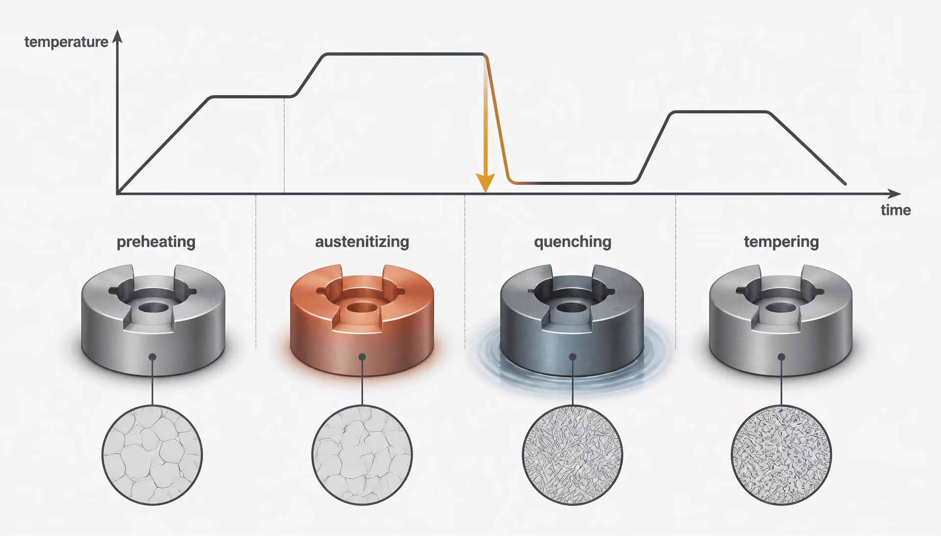
Austenitizing then raises the steel into a temperature range where sufficient ferrite or pearlite transforms to austenite and selected carbides dissolve. Carbon and alloying elements entering austenite control hardenability and the response during tempering. The amount dissolved must be controlled. Too little dissolution leaves excessive undissolved carbide and an austenite matrix that may not harden to the required level. Too much dissolution can produce coarse austenite grains, excessive alloy content in solution, greater retained austenite, and reduced toughness.
The distinction is important in high-carbon high-chromium grades such as AISI D2. Their chromium-rich carbides provide wear resistance, but those carbides are not meant to dissolve completely. The heat treater is controlling a balance between a hard martensitic matrix and a useful, stable carbide structure. AISI M and T high-speed steels require still different control because molybdenum, tungsten, vanadium, and chromium form alloy carbides that support hot hardness and secondary hardening. Their austenitizing temperatures are high, and the permitted process window can be narrow.
Underheating is often mistaken for a toughness-preserving treatment. If the austenitizing temperature or soak is inadequate, the matrix may contain too little dissolved carbon and alloying element, producing low hardness and poor wear resistance after quenching. Overheating creates a different set of failures: grain coarsening, excessive retained austenite, greater distortion, and a higher risk of quench cracking. Long holding times can also intensify decarburization or oxidation at the surface.
Surface condition must be controlled during heating. Decarburization removes carbon from the outer layer, leaving a softer skin that may fail by premature rounding, galling, or plastic deformation even when the interior hardness is correct. Protective atmosphere, vacuum processing, salt baths, suitable furnace practice, and post-treatment grinding are possible controls, but their suitability depends on the grade and the geometry. A hardness reading taken below a decarburized layer can conceal the defect.
Section size changes the required heating and holding practice. A thin punch reaches temperature quickly; a large die may show a substantial surface-to-core lag. Applying a small-part schedule to a heavy section can leave an underaustenitized core, while holding a thin section for the time required by a large block promotes grain growth and surface damage. Heat-treatment instructions therefore specify both temperature and time, often with furnace loading and section thickness assumptions.
Quenching, hardening, and tempering
| Family | Traditional cooling medium | Principal processing concern |
|---|---|---|
| W | Water | Quench cracking and distortion |
| O | Oil | Section hardenability and dimensional change |
| A | Air or controlled gas | Retained austenite and nonuniform cooling |
| D | Air or controlled gas | Carbide structure and dimensional stability |
| H | Air or pressurized gas | Thermal fatigue and hot softening |
Quenching converts the austenitized structure into martensite when cooling is fast enough to avoid excessive formation of pearlite or bainite. The required cooling severity depends on hardenability. Water-hardening AISI W steels need rapid cooling and consequently carry greater risks of distortion and cracking. Oil-hardening AISI O steels permit less severe cooling. Air-hardening AISI A, D, H, and many high-speed grades can harden through larger sections with lower quench stress, although “air hardening” does not mean that every geometry will cool uniformly or reach the same hardness at its center.
Quenching is a mechanical event as well as a metallurgical one. The surface contracts while the interior remains hot; then the core contracts as it cools. Sharp corners, abrupt changes in section, holes, keyways, and poorly supported parts concentrate stress. Quench cracking can follow, especially where the cooling medium is too severe, the steel was overheated, machining marks remain, or the design contains stress raisers. Distortion may occur without a visible crack. A die can bow, a punch can lose concentricity, or a cutting edge can move enough to affect clearance and alignment.
Interrupted quenching, staged cooling, martempering, or press quenching may reduce stress, but each method must be validated for the grade and part. The objective is not the fastest possible cooling. It is sufficient transformation with controlled stress and acceptable dimensional change.
Freshly quenched martensite is hard but brittle and contains high internal stress. Tempering should follow quenching without unnecessary delay. It reheats the steel below the austenite transformation range, allowing carbon to leave supersaturated martensite and form transition carbides or cementite, while reducing residual stress. Insufficient tempering can leave a tool vulnerable to cracking in service, even when a hardness test reports the specified nominal value. A single temper may not adequately stabilize the structure in grades with significant retained austenite; double or triple tempering is often specified for such steels.
Some alloy systems show secondary hardening. In AISI M and T high-speed steels, and in selected high-alloy hot-work and cold-work grades, tempering can precipitate fine alloy carbides such as molybdenum-rich, tungsten-rich, or vanadium-rich carbides. Hardness may rise during a suitable high-temperature temper rather than simply decline. This response depends on the austenitizing treatment, the amount of alloy dissolved, the cooling path, and the tempering schedule. It cannot be assumed for every tool steel, and a higher hardness number does not automatically mean better service.
Nominal hardness is only one measurement. A tool with higher Rockwell hardness may fail sooner than a slightly softer tool if its carbide network is coarse, its edge contains a decarburized layer, its toughness is inadequate, or its retained austenite transforms during operation. Service performance also depends on wear mechanism, impact loading, temperature, lubrication, contact pressure, and the quality of the working surface. ASM International’s 2020 treatment of tool steels therefore links performance to combinations of wear resistance, toughness, hot hardness, carbides, and heat treatment rather than to hardness in isolation.
Dimensional change, retained austenite, and cryogenic treatment
Dimensional change begins during heating and continues through quenching, tempering, and service. Transformation from austenite to martensite involves a volume change, while carbide precipitation and retained-austenite transformation can alter dimensions later. The direction and magnitude vary with grade, geometry, prior cold work, orientation, and processing route. A precision reamer, blanking die, or forming insert may require machining allowance, stress relief, cryogenic stabilization, or finish grinding after heat treatment.
Retained austenite is the portion of austenite that does not transform during quenching. High carbon and alloy content, excessive austenitizing temperature, and insufficient quench severity can increase its amount. It is softer than martensite and can transform later under tempering, cooling, grinding, or service stress. That delayed transformation can cause dimensional drift, cracking, or changes in cutting-edge geometry. In a die, a small dimensional shift may alter clearance; in a reamer, it can change the finished bore.
Cryogenic treatment, usually applied after quenching and before or between tempering operations, can promote further transformation of retained austenite to martensite. It is not a substitute for correct austenitizing, quenching, or tempering. Excessive or poorly timed cooling can increase stress, and the resulting fresh martensite still requires tempering. Its usefulness must therefore be demonstrated for the specific steel, geometry, and failure mode rather than added as a ritual step.
Heat treatment should be judged against the tool’s actual service requirement. Uddeholm’s 2024 cold-work guidance expresses the engineering objective as matching the steel to the application and minimizing cost per produced part; in metallurgical terms, that means controlling the complete lifecycle of the tool rather than selecting a grade by letter or hardness alone. The sequence, atmosphere, thermal uniformity, quench method, tempering response, surface condition, and dimensional tolerance all belong to the specification. Composition makes a performance range possible. Heat treatment decides where within that range the finished tool operates.
The Major Performance Properties and Their Tradeoffs
Tool-steel performance cannot be read from a hardness number or a grade letter alone. ASM International defines tool steels as steels used to make tools for cutting, forming, or shaping manufactured parts, but the service result depends on the interaction among matrix hardness, carbide population, toughness, heat treatment, surface condition, manufacturing defects, and the dominant failure mode. ASTM A681:2024 covers “the chemical, mechanical, and physical requirements for wrought alloy tool-steel products,” including bars, plate, sheet, strip, rod, wire, and forgings normally fabricated into tools, dies, or fixtures. Its requirements describe material; they do not create a universal ranking of W, L, S, O, A, D, H, M, and T grades.
A useful comparison therefore asks a sharper question: is the tool failing by abrasive wear, adhesive wear, plastic deformation, fatigue cracking, impact fracture, thermal cracking, or loss of dimensional accuracy?
Hardness and abrasive or adhesive wear
Hardness is resistance to localized plastic deformation, commonly measured by Rockwell C, Vickers, or similar tests. It is not the same thing as wear resistance. A harder surface usually resists plastic grooving and indentation more effectively, yet abrasive wear also depends on the hardness, size, spacing, and continuity of carbides. A high-carbon high-chromium grade such as AISI D2 may resist abrasive attack through hard chromium carbides, while a lower-alloy shock-resisting grade such as AISI S7 may sacrifice some wear resistance to tolerate impact and stress concentration.
Abrasive wear occurs when hard particles or asperities cut, plow, or microscratch the tool surface. Adhesive wear occurs when local junctions form between tool and workpiece, then tear away material during sliding. Adhesive damage is affected by surface finish, lubrication, contact pressure, temperature, and chemical affinity, not merely by bulk hardness. A polished forming surface can behave differently from a ground surface containing sharp grinding marks, residual tensile stress, or a heat-affected layer.
Carbide morphology is central. Fine, evenly distributed carbides can raise wear resistance without creating as many crack-starting sites as coarse, clustered carbides. Large carbide strings aligned by rolling may produce directional behavior: wear can be acceptable across the string direction but fracture resistance can be poor when a crack follows the elongated population. Powder-metallurgy routes can produce a more uniform carbide distribution than conventional ingot metallurgy, but the resulting response still depends on composition and heat treatment.
Hardness also changes the matrix around those carbides. Excessive austenitizing temperature may dissolve more carbon and alloying elements, increasing hardenability or secondary hardening potential, while also promoting grain coarsening and retained austenite. Insufficient temperature can leave undissolved carbides and a matrix that cannot reach the intended hardness. Tempering then controls the balance among hardness, residual stress, toughness, and temper resistance. A 62 HRC reading says little about whether a punch will survive repeated impact if its carbide network is coarse or its edge contains a grinding crack.
Compressive strength is another separate property. Tool steels often tolerate high compressive stress because a hardened martensitic matrix resists plastic flow, which matters in dies, punches, and cold-heading tooling. However, compressive strength does not prevent tensile cracking at a notch, corner, inclusion, or damaged edge. Contact geometry can convert nominal compression into local shear and tensile stress. The correct comparison is therefore hardness plus wear mechanism plus stress state.
Toughness, fatigue, and fracture resistance
Toughness is the capacity to absorb energy before cracking or fracturing. Impact toughness, often assessed with Charpy testing, is especially relevant to punches, shear blades, dies exposed to interrupted loading, and hand-operated cutting tools. A high hardness value can coexist with low impact toughness because the same carbon content, martensitic structure, carbide clusters, and residual stresses that raise resistance to indentation can reduce the energy needed to extend a crack.
Fracture resistance is more specific than impact toughness. It describes resistance to crack growth under a defined geometry and loading condition, often expressed through a stress-intensity or fracture-toughness measurement. Neither property is a fixed grade attribute. Section size changes cooling rate during quenching, and cooling rate changes martensite formation, carbide precipitation, retained austenite, and internal stress. A small coupon may show the target hardness while the center of a large die contains softer transformation products or quench-related defects.
Fatigue adds repeated loading. Bending fatigue is governed by the cyclic stress range, mean stress, surface finish, residual stress, and local geometry. A polished radius may endure many more cycles than a sharp corner with the same nominal stress, because the corner raises the local stress concentration. Tool marks, decarburization, grinding burns, laps, seams, and nonmetallic inclusions can act as initiation sites. Failure may occur below the single-load strength because thousands or millions of cycles progressively extend a small crack.
This explains why a grade selected for wear can fail earlier than a tougher grade in a punching operation. The failure may not be abrasive loss at all; it may be edge chipping from impact, fatigue at the fillet, or cleavage through a carbide stringer. Tempering reduces quench stress and can improve fracture resistance, but tempering at an unsuitable temperature may lower hardness or produce embrittlement. Multiple tempering cycles are used for some high-alloy grades to transform retained austenite and stabilize dimensions.
Surface condition deserves equal weight with nominal chemistry. A sharp edge improves cutting action but raises local stress. A rough surface increases friction and adhesive damage, while an over-ground surface may contain tensile residual stress. Nitriding, coatings, and other surface treatments can reduce friction or increase surface hardness, yet a hard, poorly supported layer can crack or spall if the substrate lacks toughness. Routledge’s Tool Steels: Properties and Performance (2021) treats composition, manufacturing process, heat treatment, surface hardening, and coatings as linked parts of grade behavior rather than independent labels.
Hot hardness, thermal fatigue, and dimensional stability
Hot hardness The ability of a steel to retain useful hardness and resistance to plastic deformation at elevated temperature.
Hot hardness is the ability to retain useful hardness and resistance to plastic deformation at elevated temperature. It matters in high-speed cutting, hot forging, extrusion, and dies that receive repeated contact with hot stock. A tool may remain hard at room temperature yet soften during service if its tempering resistance is inadequate. Molybdenum high-speed grades in the M series and tungsten high-speed grades in the T series develop secondary hardening from alloy carbide precipitation; the exact response depends on austenitizing, quenching, and tempering schedules.
Heat checking A network of surface cracks produced by repeated heating and cooling, especially in hot-work tooling.
Thermal fatigue is different from simple softening. Repeated heating and cooling produce cyclic expansion and contraction. Surface layers heat first, while the core remains cooler, creating thermal gradients and alternating stresses. Cracks commonly initiate at corners, machining marks, carbide clusters, or other stress raisers and then form networks often called heat checking. Hot-work grades in the H family are designed around this problem, but no designation eliminates it. Cooling method, die geometry, contact time, lubrication, and temperature variation remain decisive.
Dimensional stability means retaining shape and size through hardening and service. Quench distortion results from uneven heat transfer and unequal transformation strains; retained austenite can later transform and expand; decarburization can produce a soft surface that wears or deforms even when the interior meets specification. Large sections are particularly difficult because the surface and core experience different thermal histories. Vacuum processing, controlled atmospheres, suitable fixturing, staged quenching, and correct tempering can reduce these effects, but they cannot compensate for an unsuitable section design.
The 2020 MDPI Coatings study identified heat-treatment parameters as the primary factor controlling tool-core performance, while composition and manufacturing route establish the available potential and defect population. That finding supports a practical rule: compare tested, heat-treated material in a geometry and condition resembling service. AISI O1, A2, D2, S7, H13, M2, and T1 are not points on a simple ladder. Their value depends on whether the tool needs edge retention, impact survival, compressive support, resistance to thermal cycling, or dimensional control.
Uddeholm’s 2024 cold-work guidance expresses the same engineering principle through lifecycle performance: select a steel that matches the application and minimize cost per produced part. The meaningful measure is not maximum hardness. It is the number of sound parts produced before wear, chipping, fatigue, fracture, heat checking, or distortion requires intervention.
Water-Hardening, Low-Alloy, and Shock-Resisting Tool Steels
The W, L, and S designations describe different compromises rather than a ladder from inferior to superior steel. AISI uses the letters W, L, S, O, A, D, H, M, and T for major tool-steel families, and the letters commonly identify a quenching method, principal application, or dominant alloying system. That classification is useful, but it does not predict tool life by itself. Carbon content, alloy carbides, section size, machining marks, heat-treatment practice, surface condition, and the actual failure mode all affect the result.
ASTM A681 provides the standards framework for wrought alloy tool-steel products, including bars, plate, sheet, strip, rod, wire, and forgings normally made into tools, dies, or fixtures. Its chemical, mechanical, and physical requirements establish what a grade must meet; they do not remove the need to select a grade for a particular geometry and load.
W series and water quenching
The AISI W series is the water-hardening group. These steels depend mainly on carbon for martensite formation and contain relatively limited alloy additions compared with air-hardening or high-speed grades. Common designations include W1 and W2. Their composition permits a high surface hardness after austenitizing and water quenching, making them suitable for hand-operated cutting tools, small punches, scribers, knives, simple dies, and other tools in which a hard working edge matters more than deep hardening.
The same feature creates the central limitation. A plain-carbon or lightly alloyed section loses heat quickly and must cool rapidly enough to transform austenite into martensite. Water provides severe cooling, particularly near the surface. The interior of a thick tool may cool more slowly, leaving a hardness gradient or a mixture of transformation products. A narrow blade can harden effectively; a thick punch may not.
Water quenching also raises distortion and cracking risk. The surface contracts while the core is still hot, and the resulting thermal and transformation stresses are sensitive to sharp corners, abrupt changes in section, keyways, holes, and grinding damage. A tool can leave the furnace with the required nominal grade and still fail because its geometry concentrated stress during quenching. Preheating, controlled austenitizing, suitable quench agitation, immediate tempering, and generous fillets reduce that risk, but they cannot make water-hardening steel behave like a deep-hardening alloy.
W grades therefore suit relatively simple sections and applications where the operator can accept a narrow hardening zone or where the tool is small enough to cool through. A hand chisel, for example, needs a hard cutting end but also needs a tempered, less brittle body. Excessive hardness throughout the tool may improve resistance to edge wear while making the shank prone to fracture. The correct result is a heat-treatment condition, not merely a grade label.
Carbon also controls the balance between hardness and toughness. Increasing carbon can raise attainable hardness, but untempered high-carbon martensite has little tolerance for impact or tensile stress. W-series performance is consequently strongly dependent on tempering temperature, holding time, and section size. Grinding after hardening introduces another risk: a burned or tensile-stressed surface can initiate cracking even when the bulk structure is acceptable.
L series and low-alloy hardening
The AISI L series identifies low-alloy tool steels. The additions are modest compared with those in high-chromium cold-work, hot-work, or high-speed grades, yet small amounts of nickel, chromium, molybdenum, manganese, or other elements can materially change hardenability and toughness. L2 and L6 are familiar designations, but they do not represent identical behavior. L6, for instance, is associated with a nickel-containing low-alloy composition and is selected where greater toughness and hardenability are needed than a plain water-hardening grade commonly provides.
Low alloying allows the steel to harden more deeply and can permit a less severe quench than water, depending on the grade, section, and prescribed treatment. That may reduce distortion and quench cracking in a large punch, forming tool, or fixture. It does not guarantee dimensional stability. A long slender tool can still bow, a thin edge can still move, and retained austenite or uneven furnace conditions can still produce dimensional change.
The application-specific nature of L steels is especially important. A tool for cold forming may require a hard working surface and a tough core; a gauge or fixture may instead place greater emphasis on dimensional stability; a large cutting or forming component may need through-hardening without the severe thermal shock of water. The same nominal hardness can conceal different microstructures, carbide distributions, and residual stresses. Heat treatment must therefore be matched to the particular L grade, not copied from a W-series procedure.
Manufacturing route matters as well. Forging, rolling, annealing, and machining establish grain flow, segregation, inclusions, and residual stress before hardening. Routledge’s Tool Steels: Properties and Performance presents performance through the combined effects of composition, manufacturing processes, heat treatment, surface hardening, and coatings. This is a more accurate model than treating “low alloy” as a direct measure of strength.[1] The effect of heat treatment on tool-core performance in a coated system. Authors not specified in the article. Coatings, 2020.
A 2020 study published in MDPI Coatings identified heat-treatment parameters as the primary factor controlling tool-core performance in the coated system it examined. The finding has wider practical significance: a coating cannot correct a soft, brittle, overheated, or poorly tempered substrate. Surface engineering changes surface behavior; it does not replace sound core metallurgy.
S series and impact-dominated service
The AISI S series is the shock-resisting family. These grades are intended for repeated impact, intermittent loading, or sudden changes in contact stress, where fracture resistance is more important than the maximum attainable wear resistance. S1, S5, and S7 are established designations, with differences in alloying and heat-treatment response that make them behave differently under service.
A chisel, rivet header, shear blade subject to interrupted work, pneumatic tool, or punch that experiences impact may need the S-family balance of hardness and toughness. The required structure usually contains tempered martensite with controlled carbide content rather than a heavily carbide-loaded matrix designed primarily for abrasive wear. More carbide is not automatically better: coarse or poorly distributed carbides can act as crack-initiation sites when the tool is struck.
S steels still require a deliberate hardness choice. If tempered too soft, a punch may mushroom, a chisel may roll, or a forming edge may deform. If hardened and tempered too hard, the same tool may chip or break. Geometry can dominate the outcome. A sharp notch, thin unsupported edge, or abrupt shoulder raises local stress, while a generous radius and suitable land distribute the impact. Even a tough grade can fail when the design forces tensile stress across a brittle edge.
The S designation therefore signals service emphasis, not immunity to abuse. Impact resistance depends on cleanliness, grain size, carbide distribution, austenitizing control, quench severity, tempering, and surface finish. NBS Monograph 88 remains useful for the historical language of steel metallurgy, while ASM International connects tool-steel performance with wear resistance, toughness, hot hardness, carbides, and heat treatment. Uddeholm expresses the resulting engineering principle in lifecycle terms: cold-work tooling should be matched to its application to minimize cost per produced part. For W, L, and S steels alike, that means identifying whether failure comes from wear, plastic deformation, cracking, chipping, or dimensional change before selecting the family.
Oil-Hardening, Air-Hardening, and High-Carbon High-Chromium Grades
The O, A, and D families are often presented as a progression from ordinary to advanced tool steel. That interpretation is wrong. Their letters describe different metallurgical priorities: O indicates oil hardening, A indicates air hardening, and D identifies high-carbon high-chromium steel. None is a universal ranking. A punch that survives repeated impact may fail when made from a wear-focused D grade, while an A-series die may resist distortion yet perform poorly when edge chipping controls tool life.
ASTM A681:2024 provides the standards framework for wrought alloy tool-steel products, including bars, plate, sheet, strip, rod, wire, and forgings normally fabricated into tools, dies, or fixtures. The AISI families are classified by quenching method, principal application, or dominant alloying system rather than by a single performance scale. ASM International defines tool steels as steels used to make tools for cutting, forming, or shaping manufactured parts. Quenching behavior is therefore part of the classification because it governs the temperature change through the section, the martensite formed, the stresses generated, and the dimensional change left after treatment.
O series and oil-hardening behavior
O-series steels, such as AISI O1 and O2, contain enough carbon and alloying additions to harden when quenched from the austenitizing range into oil. Manganese, chromium, and tungsten increase hardenability compared with plain carbon steel, while carbon supplies the martensitic hardness. The oil is less severe than water, so the surface and core experience a smaller thermal and transformation mismatch. That generally reduces quench cracking and distortion, but it does not remove either risk.
O1 is commonly associated with small cold-work dies, cutting tools, gauges, knives, punches, and forming tools where machinability before hardening and predictable oil-quench response matter. O2 has a related role, with its composition and heat-treatment response producing a different balance of hardness, toughness, and dimensional change. The grade designation alone does not determine the result. Austenitizing temperature, soak time, furnace atmosphere, section thickness, oil agitation, transfer delay, and tempering practice all change the final structure.
Oil hardening is a compromise between water-hardening speed and air-hardening convenience. The cooling rate must be fast enough to pass through the pearlite and bainite transformation ranges before excessive softening occurs, yet slow enough to limit thermal shock. A thin punch can cool rapidly throughout its section and harden effectively; a large die may develop a harder surface with a softer core if the alloy's hardenability is insufficient. Geometry matters as much as nominal size. Sharp corners, abrupt thickness changes, holes, and thin projections concentrate stress during quenching.
Retained austenite is another concern. If the steel is heavily alloyed, quenched too warm, or cooled inadequately, some austenite may remain instead of transforming to martensite. It can transform later during service or tempering, causing dimensional movement. Subzero treatment may reduce retained austenite in selected processes, but it does not compensate for poor austenitizing or tempering control. The heat-treatment parameters remain decisive: a 2020 study cited by MDPI’s Coatings identified them as the primary factor controlling tool-core performance.
For O grades, the practical question is not simply whether the tool can reach high hardness. It is whether oil cooling can harden the required section without producing unacceptable distortion, cracking, or core softness. That makes O steels relevant to cold-work dies, embossing tools, taps, reamers, and punches, but not automatically suitable for every size or loading pattern.
A series and air-hardening behavior
A-series steels, including A2, A6, and A10, are designed to develop useful hardness after cooling in still air or under controlled gas cooling. Chromium, manganese, molybdenum, and other alloying elements delay diffusional transformations, raising hardenability so that martensite can form through thicker sections without the severity of an oil quench. Air hardening therefore reduces quench shock, a major source of cracking and shape distortion in intricate dies.
That benefit has a limit. Air cooling does not guarantee zero movement. The tool still contracts as it cools, expands or contracts during martensitic transformation, and may undergo additional change when retained austenite transforms. A2, widely used as a cold-work grade, can show dimensional changes linked to its alloy content and heat-treatment cycle. Large cross-sections, asymmetric shapes, and uneven furnace exposure can amplify those changes even when the quench medium is gentle.
Air-hardening grades also carry a section-size advantage over low-hardenability oil grades. A thick forming die or embossing insert may develop a more uniform hardened zone, reducing the soft-core problem associated with insufficient oil-quench severity. Yet hardenability is not infinite. Very large sections, decarburized surfaces, inadequate furnace control, or slow and uneven cooling can still produce nonuniform hardness.
Their balance of wear resistance and toughness depends on carbide population, matrix carbon, and tempering. A2 generally offers more wear resistance than a lower-alloy shock-resistant steel, but its carbide structure and hardness can make it less tolerant of severe impact. A6 is often selected where lower hardening temperature and controlled dimensional behavior are useful, though its response must be verified for the actual geometry. The same grade can act differently when vacuum treated, salt quenched, gas cooled, or processed from different starting stock.
This makes A steels common in cold-work dies, punches, shears, blanking tools, forming tools, and embossing equipment. They are not automatically preferable to O steels. If impact toughness, simple shop heat treatment, or low section thickness dominates, an O grade may be more appropriate. If distortion control and through-hardening of a substantial die dominate, an A grade may provide a more suitable starting point.
D series, carbides, and wear resistance
D-series steels, such as AISI D2, D3, and D6, are high-carbon high-chromium grades. Their carbon and chromium contents support a large volume of hard chromium-rich carbides in a martensitic matrix. Depending on composition and thermal history, carbide populations include chromium-rich M7C3 and M23C6 types, together with alloyed cementite or other complex carbides. These particles resist abrasion and adhesive wear, which explains the use of D grades for blanking dies, punches, shear blades, thread-rolling components, embossing tools, and forming inserts.
The same carbides that resist wear can reduce toughness. Large, angular, or continuous carbide networks act as crack-initiation sites, particularly when segregation from casting or inadequate breakdown remains in the stock. A tool subjected to repeated impact, bending, or misaligned loading may chip or fracture even though its abrasive wear rate is low. D2 is therefore not a universal cold-work solution; it must be matched to the failure mode. A less wear-resistant grade with a cleaner carbide distribution and higher toughness can produce longer service when fracture, not abrasion, ends tool life.
D steels are air hardening, so they generally avoid the severe quench stresses associated with water and many oil treatments. That supports dimensional control in precision dies, but “dimensionally stable” does not mean dimensionally fixed. High-carbon, high-chromium steels can retain substantial austenite after quenching, and retained austenite may transform during tempering, grinding, or service. Multiple tempering cycles, careful austenitizing, and, where justified, cold treatment help control this movement. Grinding burns and untempered surface layers can create a separate failure path after hardening.
Manufacturing route also matters. Powder metallurgy can produce a finer and more uniform carbide distribution than conventional ingot metallurgy, changing the balance between wear and toughness without changing the broad family label. Routledge’s Tool Steels: Properties and Performance (2021) accordingly treats composition, manufacturing process, heat treatment, surface hardening, and coatings as connected variables. Uddeholm’s cold-work guidance makes the related economic point: selection should match the application and minimize cost per produced part, meaning lifecycle performance rather than a high nominal hardness value.
A D grade suits a wear-dominated cold-work operation only when its toughness, carbide structure, dimensional response, and surface condition fit the tool. A series may better manage distortion in another die; O series may offer a simpler oil-hardening route for a smaller tool. The designation identifies the metallurgical family. Service conditions decide whether that family survives.
Hot-Work and High-Speed Tool Steels
The H, M, and T families are often grouped together because all may face severe heat, but they serve different duties. H-series grades are primarily hot-work steels: dies, punches, inserts, mandrels, and tooling exposed to heated metal or repeated thermal cycling. M- and T-series grades are high-speed steels (HSS), developed mainly for cutting edges that generate heat during machining. The letter is not a universal performance ranking. As ASM International explains, tool steels are steels used to make tools for cutting, forming, or shaping manufactured parts, while the AISI classification includes the W, L, S, O, A, D, H, M, and T series (ASM International, 2020, 2024). The designation points toward a hardening method, principal application, or dominant alloying system.
ASTM A681 provides the standards framework for wrought alloy tool-steel products. Its scope covers chemical, mechanical, and physical requirements for bars, plate, sheet, strip, rod, wire, and forgings normally fabricated into tools, dies, or fixtures (ASTM International, 2024). A grade designation therefore identifies a controlled steel type, not a guaranteed result at the tool edge. Carbide distribution, forging or powder-processing history, machining damage, austenitizing practice, quenching, tempering, and surface treatment all affect service life.
H series for elevated-temperature tooling
The H family is classified as hot-work steel because its main design problem is loss of strength and cracking during service at elevated temperature. Common grades include H10, H11, H12, H13, H19, H21, and H26. The chromium hot-work grades, commonly represented by H10 through H19, rely on chromium, molybdenum, and vanadium combinations for hardenability, temper resistance, and resistance to thermal fatigue. Tungsten hot-work grades, including H20 through H26, use higher tungsten contents to support hot hardness, although their thermal-fatigue behavior and toughness must still be matched to the die environment.
H13 is widely associated with aluminum and magnesium die-casting dies, extrusion tooling, and hot-forming components because its chromium-molybdenum-vanadium alloy system provides a useful balance of toughness, heat resistance, and resistance to heat checking. It is not automatically the correct choice for every hot-work operation. A die exposed to molten aluminum, a forging die struck by a hammer, and an extrusion mandrel experience different combinations of temperature, impact, erosion, and cooling rate.

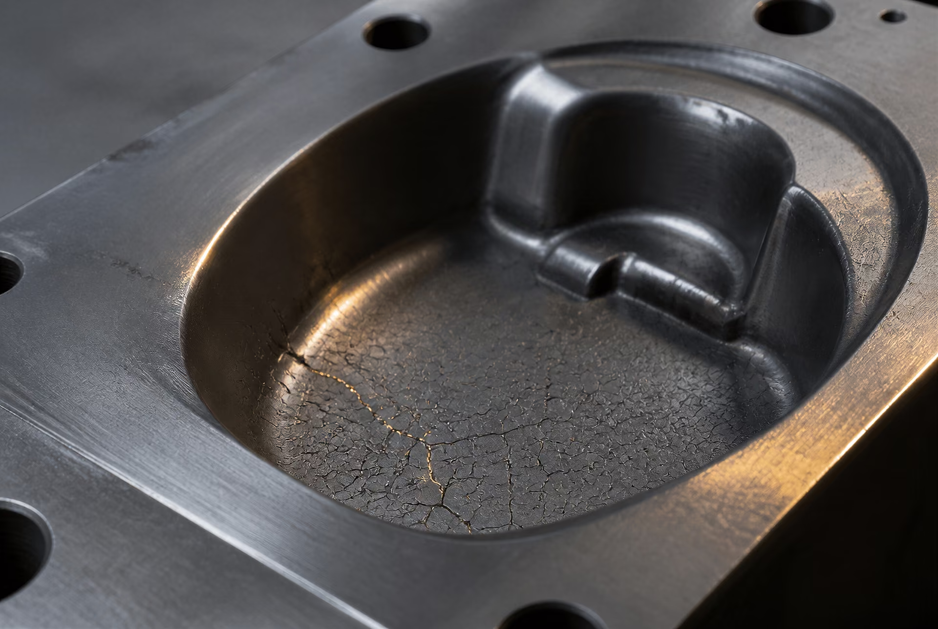
Hot-work tooling often fails through a linked sequence rather than one isolated mechanism. The surface heats rapidly when it contacts the workpiece, cools when sprayed or exposed to air, and then reheats on the next cycle. Repetition creates tensile stresses near the surface. Small cracks form, join, and produce the network known as heat checking or thermal-fatigue cracking. Excessive hardness can reduce the strain the tool tolerates before cracking; insufficient hardness allows plastic deformation, washout, and premature loss of shape.
Tool design and processing matter as much as nominal grade. Large, segregated carbides can act as crack-initiation sites, while coarse prior-austenite grains reduce toughness. Forging practice, cleanliness, and—where applicable—electroslag remelting or powder metallurgy influence the defect population and carbide arrangement. A polished and properly nitrided surface may delay crack initiation, but a surface layer cannot compensate for an unsuitable core or incorrect tempering cycle.
Heat treatment establishes the working balance. Hot-work grades are commonly hardened by austenitizing, air or pressurized-gas quenching, and multiple tempering operations. The aim is not simply maximum room-temperature hardness. The tool must retain sufficient strength after exposure to operating heat while preserving enough toughness to resist impact and thermal strain. A temperature gradient through a large die also makes dimensional control and uniform cooling important.
M and T series for cutting performance
The M series denotes molybdenum high-speed steels, while the T series denotes tungsten high-speed steels. This distinction is chemical and historical, not a simple ranking. M2 is a widely used molybdenum high-speed grade containing substantial tungsten, molybdenum, chromium, and vanadium; its approximate nominal balance is often described as about 6% tungsten, 5% molybdenum, 4% chromium, and 2% vanadium, with carbon near 0.8%. T1, by contrast, is the classic tungsten high-speed grade, commonly associated with roughly 18% tungsten, 4% chromium, and 1% vanadium.
Molybdenum substitutes for part of the tungsten system while maintaining a high population of hard alloy carbides. In M2, molybdenum contributes to secondary hardening and hot hardness without requiring the same tungsten level as T1. The result is a widely applicable cutting-steel family for drills, milling cutters, broaches, taps, reamers, saws, and general-purpose cutting tools. T-series grades remain important where their tungsten-rich carbide system and heat resistance suit the operation, although the choice depends on cutting speed, workpiece material, edge loading, grinding conditions, and tool geometry.
The M family also includes cobalt-containing grades such as M35 and M42. M35 contains approximately 5% cobalt, while M42 contains approximately 8% cobalt. Cobalt raises the temperature at which the hardened structure retains useful strength and can improve cutting performance at high speed, but it does not remove the need for correct heat treatment or provide immunity to chipping. A harder, hotter-running grade may fail sooner if the cutting edge experiences interrupted cuts or insufficient support.
HSS applications show why designation alone is inadequate. A tap requires wear resistance at its flanks and lands, adequate toughness against tooth breakage, and dimensional accuracy through repeated engagement. A reamer needs a stable, keen edge and low dimensional change, since excessive chipping or growth changes the finished hole. A drill, broach, milling cutter, or gear-cutting tool may place different demands on the same steel. Coatings such as titanium nitride or aluminum titanium nitride can reduce friction and limit chemical interaction at the surface, but the substrate still carries the cutting load. Routledge’s Tool Steels: Properties and Performance (2021) treats grade performance through composition, manufacturing process, heat treatment, surface hardening, and coatings for this reason.
Hot hardness, secondary hardening, and red hardness
Room-temperature hardness is only one measurement. A cutting tool can test very hard after quenching and tempering yet lose much of its load-bearing capacity when the cutting edge reaches several hundred degrees Celsius. Hot hardness describes the ability to retain hardness and strength at elevated temperature. Red hardness is the older shop term for the same practical requirement: the edge must remain useful while it visibly heats during cutting.
High-speed steels obtain this behavior from alloy carbides and secondary hardening. During austenitizing, some carbon, tungsten, molybdenum, chromium, and vanadium dissolve into austenite. Quenching produces a hard martensitic structure, usually with retained austenite. During tempering at appropriate temperatures, fine alloy carbides precipitate from the martensite. This precipitation can raise hardness rather than lower it, producing the secondary-hardening peak characteristic of HSS. Repeated tempering also transforms retained austenite and stabilizes dimensions.
The carbide type matters. Vanadium-rich MC carbides are especially hard and resist abrasive wear, while tungsten- and molybdenum-rich carbides support temper resistance and hot hardness. Their size, spacing, orientation, and continuity matter just as much as their presence. A high carbide volume can improve wear resistance but reduce toughness if carbides are coarse, clustered, or aligned along forging flow. Powder-metallurgy HSS can produce a more uniform carbide distribution than conventional ingot metallurgy, yet it still requires a suitable hardening cycle.
Hot-work steels also depend on temper resistance, but their service profile differs from HSS. H13 must tolerate thermal cycling and mechanical contact with hot metal; M2 or M42 must preserve a sharp edge while frictional heat concentrates near the cutting zone. The first may fail through heat checking or gross deformation, the second through flank wear, crater wear, chipping, or plastic rounding of the edge.
A 2020 study reported in MDPI’s Coatings identified heat-treatment parameters as the primary factor controlling tool-core performance. That finding supports a practical rule: composition establishes potential, while heat treatment determines how much of that potential becomes usable. A designation cannot replace controlled austenitizing, quenching, tempering, and inspection.
Selection should therefore follow the failure mode and the production conditions. Uddeholm’s 2024 cold-work guidance expresses the related economic principle as matching the steel to the application and minimizing cost per produced part; for hot-work and high-speed tools, the same idea is better stated as lifecycle performance. The correct grade is the one whose carbide structure, toughness, hot hardness, thermal-fatigue resistance, manufacturing route, and treatment produce the required edge or die life under the actual cycle—not the one carrying the most impressive-sounding letter.
Applications: Matching Grade Family to Failure Mode
A tool-steel grade is not a position on a universal ladder. The letters identify a family, not a guaranteed service result. ASM International defines tool steels as steels used to make tools for cutting, forming, or shaping manufactured parts, while AISI families include W, L, S, O, A, D, H, M, and T series. As explained by Metallurgy at Maricopa Community Colleges (2024), those letters commonly refer to quenching method, principal application, or dominant alloying system.
That distinction matters because a tool can fail by abrasive wear, adhesive galling, plastic deformation, thermal softening, edge chipping, gross fracture, fatigue, or dimensional drift. Carbon, chromium, molybdenum, tungsten, vanadium, and other alloying elements establish hardenability and carbide formation, but manufacturing route controls carbide size, segregation, porosity, and inclusions. Heat treatment then determines the matrix around those carbides. A 2020 MDPI Coatings study identified heat-treatment parameters as the primary factor controlling tool-core performance in the coated system it examined. The coating cannot correct an unsuitable core.
ASTM A681, as listed by ASTM International in 2024, covers the chemical, mechanical, and physical requirements for wrought alloy tool-steel products, including bars, plate, sheet, strip, rod, wire, and forgings normally fabricated into tools, dies, or fixtures. The application decision therefore starts with the service condition, then narrows the family and grade, heat treatment, section size, surface condition, and manufacturing route.
Cutting, drilling, tapping, and reaming
Cutting tools demand a stable sharp edge. The dominant requirements are hardness, hot hardness, wear resistance, and resistance to edge deformation; toughness still matters because interrupted cuts, chatter, inclusions, and poor alignment can chip a very hard edge.
Hand-operated cutting tools often draw from water-hardening W grades, low-alloy L grades, or oil-hardening O grades. AISI W1 can reach high hardness after water quenching, but its shallow hardenability and distortion risk restrict section size and make heat-treatment control important. AISI O1, an oil-hardening grade, offers more predictable hardening through a modest section while retaining useful machinability before treatment. AISI L6, in the low-alloy family, is selected when shock resistance and toughness outweigh maximum abrasion resistance. These are different solutions to different failure modes, not successive quality levels.
Drills, taps, and reamers impose more severe edge and torsional conditions. Taps must resist flank wear and galling while surviving torque reversals and chip evacuation problems. Reamers need edge retention and dimensional stability because they remove little material but must hold a controlled hole size. High-speed steel families—molybdenum high-speed M grades and tungsten high-speed T grades—maintain useful hardness at cutting temperatures that would soften ordinary carbon tool steel. AISI M2 and AISI T1 are familiar reference grades, although the correct choice depends on cutting speed, workpiece hardness, coolant, geometry, and whether the cut is continuous or interrupted.
Carbide structure controls more than nominal hardness. Fine, well-distributed alloy carbides can support wear resistance without creating large crack initiators; coarse or segregated carbides can pull an edge apart during grinding or intermittent cutting. M grades commonly rely on molybdenum and tungsten carbide-forming additions, while T grades carry a stronger tungsten emphasis. The designation alone does not reveal carbide spacing, cleanliness, or the result of forging and powder processing.
Drilling adds torsional fatigue and evacuation stress. A drill with excellent hot hardness may still break if its core is too brittle, its flute finish is poor, or its heat treatment leaves excessive retained austenite. Tapping is especially unforgiving: a small amount of galling can increase torque until the tool fractures. Reaming shifts the balance toward dimensional stability, finish, and controlled wear. Surface treatment can alter friction and adhesion, but it does not replace the required core toughness.
Blanking, punching, heading, and embossing
Blanking and punching are governed by repeated compressive loading, sliding wear, and local stress concentration at the cutting edge. The punch or die must resist plastic indentation and abrasive rounding, yet retain enough chipping resistance to survive misalignment, burrs, slug pulling, and interrupted contact.
AISI D2, in the high-carbon high-chromium family, supplies abundant chromium-rich carbides and high wear resistance. That makes it attractive where edge wear dominates, but its carbide population and heat-treatment response can punish poor grinding practice or severe impact. AISI A2, an air-hardening grade, commonly occupies a different balance: it provides wear resistance with greater toughness and dimensional stability than many higher-carbon, higher-carbide alternatives. AISI O1 can serve less severe cold-work duties where straightforward machining and oil hardening are valuable. AISI S7, a shock-resisting grade, becomes more relevant when chipping or fracture is the main threat rather than maximum sliding-wear life.
Blanking thin sheet and punching thick, abrasive stock are not equivalent operations. Clearance, sheet strength, burr formation, punch slenderness, and press alignment change the stress field. A D-grade punch may resist wear in one line but chip in another if the tool sees impact. Conversely, an S-grade tool may survive shock while losing its edge rapidly under abrasive material. Uddeholm’s 2024 cold-work guidance expresses the practical engineering rule: select a steel that matches the application and minimize cost per produced part. In metallurgical terms, that means comparing sharpening, premature fracture, galling, downtime, and dimensional loss—not simply comparing hardness values.
Cold heading places still another demand on tooling. Heading dies and punches repeatedly absorb impact while compressing wire or bar, so toughness, compressive strength, and fatigue resistance must work together. A die that survives one blow but accumulates microcracks under millions of cycles is not fit for the process. Shock-resisting S grades may suit severe impact, while A, D, or other cold-work families may be used when wear and dimensional retention dominate. The correct heat-treatment condition is a compromise: excessive hardness raises chipping risk; insufficient hardness permits plastic flow and premature enlargement of the die cavity.
Embossing tools often fail through surface damage rather than through a clean fracture. Adhesive pickup, galling, polishing marks, and local plastic deformation can transfer defects into every part. Fine carbide structure, a stable tempered matrix, careful polishing, and controlled surface treatment become central. Dimensional control also depends on heat-treatment distortion, retained austenite, machining allowance, and support of the die during service. A nominally harder steel can produce worse parts if it moves during treatment or damages the sheet surface.
Molding, forming, dies, fixtures, and cutlery
Molding and forming tools expose the steel to contact pressure, sliding, thermal cycling, and sometimes corrosive polymer decomposition products. Cold forming favors dimensional stability, wear resistance, and resistance to galling; hot forming adds thermal fatigue, oxidation, and softening. AISI H13, a chromium hot-work grade, is associated with dies and tooling that operate at elevated temperature because its alloy design supports hot strength and thermal-fatigue resistance. It is not a universal substitute for cold-work grades. AISI D2 or AISI A2 may better address cold abrasive contact, while AISI S7 may be chosen where impact dominates.
Dies are defined by their failure mode as much as by their operation. Drawing dies experience sliding wear and friction. Bending dies see concentrated pressure and edge loading. Extrusion dies face high compressive stress, temperature, and material flow. Molds may require polishability, corrosion resistance, thermal conductivity, or resistance to glass-fiber abrasion. The same family can therefore behave differently after changes in section size, tempering temperature, nitriding, coating, or working surface finish.
Fixtures usually do not need the extreme wear resistance of a blanking die. They need adequate hardness to resist indentation, enough toughness to survive clamping and handling, and dimensional stability across repeated setup cycles. Low-alloy L grades, O grades, or selected A grades can be sensible where machining, moderate wear, and predictable treatment matter more than maximum carbide content. A fixture made excessively hard may become difficult to machine, prone to cracking at sharp corners, and unnecessarily sensitive to impact.
Cutlery illustrates the same balance in a familiar form. A cutting edge needs hardness and wear resistance, but a knife also needs toughness against bending, twisting, and accidental impact. High-carbon tool steels such as AISI D2 can hold an edge through carbide-supported wear resistance, yet their response depends strongly on heat treatment, section thickness, grinding, and edge geometry. Stainless cutlery grades such as AISI 420 are outside the principal AISI tool-steel families, but they show why corrosion resistance can be a service requirement separate from edge retention. A harder edge is not automatically a more durable knife.
The framework described in Tool Steels: Properties and Performance by Routledge (2021) treats composition, manufacturing processes, heat treatment, surface hardening, and coatings as connected controls. NBS Monograph 88 and ASM International provide the historical and metallurgical foundation for that view. Grade selection should follow the dominant damage mechanism, then verify carbide structure, cleanliness, hardening depth, tempering response, distortion, and surface condition. AISI letters narrow the field; they do not make the engineering decision.
Surface Engineering, Coatings, and the Tool Core

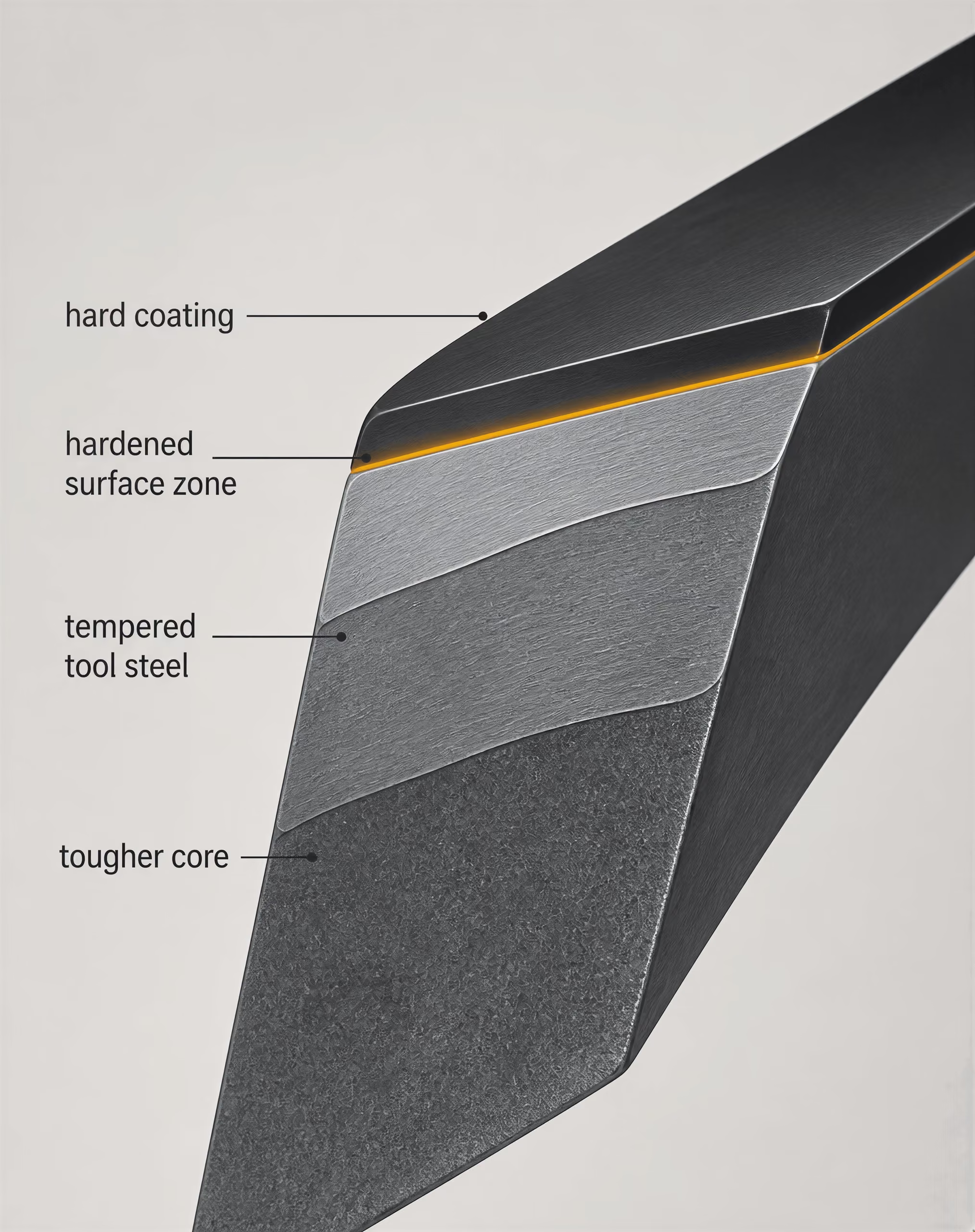
A coated tool is not a coating with a steel handle beneath it. It is a layered mechanical system: the working surface, any diffusion or hardened zone, the coating, the steel substrate, and the heat-treated core must carry load together. ASM International defines tool steels as steels used to make tools for cutting, forming, or shaping manufactured parts, but surface engineering changes how that tool interacts with the workpiece. It does not remove the need to select and heat-treat the underlying grade correctly.
The distinction matters because grade letters do not rank surface performance. An AISI D2 tool steel, an AISI H13 hot-work steel, and an AISI M2 high-speed steel may all receive a hard surface treatment or a deposited coating, yet they have different carbide populations, tempering responses, thermal conductivities, toughness levels, and dimensional changes. Their service limits remain different after coating.
Surface hardening and treated layers
Surface hardening creates a strengthened region in the steel itself. Nitriding introduces nitrogen into the surface, forming alloy nitrides with elements such as chromium, molybdenum, vanadium, or aluminum. Carburizing raises the carbon concentration near the surface before hardening, producing a carbon-rich martensitic case over a lower-carbon core. Induction and laser hardening instead heat a controlled depth rapidly and rely on the existing carbon content to form martensite.
The resulting layer is not equivalent to bulk hardness. A hardened case may be much harder than the interior while retaining a tougher core that supports impact loading. That gradient can reduce plastic indentation and adhesive wear, but it also creates a transition zone where stress concentrates. Case depth, compound-layer thickness, diffusion uniformity, retained austenite, carbide distribution, and tempering condition all affect whether the treatment survives service.
Tool steels are often already selected for high hardness throughout the working section. In those grades, excessive surface hardening can reduce toughness or produce a brittle compound layer rather than a useful load-bearing transition. Decarburization during austenitizing has the opposite problem: the nominal grade may be correct, yet the surface has lost carbon and cannot reach the intended hardness. Grinding away a damaged layer can restore geometry, but it may also expose nonuniform microstructure or reduce the designed case depth.
The 2020 coated-system study published in Coatings identifies heat-treatment parameters as the primary factor controlling tool-core performance. That finding places surface treatment in its proper order. Austenitizing temperature, soaking time, quenching severity, subzero treatment where specified, and tempering determine martensite, retained austenite, carbide condition, and residual stress before a coating is applied. A deposited hard layer cannot turn an under-hardened, over-tempered, decarburized, or crack-sensitive core into a sound tool.
Coatings and substrate support
A coating supplies a thin surface with properties that the bulk steel may not possess at the same time. High hardness can resist abrasive wear and reduce material transfer; chemical stability can limit reaction with the workpiece; a low-friction surface can lower adhesion and heat generation. These are wear and friction benefits, not proof of fracture resistance.
Coating hardness describes resistance to indentation or plastic deformation within the coating. Coating adhesion describes the force required to keep that layer attached to the substrate under thermal, mechanical, and chemical loading. The two properties are separate. A very hard coating with weak adhesion can delaminate in flakes. A well-adhering coating can remain attached while the softer substrate yields beneath it, allowing the surface to crack or deform.
The substrate must therefore provide a sufficiently hard and dimensionally stable foundation. If the core plastically deforms, the coating follows that deformation and may craze, buckle, or detach. If coarse carbides form a discontinuous load path, local stress rises at carbide–matrix interfaces. If the steel contains grinding burns, laps, seams, pores, or tensile surface stresses, a coating may conceal the defect temporarily while leaving the crack-driving condition intact.
Manufacturing route matters as much as nominal composition. Conventional wrought AISI D2 can show directionally distributed chromium-rich carbides, while powder-metallurgy material can provide a finer and more uniform carbide distribution. That difference affects edge support and crack growth beneath a coating. It does not make one route universally superior; the relevant question is whether the microstructure matches the contact pressure, impact level, workpiece abrasiveness, and failure mode.
Deposition temperature must also suit the tempering condition. A tool tempered at a temperature below the coating process temperature may be softened during deposition. For hot-work grades such as AISI H13, repeated thermal cycling can change martensite tempering, precipitate condition, and residual stress even when the coating itself remains intact. Operating temperature adds another variable: a coating that performs well in cool sliding contact may oxidize, soften, react with the workpiece, or lose adhesion in hot forming.
Adhesion, residual stress, and edge integrity
Surface preparation governs the first mechanical connection between coating and steel. It commonly includes degreasing, controlled blasting or polishing, oxide removal, and a final cleaning step, but each operation changes the surface. Roughness can improve mechanical interlocking within limits; excessive roughness creates sharp asperities and thin spots. A polished surface can lower friction but may provide less anchoring and can retain smeared metal from grinding. The preparation must remove contamination without rounding the cutting edge or introducing tensile damage.
Residual stress may help or harm. Compressive stress in a nitrided layer or deposited coating can delay opening of surface cracks. Excessive compressive stress, however, can drive buckling or spallation when the layer is poorly supported. Tensile stress promotes crack initiation, especially at a sharp edge, a grinding burn, a carbide cluster, or a defect in the coating. Thermal-expansion mismatch between coating and steel adds stress during deposition, cooling, and service-temperature changes.
Edge geometry is often the point at which coated tools fail first. A coating has finite thickness and cannot maintain a perfectly uniform layer over an infinitely sharp radius. A feather edge may chip during deposition, handling, or the first contact with the workpiece. A small, controlled edge radius can support the coating and reduce stress concentration, but too large a radius changes cutting geometry and increases forming force. The correct edge is set by the failure mode: abrasive wear, adhesive galling, chipping, plastic collapse, or thermal cracking.
Routledge’s 2021 reference, Tool Steels: Properties and Performance, treats performance through composition, manufacturing processes, heat treatment, surface hardening, and coatings rather than through coating selection alone. That framework agrees with the practical guidance from Uddeholm: cold-work tooling economy depends on matching the tool steel to the application and minimizing cost per produced part. A coating may extend service life when the core, edge, preparation, and thermal cycle are controlled. It cannot compensate for a grade whose toughness is inadequate, a tempering condition that leaves the substrate unstable, or a geometry that concentrates load beyond the coating–substrate system’s capacity.
Standards, Specifications, and Reading a Tool-Steel Datasheet
A tool-steel datasheet contains several different kinds of information that are easy to confuse. A standard defines what a material must satisfy. A grade designation identifies a composition family and a traditional service rationale. A producer’s datasheet then recommends how that grade should be forged, machined, hardened, tempered, and finished. These three layers are related, but they are not interchangeable.
ASM International defines tool steels as “steels used to make tools for cutting, forming, or shaping manufactured parts” (2024). Its AISI classification includes the W, L, S, O, A, D, H, M, and T series (2020). The letters usually describe a quenching method, principal application, or dominant alloying system, not a universal scale of capability. AISI O1, for example, is an oil-hardening cold-work steel; AISI D2 is a high-carbon, high-chromium cold-work steel; and AISI H13 is a chromium hot-work steel. The designation narrows the metallurgical starting point. It does not predict tool life without reference to load, temperature, lubrication, geometry, surface condition, and failure mode.
What ASTM A681 controls
ASTM A681 is a product specification, not a complete statement of how a finished punch, die, cutter, or forming insert will perform. ASTM International states that “ASTM A681 covers the chemical, mechanical, and physical requirements for wrought alloy tool-steel products” (2024). Its scope includes bars, plate, sheet, strip, rod, wire, and forgings normally fabricated into tools, dies, or fixtures. The specification establishes requirements for the supplied steel, including grade chemistry and relevant material properties, while allowing the purchaser and producer to define details such as product form, size, condition, and testing.
The word wrought matters. Wrought products have been mechanically worked by processes such as forging, rolling, or drawing, and their processing history affects grain flow, segregation, porosity, carbide distribution, and directional properties. ASTM A681 therefore belongs to the material-control stage. It does not certify a particular heat-treatment cycle for every tool geometry, nor does it remove the need to inspect the finished part.
A datasheet may list AISI D2, ASTM A681, and a proprietary internal designation on the same page. Those entries do different jobs. “AISI D2” identifies the recognized grade family. “ASTM A681” identifies a specification against which the wrought product may be supplied. The producer’s internal designation may describe a melting route, remelting route, cleanliness level, or processing condition. It should not be read as a new universal grade unless the document defines its chemistry and requirements.
The standard also should not be treated as a ranking system. The AISI W, L, S, O, A, D, H, M, and T families address different compromises. W grades depend chiefly on water quenching and can provide high hardness in suitable sections, while S grades emphasize shock resistance. M and T grades are high-speed families based mainly on molybdenum and tungsten alloying, respectively. A D-grade composition can support substantial carbide-related wear resistance, but its fracture behavior may be unsuitable where repeated impact dominates. The correct comparison is between the required failure resistance and the material’s carbide structure, toughness, hardenability, hot hardness, dimensional stability, and attainable surface condition.
Chemical composition versus delivered condition
The chemistry table normally gives nominal composition ranges, not a complete description of the steel’s working state. Carbon affects matrix hardness and carbide formation. Chromium, molybdenum, tungsten, and vanadium influence hardenability, secondary hardening, hot hardness, and the type and volume of alloy carbides. Silicon and manganese affect deoxidation and hardenability, while sulfur may be controlled for machinability at the cost of possible effects on transverse toughness. The same nominal chemistry can produce different behavior when carbide size, segregation, inclusion content, and prior-austenite grain size differ.
The delivered condition is therefore a separate line of inquiry. “Annealed” generally means that the steel was supplied after a controlled softening treatment intended to reduce hardness and improve machinability. It does not mean that the steel has its final tool properties. An annealed D2 bar and a vacuum-hardened D2 punch are the same grade, but not the same material condition in service. The datasheet may also specify maximum annealed hardness, spheroidized carbide structure, grain size, or a microstructural requirement. These details matter because coarse carbides and banding can promote chipping, while excessive grain growth reduces toughness.
Ask whether the listed properties are longitudinal or transverse. Rolling and forging can elongate inclusions and carbide stringers, producing directional differences in ductility, impact resistance, and fracture path. A longitudinal tensile result cannot automatically represent a transverse punch edge. Cleanliness ratings and inclusion inspections provide additional information, but they do not describe every defect population. Manufacturing route—conventional ingot metallurgy, electroslag remelting, or another refined process—can alter segregation and inclusion morphology even when the grade name remains unchanged.
Routledge’s Tool Steels: Properties and Performance (2021) treats grade behavior through composition, manufacturing processes, heat treatment, surface hardening, and coatings. That ordering is useful: composition establishes potential, manufacturing determines part of the defect and carbide population, and heat treatment determines the matrix and final balance of hardness and toughness. A 2020 study in MDPI’s Coatings identified heat-treatment parameters as the primary factor controlling tool-core performance in the coated system examined. The result does not make chemistry unimportant; it shows why a chemistry-only comparison is incomplete.
Hardness ranges, test methods, and heat-treatment notes
Hardness on a datasheet may describe the annealed delivery condition, a recommended hardened condition, or a target after tempering. Read the heading and footnotes before comparing values. A stated range such as “maximum annealed hardness” is a machinability specification, not evidence of the hardness available after hardening. A recommended austenitizing temperature, quench medium, tempering temperature, and holding time is a processing route, not a guarantee for every section size.
| Test method | Indenter or measurement basis | Typical use described |
|---|---|---|
| Rockwell C | Diamond cone with specified loads | Bulk hardness of hard tool steels |
| Brinell | Indenter ball | Softer or larger-scale material |
| Vickers | Diamond pyramid | Small regions, case depths, or microstructural areas |
Rockwell, Brinell, and Vickers values are not interchangeable numbers. Rockwell C, commonly written HRC, uses a diamond cone and a specified minor and major load; ASTM E18 governs Rockwell hardness testing. Brinell, covered by ASTM E10, uses an indenter ball and is more suited to softer or larger-scale material. Vickers, covered by ASTM E384 for microindentation and related hardness testing, uses a diamond pyramid and can measure small regions, case depths, or individual microstructural areas. Different loads, indenter geometries, surface finishes, and specimen thicknesses can change the result.
Conversion tables provide approximate equivalents within defined ranges. They do not turn one test into another measurement with identical uncertainty, especially across very hard tool steels, thin sections, decarburized surfaces, or heterogeneous carbide structures. A polished Vickers traverse through a hardened case answers a different question from an HRC reading taken on a bulk specimen.
Finally, inspect the heat-treatment notes for grain-size control, preheating, austenitizing, quenching, cryogenic treatment, tempering, and distortion limits. NBS Monograph 88 remains a useful federal reference for historical terminology and foundational steel metallurgy, while ASTM supplies the product framework. Neither replaces a process qualification on the actual tool. Uddeholm’s cold-work guidance expresses the practical objective clearly: select a steel that matches the application and minimize cost per produced part (2024). In engineering terms, that means minimizing lifecycle loss from wear, chipping, plastic deformation, heat checking, corrosion, and dimensional change—not selecting the highest hardness number on a datasheet.
Failure Analysis: Diagnosing Why a Tool Failed
A failed tool should not be diagnosed from its grade designation alone. AISI W, L, S, O, A, D, H, M, and T families describe quenching method, principal application, or dominant alloying system; they do not form a universal ranking from weak to strong. An AISI D2 punch, an AISI S7 chisel, and an AISI H13 die may all be correctly selected for different service conditions, yet each can fail if its heat treatment, edge geometry, surface finish, or loading cycle is wrong.
Failure-analysis sequence
- Record service conditions Document temperature, load, stroke rate, workpiece, lubricant, part count, and the first damage location.
- Preserve the fracture Do not polish, blast, or handle the fracture face before examination.
- Compare specimens Compare the failed tool with an unused tool and, where possible, a tool that completed its expected service.
- Test the structure Combine visual inspection, fractography, hardness mapping, metallography, and dimensional measurement.

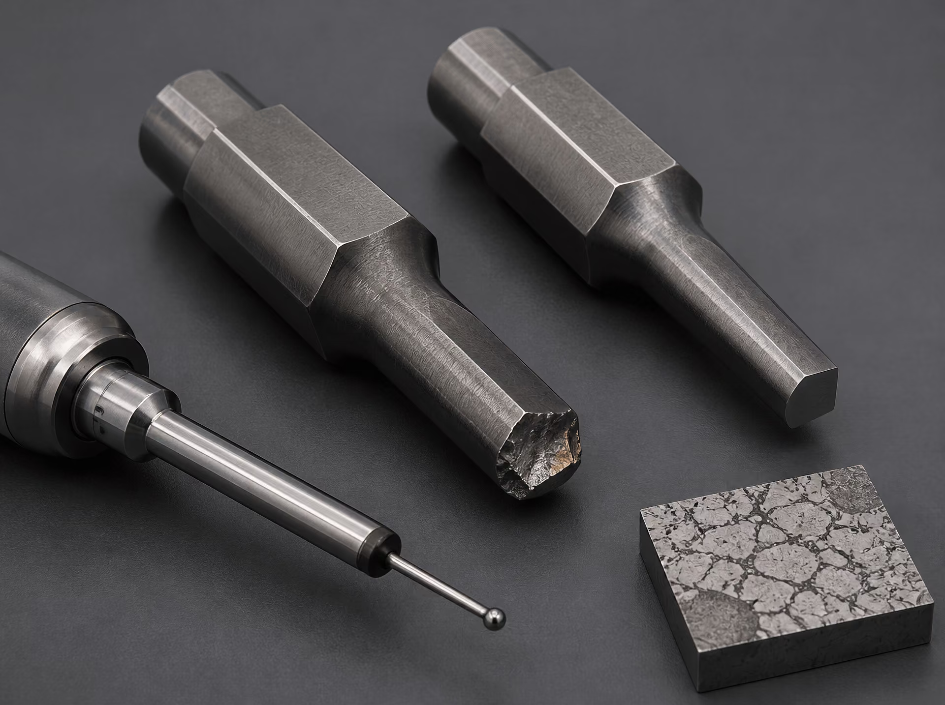
The first task is to preserve evidence. Record the tool location, operating temperature, load, stroke rate, workpiece material, lubricant, number of parts produced, and the exact position of the first visible damage. Compare a failed tool with an unused tool and, when possible, with a tool that completed its expected service. The fracture face should not be polished, blasted, or handled before examination. A failure investigation then combines visual inspection, fractography, hardness mapping, metallography, dimensional measurement, and review of the heat-treatment record.
This approach turns classification into engineering reasoning. ASM International defines tool steels as steels used to make tools for cutting, forming, or shaping manufactured parts, while ASTM A681 covers the chemical, mechanical, and physical requirements for wrought alloy tool-steel products, including bars, plate, sheet, strip, rod, wire, and forgings. Neither reference promises that a nominal grade will perform correctly under every load. Composition establishes potential; manufacturing route establishes segregation, inclusions, and carbide distribution; heat treatment determines much of the final structure.
Plastic deformation and premature wear
Plastic deformation usually means that the local stress exceeded the tool’s yield or compressive strength at its service temperature. In a cold punch, the nose may mushroom, upset, or sink. In a hot-work die, the cavity may widen or lose detail after repeated contact with heated stock. The central question is whether the tool lacked sufficient hardness and compressive strength at the actual working temperature, rather than whether its room-temperature hardness looked acceptable.
Hot-work grades such as AISI H13 depend on retained hot hardness, temper resistance, and thermal-fatigue resistance. A cold-work grade can show high room-temperature hardness yet soften during an unexpectedly hot forming operation. Tempering at too low a temperature, excessive austenitizing temperature, decarburization, or an incorrect cooling schedule can leave the core unable to support the applied stress. A review of furnace charts, quench records, tempering times, and measured hardness is therefore essential. The 2020 MDPI Coatings study identified heat-treatment parameters as the primary factor controlling tool-core performance; that finding makes a heat-treatment record more informative than a grade label by itself.
Hardness mapping separates a core problem from a surface problem. Measure the failed region, an unaffected region, and a cross-section from the working edge toward the center. A steep hardness loss near the surface may indicate decarburization, overheating, grinding burn, or inadequate case treatment. Uniformly low hardness points toward incorrect austenitizing, quenching, or tempering. High hardness with deformation suggests insufficient compressive strength for the load, excessive section stress, or a service temperature beyond the grade’s temper-resistance range.
Premature wear requires a different question: what removed material? Abrasive wear produces aligned scratches, rounded edges, and loss of profile where hard particles or asperities slide across the tool. Adhesive wear produces transferred workpiece material, torn patches, and localized welding. Carbide population matters in both cases. Carbon and carbide-forming elements such as chromium, molybdenum, tungsten, and vanadium can raise wear resistance, but large, uneven carbides may reduce edge support and promote fracture. AISI D2, for example, contains a high chromium-carbide population that can resist abrasion, while its performance depends strongly on carbide size, orientation, heat treatment, and edge design.
Metallography should examine carbide type, size, banding, retained austenite, decarburization, and nonmetallic inclusions. A polished and etched section from the worn zone can show whether the tool has a fine, reasonably uniform structure or a coarse carbide network that concentrates stress. The 2020 ASM International treatment of tool steels correctly links performance to combinations of wear resistance, toughness, hot hardness, carbides, and heat treatment. Raising hardness alone cannot repair an unsuitable carbide structure or a mismatched service condition.
Chipping, cracking, and fracture
Chipping is the loss of small fragments from an edge, corner, punch nose, or die land. It commonly reflects excessive brittleness, an edge that is too thin or sharp for the load, poor support behind the edge, or coarse carbides intersecting the working surface. A tool can chip even when its measured hardness is within specification. Excessive retained austenite, untempered martensite, carbide segregation, grinding damage, and a poor transition radius can all reduce local tolerance to impact.
Fractography gives the failure sequence. A brittle fracture face may contain bright cleavage facets, river patterns, and little plastic deformation. Ductile overload tends to show dimples, while fatigue produces a crack-origin region followed by progressive markings and a final overload zone. The origin should be traced back to a corner, machining mark, inclusion, carbide cluster, or grinding groove. A fracture that begins at the surface and runs inward demands a different response from one that begins at an internal inclusion or a banded carbide region.
Cracking may arise during quenching, after grinding, or during service. Quench cracks often follow sharp corners, abrupt section changes, holes, or areas of uneven cooling. They can be associated with excessive thermal gradients, high transformation stress, or austenitizing conditions that produced an overly coarse austenite grain. The heat-treatment record should be checked for furnace temperature, soak time, protective atmosphere, quench medium, agitation, transfer delay, and tempering immediately after quenching.
Grinding cracks are shallow, tight, and often parallel to the grinding direction. Magnetic-particle inspection can reveal them, while metallography may show a retempered or overtempered layer and tensile residual stress beneath the surface. Excessive wheel pressure, a dull wheel, inadequate coolant, or too much stock removal per pass can create damage that remains invisible until the tool is loaded. Fatigue cracks usually begin at such a stress raiser and extend with repeated cycles, even when each individual load is below the one-time fracture strength.
Heat checking, galling, and dimensional failure
Heat checking is a network of fine cracks caused by repeated heating and cooling of the working surface. It is common in hot-work dies, where the surface expands during contact with hot stock and contracts during cooling. Thermal cycling, steep temperature gradients, inadequate preheating, poor cooling control, and a rough or damaged surface increase the driving force. Crack networks should be mapped against die temperature, spray pattern, cooling-channel position, and contact areas. Metallography can establish whether the cracks are confined to the surface or have linked with deeper defects.
Surface condition often decides how quickly heat checking develops. Grinding marks, EDM recast layers, decarburized regions, coating defects, and sharp machining transitions act as crack starters. A smooth surface is not automatically safe: grinding burn can leave a tensile-stressed, softened layer beneath a visually acceptable finish. Hardness traverses, etching, and residual-stress-sensitive inspection help separate thermal fatigue from ordinary abrasion.
Galling is adhesive damage. Local welding between tool and workpiece transfers material, tears the surface, and may raise ridges that then accelerate wear or cause sudden scoring. The investigation should examine lubricant breakdown, contact pressure, sliding distance, surface roughness, workpiece cleanliness, and tool hardness. A chemically compatible surface treatment or coating may help, but it cannot compensate for poor alignment, inadequate clearance, or a softened substrate.
Dimensional failure includes loss of die clearance, punch shortening, cavity growth, warpage, and unacceptable change during heat treatment. Measure the failed tool against its drawing and inspect symmetry across the section. Distortion can result from retained austenite transforming during service, uneven machining before hardening, nonuniform quenching, carbide segregation, or inadequate stress relief. The Routledge volume Tool Steels: Properties and Performance (2021) treats composition, manufacturing process, heat treatment, surface hardening, and coatings as connected variables for this reason.
The useful conclusion is not that one AISI family should replace another. Uddeholm’s cold-work guidance frames selection around matching the steel to the application and minimizing cost per produced part; technically, that means controlling lifecycle failure rather than chasing a grade label. The correct diagnosis identifies the failure mechanism, verifies it with physical evidence, and then changes the relevant variable: steel structure, geometry, heat treatment, surface condition, process temperature, lubrication, or loading.
A Practical Selection Method Without a Universal 'Best' Grade
A tool-steel grade should be selected from the service problem backward, not from a letter designation forward. ASM International defines tool steels as “steels used to make tools for cutting, forming, or shaping manufactured parts” (2024). That definition describes a function, not a ranking. AISI families W, L, S, O, A, D, H, M, and T group steels by features such as quenching method, principal application, or dominant alloying system. The letter does not predict service life by itself.
ASTM A681 provides the standards framework for wrought alloy tool-steel products, including bars, plate, sheet, strip, rod, wire, and forgings normally fabricated into tools, dies, or fixtures. Its scope covers chemical, mechanical, and physical requirements, but a conforming analysis is only the starting point. Carbide size and distribution, segregation, cleanliness, forging or rolling history, heat treatment, section size, grinding damage, and surface condition can change the result at the tool face.
Define load, temperature, and contact conditions
Begin by describing the workpiece and the actual contact. “Cold forming” is not enough. Record whether the workpiece is low-carbon steel, stainless steel, aluminum alloy, copper alloy, nickel alloy, powder compact, glass-filled polymer, or another material; its hardness, strength, ductility, scale, coatings, and any abrasive inclusions may matter more than its nominal product name.
Then identify the mechanical load. A punch experiencing a short, high-energy impact has a different problem from a die receiving a steady compressive load. Note contact pressure, loading frequency, stroke speed, alignment, unsupported length, and stress concentration at radii, holes, corners, and inserts. A tool can possess high compressive strength yet fail when a notch, misalignment, or thin section converts the load into bending or tensile stress.
Contact movement also needs a precise description. Is the dominant action cutting, indentation, extrusion, sliding, rolling, or repeated impact? Sliding against a clean polymer may produce a different wear mechanism from sliding against scale or carbide particles. Abrasive wear may favor a hard carbide population, while adhesive wear may be controlled by surface chemistry, finish, lubrication, and workpiece transfer. Large primary carbides can improve resistance to some abrasive mechanisms but may also provide crack-initiation sites when the tool is shocked or bent.
Temperature must include both average and peak values. Hot-work tooling sees thermal cycling, oxidation, heat checking, and loss of hardness, while a nominally cold-work tool can heat locally at a cutting edge or high-speed sliding contact. Record heating and cooling rates, dwell time, coolant chemistry, and the number of cycles per shift. Production cycle matters because a tool that survives a short trial may fail after thousands of thermal or impact repetitions.
Finally, define dimensional limits. Allowable distortion may determine whether an oil-hardening grade is practical for a slender punch or whether an air-hardening route needs special fixturing and machining allowances. Surface finish, edge sharpness, polishing direction, and grinding practice belong in the specification, not as afterthoughts. Maintenance constraints complete the picture: can the tool be removed for stress relieving, recoated, reground, or selectively replaced, and how much downtime is acceptable?
Rank failure modes and tolerable risk
Selection checklist
- Workpiece Record material, hardness, strength, ductility, scale, coatings, and abrasive inclusions.
- Mechanical load Record pressure, impact, frequency, alignment, unsupported length, and stress concentrations.
- Contact movement Classify the operation as cutting, indentation, extrusion, sliding, rolling, or repeated impact.
- Temperature Record average and peak temperatures, heating and cooling rates, dwell time, and coolant.
- Dimensional limits Specify allowable distortion, surface finish, edge geometry, and maintenance constraints.
List the likely failure modes before naming a grade. Typical categories include gross breakage, chipping, plastic deformation, abrasive wear, adhesive wear, galling, thermal softening, heat checking, corrosion, distortion, and loss of edge geometry. Rank them by production consequence and probability. A chipped punch may contaminate parts and stop a line immediately; gradual flank wear may be acceptable if inspection catches it before dimensional drift.
This ranking prevents a common mistake: maximizing hardness or carbide content when toughness controls the real loss. Shock-resisting S-series steels may be justified where impact and edge chipping dominate. D-series high-carbon, high-chromium steels may suit severe cold-work wear, but their carbide structure and toughness must be considered at the same time. O-series oil-hardening steels can offer a useful balance for some dies and fixtures, while A-series air-hardening steels may reduce quench distortion in suitable sections. W-series water-hardening steels, L-series low-alloy steels, and H-series hot-work steels occupy different service spaces; none is a general performance ladder.
For cutting at elevated speed, M-series molybdenum high-speed steels and T-series tungsten high-speed steels are assessed through hot hardness, edge retention, toughness, and grinding response, not by the alphabet alone. S, H, D, and high-speed grades may all appear in tooling, yet the decisive variable remains the failure mechanism under the stated contact and temperature.
Separate tolerable damage from unacceptable damage. If a tool may wear to a measurable limit, specify that limit and the inspection interval. If any crack is unacceptable, favor a design and material route with greater fracture tolerance, even if that sacrifices some wear resistance. Risk also includes hidden damage: subsurface grinding cracks, decarburized edges, retained austenite, coarse carbides, and heat-treatment distortion can remain invisible until service.
Validate through heat treatment and service evidence
After narrowing the grade family, verify the complete thermal route. Austenitizing temperature, preheating, holding time, quench medium, pressure, tempering temperature, number of tempers, cryogenic treatment where justified, and stress relief should be tied to the actual section size and furnace capability. The same nominal grade can produce different hardness, retained-austenite content, toughness, and dimensional change when the cross-section or quench severity changes.
Heat treatment deserves priority. A 2020 study in Coatings identified heat-treatment parameters as the primary factor controlling tool-core performance in the examined coated system. Composition and manufacturing route establish potential and defect population; treatment determines how much of that potential becomes usable structure. Measure hardness across the section when appropriate, inspect decarburization, check dimensions before and after treatment, and examine carbides or fracture surfaces when failure risk warrants it.
Surface engineering must be checked against the core. Polishing, honing, nitriding, plating, and physical or chemical vapor deposition can alter friction, adhesion, and wear, but coatings do not repair a weak substrate or an unsuitable carbide structure. Confirm substrate hardness, tempering resistance, coating temperature, edge radius, surface roughness, adhesion, and any post-coating grinding. Routledge’s 2021 Tool Steels: Properties and Performance treats performance through composition, manufacturing processes, heat treatment, surface hardening, and coatings for this reason.
Use service evidence rather than a catalog claim. Compare documented tool life, failure photographs, inspection records, part dimensions, and maintenance intervals from a tool with the same workpiece, contact, cycle, and geometry. NBS Monograph 88 remains useful for historical terminology and foundational steel metallurgy; ASTM, AISI, ASM International, MDPI, and Uddeholm provide complementary standards, classification, research, and application guidance.
Tooling economics should be evaluated by lifecycle cost per produced part rather than purchase price or maximum hardness. Strong evidence
The economic test is cost per produced part across service life. Include machining, heat treatment, coating, sharpening, replacement, rejected parts, downtime, and safe failure limits. Uddeholm’s 2024 cold-work guidance states that tooling economy depends on matching steel to the application with the objective of minimizing cost per produced part. That principle is an engineering comparison, not a claim about purchase price, stock, or supplier performance.
Historical and Technical Reference Framework
AISI classification as technical shorthand
Tool-steel nomenclature is useful because it compresses a large amount of metallurgical information into a short designation, but the letter is not a universal ranking. The AISI system organizes the principal families as W, L, S, O, A, D, H, M, and T. ASM International describes tool steels as steels used to make tools for cutting, forming, or shaping manufactured parts; the designation system helps identify the general material class behind that function.
| Letter | Meaning | Representative application space |
|---|---|---|
| W | Water-hardening | Small hand tools and simple punches |
| L | Low-alloy | Toughness-oriented tooling and fixtures |
| S | Shock-resisting | Repeated impact and interrupted loading |
| O | Oil-hardening | Small cold-work dies and cutting tools |
| A | Air-hardening | Cold-work dies requiring reduced quench shock |
| D | High-carbon, high-chromium | Wear-dominated cold-work tooling |
| H | Hot-work | Elevated-temperature dies and tooling |
| M | Molybdenum high-speed | High-speed cutting tools |
| T | Tungsten high-speed | Heat-resistant cutting tools |
The letters usually point to a quenching method, a principal application, or a dominant alloying system. W grades are water-hardening steels. L grades are low-alloy tool steels, while S grades are shock-resisting steels. O designates oil-hardening cold-work steels; A indicates air-hardening grades; and D identifies high-carbon, high-chromium cold-work steels. H covers hot-work steels. M and T identify molybdenum high-speed and tungsten high-speed steels, respectively.
That shorthand does not tell the whole engineering story. AISI O1 and AISI D2 are both associated with cold-work tooling, yet their carbon, chromium, and carbide populations produce different responses to hardening, tempering, wear, chipping, and dimensional change. AISI S7 may tolerate impact that would fracture a more wear-oriented grade, while a high-speed steel may retain cutting hardness at temperatures that would soften a simpler carbon tool steel. None of those observations makes one family universally superior.
Composition establishes potential, not finished behavior. Carbon supplies martensitic hardness and combines with alloying elements to form carbides. Chromium, molybdenum, tungsten, and vanadium affect hardenability, secondary hardening, hot hardness, and wear resistance; nickel and manganese influence hardenability and toughness in selected compositions. The amount, type, size, spacing, and distribution of carbides matter just as much as a nominal chemical range. Large or poorly distributed carbides can assist abrasive wear resistance while increasing crack sensitivity and reducing edge toughness.
Manufacturing route adds another variable. Conventional wrought processing, electroslag remelting, powder metallurgy, forging practice, and annealing history can produce different carbide structures and defect populations under the same broad grade designation. A designation therefore identifies a composition family and expected processing envelope. It does not replace a microstructural examination or a heat-treatment record.
ASTM A681 supplies the standards framework for wrought alloy tool-steel products. ASTM International states in its 2024 description that ASTM A681 covers the chemical, mechanical, and physical requirements for wrought alloy tool-steel products, including bars, plate, sheet, strip, rod, wire, and forgings normally fabricated into tools, dies, or fixtures. Its language is specification language: it defines requirements and acceptance boundaries. It is not a service-life prediction and does not rank AISI families by output, toughness, or tool life.
NBS Monograph 88 and federal metallurgy references
NBS Monograph 88 belongs to the federal technical literature that helped establish consistent terminology for tool steels and steel metallurgy. The National Bureau of Standards, now the National Institute of Standards and Technology, produced references of this type to connect composition, phase changes, heat treatment, and measured properties in a form usable by laboratories, designers, and manufacturing organizations. Its value today is historical and technical rather than promotional.
A reference such as NBS Monograph 88 is particularly useful when a modern designation is being read against older literature. Terms such as hardenability, critical temperature, spheroidized annealing, retained austenite, secondary hardening, temper brittleness, and decarburization have specific metallurgical meanings. They should not be treated as interchangeable descriptions of hardness. Hardenability, for example, concerns the depth and distribution of martensitic transformation under a given cooling condition; it is not the same property as maximum attainable hardness.
The federal reference also provides a foundation for understanding why heat treatment changes the same nominal grade in different ways. Austenitizing temperature controls dissolution of carbides and the carbon and alloy content available to austenite. Cooling rate controls transformation products and retained austenite. Tempering changes martensite, relieves stress, and may produce secondary hardening in alloy systems containing molybdenum, tungsten, vanadium, or chromium. Excessive temperature, insufficient soaking, decarburization, quench cracking, and distortion can all move a tool away from the expected property range.
Historical references must still be read critically. Furnace control, cleanliness, remelting practice, powder processing, vacuum heat treatment, and surface engineering have changed. A historical description of a grade may therefore remain correct in principle while failing to describe the carbide scale, inclusion population, or coating interface of a current product made under a different route.
ASM, ASTM, and modern property literature
ASM International serves several different purposes in the reference chain. An ASM Handbook entry typically organizes accepted engineering knowledge around composition, processing, microstructure, properties, testing, and applications. An ASM monograph may develop a narrower subject in greater depth, often linking mechanisms across several grades or processing routes. Neither format should be confused with ASTM A681. ASM explains and interprets; ASTM specifies.
Educational metallurgy summaries, such as the 2024 tool-steel material from Maricopa Community Colleges, are useful for learning the logic of the AISI letters. They correctly identify the letters as indicators of quenching method, principal application, or dominant alloying system. Their compact format, however, cannot replace the composition limits, product requirements, heat-treatment recommendations, or supplementary requirements in the current ASTM standard and producer data.
Modern property literature adds another layer. The 2020 study published in MDPI’s Coatings identified heat-treatment parameters as the primary factor controlling tool-core performance in the coated system it examined. That finding matters because a coating cannot repair an incorrectly hardened core, excessive retained austenite, a coarse carbide network, or a crack-sensitive heat-treatment condition. Coating adhesion, substrate hardness, surface preparation, residual stress, and operating temperature must be considered together.
Routledge’s 2021 Tool Steels: Properties and Performance treats grade behavior through composition, manufacturing processes, heat treatment, surface hardening, and coatings. This reflects the correct engineering sequence. Uddeholm’s 2024 cold-work guidance makes the related service point that tool-steel selection should match the application and minimize cost per produced part; expressed technically, the relevant measure is lifecycle performance under the actual failure mode.
Readers should therefore cross-check every designation against the current edition of ASTM A681 or another applicable standard, the heat-treatment guidance for that exact grade, the expected carbide and matrix structure, and the intended service. A punch, tap, reamer, embossing tool, cutlery edge, forming die, or hot-work insert may fail by abrasive wear, adhesive wear, plastic deformation, thermal fatigue, chipping, or gross fracture. The grade letter narrows the starting field. Composition, manufacturing route, heat treatment, surface condition, and failure analysis determine whether the selected steel is suitable for the work.
References
- [1] The effect of heat treatment on tool-core performance in a coated system. Coatings, 2020. https://www.mdpi.com/2079-6412/10/3/265